OVFKWC-K24-2J0Single Band Single Mode Cellular Phone
Kyocera International, Inc
Click to zoom
Application Details
- Equipment Class
- PCE - PCS Licensed Transmitter held to ear
- Date of Grant
- Aug 16, 2006
- Application Purpose
- Original Equipment
- Date of Application
- Aug 16, 2006
- Equipment Note
- Single Band Single Mode Cellular Phone
- Frequency Range
- 1851.25000000 - 1908.75000000
- Company
- Kyocera International, Inc
- Country
- United States
Documents & Files
Document Text
Text extracted from the exhibit documents filed with the FCC. Open a document above to read the original.
Users Manual
5 ii User Guide for the K325 Phone This manual is based on the production version of the Kyocera K325 phone. Software changes may have occurred after this printing. Kyocera reserves the right to make changes in technical and product specifications without prior notice. The products and equipment described in this documentation are manufactured under license from QUALCOMM Incorporated under one or more of the following U.S. patents: 4,901,307 5,056,109 5,101,501 5,109,390 5,228,054 5,267,261 5,267,262 5,337,338 5,414,796 5,416,797 5,490,165 5,504,773 5,506,865 5,511,073 5,535,239 5,544,196 5,568,483 5,600,754 5,657,420 5,659,569 5,710,784 5,778,338 The Kyocera Wireless Corp. (“KWC”) products described in this manual may include copyrighted KWC and third party software stored in semiconductor memories or other media. Laws in the United States and other countries preserve for KWC and third party software providers certain exclusive rights for copyrighted software, such as the exclusive rights to distribute or reproduce the copyrighted software. Accordingly, any copyrighted software contained in the KWC products may not be modified, reverse engineered, distributed or reproduced in any manner not permitted by law. Furthermore, the purchase of the KWC products shall not be deemed to grant either directly or by implication, estoppel, or otherwise, any license under the copyrights, patents or patent applications of KWC or any third party software provider, except for the normal, non-exclusive royalty-free license to use that arises by operation of law in the sale of a product. Kyocera is a registered trademark and Strobe is a trademark of Kyocera Corporation. QUALCOMM is a registered trademark of QUALCOMM Incorporated. Openwave is a trademark of Openwave Systems Incorporated. eZiText is a registered trademark of Zi Corporation. TransFlash is a trademark of SanDisk Corporation. All other trademarks are the property of their respective owners. Carrier, the Carrier signature, and the Carrier trademark and logo are registered trademarks of Carrier Enterprises Ltd. AOL is a registered trademark of America Online, Inc. AIM is a registered trademark of America Online, Inc. Copyright © 2006 Kyocera Wireless Corp. All rights reserved. Ringer Tones Copyright © 2000-2002 Kyocera Wireless Corp. 82-G1631-1EN, Rev. X1 FCC Notice This device complies with part 15 of the FCC rules. Operation is subject to the following two conditions: (1) This device may not cause harmful interference, and (2) this device must accept any interference received, including interference that may cause undesired operation. To maintain compliance with FCC RF exposure guidelines, if you wear a handset on your body, use Kyocera Wireless Corp. (KWC) supplied and approved accessories. Other accessories used with this device for body- worn operations must not contain any metallic components and must provide at least 15 mm separation distance including the antenna and the user’s body. THIS MODEL PHONE MEETS THE GOVERNMENT’S REQUIREMENTS FOR EXPOSURE TO RADIO WAVES. Your wireless phone is a radio transmitter and receiver. It is designed and manufactured not to exceed the emission limits for exposure to radio frequency (RF) energy set by the Federal Communications Commission of the U.S. Government. These limits are part of comprehensive guidelines and establish permitted levels of RF energy for the general population. User Guide for the K325 phoneiii The guidelines are based on standards that were developed by independent scientific organizations through periodic and thorough evaluation of scientific studies. The standards include a substantial safety margin designed to assure the safety of all persons, regardless of age and health. The exposure standard for wireless mobile phones employs a unit of measurement known as the Specific Absorption Rate, or SAR. The SAR limit set by the FCC is 1.6 W/kg.* Tests for SAR are conducted using standard operating positions specified by the FCC with the phone transmitting at its highest certified power level in all tested frequency bands. Although the SAR is determined at the highest certified power level, the actual SAR level of the phone while operating can be well below the maximum value. This is because the phone is designed to operate at multiple power levels so as to use only the power required to reach the network. In general, the closer you are to a wireless base station antenna, the lower the power output. Before a phone model is available for sale to the public, it must be tested and certified to the FCC that it does not exceed the limit established by the government-adopted requirement for safe exposure. The tests are performed in positions and locations (e.g., at the ear and worn on the body) as required by the FCC for each model. Body-worn measurements differ among phone models, depending upon availability of accessories and FCC requirements. While there may be differences between the SAR levels of various phones and at various positions, they all meet the government requirement for safe exposure. The FCC has granted an Equipment Authorization for this model phone with all reported SAR levels evaluated as in compliance with the FCC RF emission guidelines. SAR information on this model phone is on file with the FCC and can be found under the Display Grant section http://www.fcc.gov/oet/fccid after searching on the FCC ID: OVFKWC-K24-2J0. Additional information on SAR can be found on the Cellular Telecommunications and Internet Association (CTIA) web-site at http://www.wow-com.com. * In the United States and Canada, the SAR limit for mobile phones used by the public is 1.6 watts/ kg (W/kg) averaged over one gram of tissue. The standard incorporates a substantial margin of safety to give additional protection for the public and to account for any variations in measurements. Caution The user is cautioned that changes or modifications not expressly approved by the party responsible for compliance …
Text truncated - open the document above for the full version.
Cover Letter(s)
FCC ID: OVFKWC-K24-2J0 July 26, 2006 Federal Communications Commission Authorization and Evaluation Division 7435 Oakland Mills Road Columbia, Maryland 21046 Re: Application for PCS Transceiver Certification To Whom It May Concern: Kyocera Wireless Corporation (KWC) herein submits the Application for Equipment Authorization (FCC Form 731) and Exhibits for Certification of a PCS Transceiver, FCC ID: OVFKWC-K24-2J0. Applicant: Kyocera Wireless Corp. 10300 Campus Point Drive San Diego, CA 92121 Manufacture: Kyocera Wireless Corp. 10300 Campus Point Drive San Diego, CA 92121 The equipment is for mobile station PCS system use. The OVFKWC-K24-2J0 is in full compliance with all parts of ANSI J-STD-08, Recommended Minimum Performance Requirements for 1.8 to 2 GHz Code Division Multiple Access (CDMA) Personal Stations, issue July 1996. Information concerning how the ESN protection requirements are met is provided in Exhibit 10. Please contact me at Tel: (858) 882-3585 or Email: [email protected] if there are any questions or if any additional information is needed. Kyocera Wireless Corp. Thuy To Regulatory Engineer Kyocera Wireless Corp. 1
Cover Letter(s)
FCC ID: OVFKWC-K24-2J0 July 26, 2006 Federal Communications Commission Authorization and Evaluation Division 7435 Oakland Mills Road Columbia, Maryland 21046 Re: Request of Confidentiality for FCC ID: OVFKWC-K24-2J0 To Whom It May Concern: Pursuant to Sections 0.457 and 0.459 of the Commission’s Rules (CFR 47), Kyocera Wireless Corp. (KWC) hereby requests confidential and treatment of information accompanying this Application. The materials contain trade secrets and proprietary information not customarily released to the public. The public disclosure of these matters might be harmful to the Applicant and provide unjustified benefits to its competitors. We are also requesting Short-Term Confidentiality as outlined in Public Notice DA 04-1705. This provision will give KWC Temporary Confidentiality of commercially sensitive information prior to product launch. The requested Confidential and Temporary Confidential exhibits are listed in table 1 below: Table 1. Confidential and Short-Term Confidential Exhibit Description 1 Operation Descriptions 2 Block diagrams 3 Schematics Confidential 4 Parts Lists 5 Instruction Manual 7 External Photos 8 Internal Photos 12 RF Setup Photos 13 SAR Setup Photos Short-Term Confidential HAC Appendix D HAC Test Setup Photos The Applicant understands that pursuant to Rule 0.457, disclosure of this Application and all accompanying documentation will not be made before the date of the Grant for this Application. Sincerely, Thuy To Thuy To Regulatory Engineer Kyocera Wireless Corp. Kyocera Wireless Corp. 1
Cover Letter(s)
FCC ID: OVFKWC-K24-2J0 Confidential Page 1 of 1 Model: K325 Ref.: AN06T6006 Notice#1 1. Replacement Internal photo is included as separate attachment. 2. Declaration of Conformity applies to this application. Label with FCC DoC logo attached. 3. The schematic show both AMPS and PCS circuitry, however, the AMPS circuitry components are labeled NC, which stands for “Not Connected”, therefore AMPS related components are not installed or connected and are not operable. 4. Updated Users Manual attached. 5. Updated Users Manual with correct FCC ID is attached. 6. The phone supports RC 1-5 (fwd), RC 1-4 (rev). Updated Operational Description is attached. 7. The EUT supports CDMA2000 in 1X (Phase I, Protocol revision 6) mode only. CDMA2000 1X includes TIA/EIA-95B as a subset and was approved for publishing in July 1999. It provides voice and data capabilities within a standard 1.25 MHz CDMA channel. This RF bandwidth is identical to the legacy IS-95 B system standard. To justify on the selection of applicable configurations, the EUT were put in varies R.C. and S.O. operation modes and the worst case is determined for final tests. a) For Part 24, Radiated Emissions were pre-scanned with a GTEM system to determine the worst case configurations for final OATS tests. Conducted Power and Bandedge tests on varies RC configurations were also carried out and the worst case results are reported. Mode Ch/f (MHz) EUT Configuration CDMA-1900 600 (1880) RC1 SO2 CDMA-1900 600 (1880) RC3, SO2 CDMA-1900 600 (1880) RC3, SO32 (+SCH) CDMA-1900 600 (1880) RC3, SO32 (+F-SCH) CDMA-1900 600 (1880) RC3, SO55 CDMA-1900 600 (1880) RC4, SO55 Table 1 RC Configuration tested for Part 24. FCC ID: OVFKWC-K24-2J0 Confidential Page 2 of 2 Model: K325 b) To perform SAR tests, the phone was placed in test code mode to transmit maximum power at full rate for the specified channel. The measured power levels are detailed in the test report. The CDMA signal tested was TIA/EIA-95B based, i.e. RC1, SR1 and R-FCH only and full rate. SAR value depends on the transmitter power level and the duty cycle of the power being transmitted. The test device was placed in the test code mode in order to maintain the maximum outputs in all applicable modes during the entire SAR testing. Since the tests were conducted at all channels with phone transmitting maximum power and at full rate, these measurements would indicate the maximum possible SAR value for that particular channel irrespective of RC’s, SO’s and other data rates. As long as these measurements demonstrate SAR compliance, it should also demonstrate compliance for other configurations that were not tested. c) For HAC the phone was set to the following operating modes. Conducted Power measurements were taken for each configuration. HAC tests were performed on the worst case power level. CONDUCTED POWER CDMA 1900 (ch 1175) Mode Peak (dBm) Average (dBm) RC1, SO2, Full Rate 27.32 23.31 RC1, SO55, Full Rate 27.33 23.33 RC2, SO9, Full Rate 27.34 23.30 RC2, SO55, Full Rate 27.36 23.31 RC3, SO2, Full Rate 27.34 23.30 RC3, SO55, Full Rate 27.37 23.33 RC43, SO2, Full Rate 27.12 23.30 RC43, SO55, Full Rate 27.06 23.31 RC54, SO9, Full Rate 26.98 23.30 RC54, SO55, Full Rate 26.98 23.31 RC3, SO32 (+ F-SCH), Full Rate 27.14 23.30 RC3, SO32 (+ SCH), Full Rate 27.18 23.31 Table 2 RC Configuration tested @ “all up” power control bit.
External Photos
FCC ID: OVFKWC-K24-2J0 Exhibit 7: OVFKWC-K24-2J0 External Photos FLIP CLOSED TOP AND BOTTOM VIEWS External Photos Page 1 of 4 Model: K24-2J0 FCC ID: OVFKWC-K24-2J0 FLIP OPEN TOP AND BOTTOM VIEWS External Photos Page 2 of 4 Model: K24-2J0 FCC ID: OVFKWC-K24-2J0 FLIP CLOSED SIDE VIEWS External Photos Page 3 of 4 Model: K24-2J0 FCC ID: OVFKWC-K24-2J0 FLIP OPEN SIDE VIEWS External Photos Page 4 of 4 Model: K24-2J0
ID Label/Location Info
FCC ID: OVFKWC-K24-2J0 Exhibit 6: OVFKWC-K24-2J0 ID Label Label Format FCC ID: OVFKWC-K24-2J0 Label Location Label InformationPage 1 of 1Model: K24-2J0
Internal Photos
FCC ID: OVFKWC-K24-2J0 Exhibit 8: OVFKWC-K24-2J0 Internal Photos Internal Photos Page 1 of 4 Model: K24-2J0 FCC ID: OVFKWC-K24-2J0 Internal Photos Page 2 of 4 Model: K24-2J0 FCC ID: OVFKWC-K24-2J0 Internal Photos Page 3 of 4 Model: K24-2J0 FCC ID: OVFKWC-K24-2J0 Internal Photos Page 4 of 4 Model: K24-2J0
Internal Photos
FCC ID: OVFKWC-K24-2J0 Exhibit 8: OVFKWC-K24-2J0 Internal Photos Internal Photos Page 1 of 1 Model: K325
RF Exposure Info
FCC ID: OVFKWC-K24-2J0 SAR Test Report on Single-Band Single-Mode CDMA Cellular Phone FCC Part 24 Certification FCC ID: OVFKWC-K24-2J0 MODEL: K24-2J0 DATE: July 10, 2006 STATEMENT OF COMPLIANCE Kyocera Wireless Corp declares under its sole responsibility that the product, FCC ID: OVFKWC- KX9D to which this declaration relates, is in conformity with the appropriate General Population/Uncontrolled RF exposure standards, recommendations and guidelines. It also declares that the product was tested in accordance with the appropriate measurement standards, guidelines and recommended practices. Any deviations from these standards, guidelines and recommended practices are noted: NONE. Date of Test: July 5-7, 2006 Test performed by: Kyocera Wireless Corp. 10300 Campus Point Drive San Diego, CA 92121 Report Prepared by: Thuy To, Regulatory Engineer Report Reviewed by: C.K. Li, Hardware Engineering Senior Staff Manager SAR Report Page 1 of 17 Model: K24-2J0 FCC ID: OVFKWC-K24-2J0 Table of Contents 1 INTRODUCTION..............................................................................................................................................................3 2 EQUIPMENT UNDER TEST (EUT)...............................................................................................................................3 3 PRODUCT DESCRIPTION.............................................................................................................................................4 4 ACCESSORIES:................................................................................................................................................................5 5 SAR TEST RESULT SUMMARY...................................................................................................................................6 5.1 MAXIMUM RESULTS FOUND DURING SAR EVALUATION..............................................................................................6 5.2 HEAD CONFIGURATION.................................................................................................................................................6 5.3 BODY WORN CONFIGURATION (WITH KWC BODY WORN ACCESSORIES) .....................................................................6 5.4 MEASUREMENT UNCERTAINTY.....................................................................................................................................6 6 TEST CONDITIONS.........................................................................................................................................................7 6.1 AMBIENT CONDITIONS..................................................................................................................................................7 6.2 RF CHARACTERISTICS OF THE TEST SITE.......................................................................................................................7 6.3 TEST SIGNAL, FREQUENCIES AND OUTPUT POWER.......................................................................................................7 6.4 DEVICE TEST CONDITIONS............................................................................................................................................7 7 DESCRIPTION OF THE TEST EQUIPMENT.............................................................................................................8 7.1 DOSIMETRIC SYSTEM....................................................................................................................................................8 7.2 ADDITIONAL EQUIPMENT NEEDED IN VALIDATION........................................................................................................8 7.3 TISSUE STIMULANTS.....................................................................................................................................................8 7.4 PHANTOMS DESCRIPTION..............................................................................................................................................9 7.5 ISOTROPIC E-FIELD PROBE............................................................................................................................................9 8 SYSTEM VALIDATION................................................................................................................................................10 9 DESCRIPTION OF THE TEST PROCEDURE...........................................................................................................11 9.1 TEST POSITIONS..........................................................................................................................................................11 9.1.1 Initial Ear Position.............................................................................................................................................11 9.1.2 Cheek Position....................................................................................................................................................12 9.1.3 Tilt Position........................................................................................................................................................12 9.1.4 Body Worn Configuration..................................................................................................................................13 9.2 SCAN PROCEDURES.....................................................................................................................................................13 9.3 SAR AVERAGING METHODS.......................................................................................................................................13 10 MEASUREMENT UNCERTAINTY.........................................................................................................................14 11 TEST DATA...........................................................................................................…
Text truncated - open the document above for the full version.
RF Exposure Info
Appendix A: Validation Test Plots FCC ID: OVFKWC-K24-2J0 Validation PlotsPage 1 of 2Model: K24-2J0 Date/Time: 7/5/2006 8:27:14 AM 1900MHz Validation at 20dBm Probe 1714, DAE 602, Dipole SN#5d005 DUT: Dipole 1900 MHz; Communication System: CW; Frequency: 1900 MHz;Duty Cycle: 1:1 Medium parameters used (interpolated): f = 1900 MHz; σ = 1.34 mho/m; ε r = 39.4; ρ = 1000 kg/m 3 Phantom section: Flat Section DASY4 Configuration: - Probe: ET3DV6 - SN1714; ConvF(4.95, 4.95, 4.95); Calibrated: 9/6/2005 - Sensor-Surface: 4mm (Mechanical And Optical Surface Detection) - Electronics: DAE4 Sn602; Calibrated: 8/30/2005 - Phantom: SAM 12; Type: SAM; Serial: TP-1148 - Measurement SW: DASY4, V4.6 Build 23; Postprocessing SW: SEMCAD, V1.8 Build 160 1900MHz Validation @20dBm/Zoom Scan (7x7x7)/Cube 0: Measurement grid: dx=5mm, dy=5mm, dz=5mm Reference Value = 61.9 V/m; Power Drift = -0.030 dB Peak SAR (extrapolated) = 6.93 W/kg SAR(1 g) = 4.1 mW/g; SAR(10 g) = 2.19 mW/g Maximum value of SAR (measured) = 4.57 mW/g 0 dB = 4.57mW/g FCC ID: OVFKWC-K24-2J0 Validation PlotsPage 2 of 2Model: K24-2J0
RF Exposure Info
Appendix B1: SAR Distribution Plots (Head) Part 1 FCC ID: OVFKWC-K24-2J0 SAR Distribution Plots HeadPage 1 of 4Model: K24-2J0 Date/Time: 7/5/2006 9:25:09 AM K24-2J0, SN#9380 CDMA-1900 ch600 Left Cheek with Standard Battery DUT: K24-2J0 Communication System: CDMA-1900; Frequency: 1880 MHz;Duty Cycle: 1:1 Medium parameters used: f = 1880 MHz; σ = 1.34 mho/m; ε r = 39.4; ρ = 1000 kg/m 3 Phantom section: Left Section DASY4 Configuration: - Probe: ET3DV6 - SN1714; ConvF(4.95, 4.95, 4.95); Calibrated: 9/6/2005 - Sensor-Surface: 4mm (Mechanical And Optical Surface Detection) - Electronics: DAE4 Sn602; Calibrated: 8/30/2005 - Phantom: SAM 12; Type: SAM; Serial: TP-1149 - Measurement SW: DASY4, V4.6 Build 23; Postprocessing SW: SEMCAD, V1.8 Build 160 PCS Ch600 LC/Zoom Scan (7x7x7)/Cube 0: Measurement grid: dx=5mm, dy=5mm, dz=5mm Reference Value = 5.64 V/m; Power Drift = 0.066 dB Peak SAR (extrapolated) = 1.63 W/kg SAR(1 g) = 1.06 mW/g; SAR(10 g) = 0.600 mW/g Maximum value of SAR (measured) = 1.18 mW/g 0 dB = 1.18mW/g FCC ID: OVFKWC-K24-2J0 SAR Distribution Plots HeadPage 2 of 4Model: K24-2J0 Date/Time: 7/5/2006 2:15:59 PM K24-2J0 SN#9380 CDMA-1900 ch600 Left Cheek with Extended Battery DUT: K24-2J0 Communication System: CDMA-1900; Frequency: 1880 MHz;Duty Cycle: 1:1 Medium parameters used: f = 1880 MHz; σ = 1.34 mho/m; ε r = 39.4; ρ = 1000 kg/m 3 Phantom section: Left Section DASY4 Configuration: - Probe: ET3DV6 - SN1714; ConvF(4.95, 4.95, 4.95); Calibrated: 9/6/2005 - Sensor-Surface: 4mm (Mechanical And Optical Surface Detection) - Electronics: DAE4 Sn602; Calibrated: 8/30/2005 - Phantom: SAM 12; Type: SAM; Serial: TP-1149 - Measurement SW: DASY4, V4.6 Build 23; Postprocessing SW: SEMCAD, V1.8 Build 160 PCS Ch600 LC/Zoom Scan (7x7x7)/Cube 0: Measurement grid: dx=5mm, dy=5mm, dz=5mm Reference Value = 5.71 V/m; Power Drift = 0.015 dB Peak SAR (extrapolated) = 1.69 W/kg SAR(1 g) = 1.06 mW/g; SAR(10 g) = 0.586 mW/g Maximum value of SAR (measured) = 1.19 mW/g 0 dB = 1.19mW/g FCC ID: OVFKWC-K24-2J0 SAR Distribution Plots HeadPage 3 of 4Model: K24-2J0 Date/Time: 7/5/2006 10:24:43 AM K24-2J0 SN#9380 CDMA1900 ch600 Left Tilt with Standard Battery DUT: K24-2J0 Communication System: CDMA-1900; Frequency: 1880 MHz;Duty Cycle: 1:1 Medium parameters used: f = 1880 MHz; σ = 1.34 mho/m; ε r = 39.4; ρ = 1000 kg/m 3 Phantom section: Left Section DASY4 Configuration: - Probe: ET3DV6 - SN1714; ConvF(4.95, 4.95, 4.95); Calibrated: 9/6/2005 - Sensor-Surface: 4mm (Mechanical And Optical Surface Detection) - Electronics: DAE4 Sn602; Calibrated: 8/30/2005 - Phantom: SAM 12; Type: SAM; Serial: TP-1149 - Measurement SW: DASY4, V4.6 Build 23; Postprocessing SW: SEMCAD, V1.8 Build 160 PCS Ch600 LT/Zoom Scan (7x7x7)/Cube 0: Measurement grid: dx=5mm, dy=5mm, dz=5mm Reference Value = 8.26 V/m; Power Drift = -0.175 dB Peak SAR (extrapolated) = 0.502 W/kg SAR(1 g) = 0.352 mW/g; SAR(10 g) = 0.227 mW/g Maximum value of SAR (measured) = 0.387 mW/g 0 dB = 0.387mW/g FCC ID: OVFKWC-K24-2J0 SAR Distribution Plots HeadPage 4 of 4Model: K24-2J0
RF Exposure Info
Appendix B1: SAR Distribution Plots (Head) Part 2 FCC ID: OVFKWC-K24-2J0 SAR Distribution Plots HeadPage 1 of 4Model: K24-2J0 Date/Time: 7/5/2006 11:27:42 AM K24-2J0 SN#9380 CDMA-1900 ch600 Right Cheek with Standard Battery DUT: K24-2J0 Communication System: CDMA-1900; Frequency: 1880 MHz;Duty Cycle: 1:1 Medium parameters used: f = 1880 MHz; σ = 1.34 mho/m; ε r = 39.4; ρ = 1000 kg/m 3 Phantom section: Right Section DASY4 Configuration: - Probe: ET3DV6 - SN1714; ConvF(4.95, 4.95, 4.95); Calibrated: 9/6/2005 - Sensor-Surface: 4mm (Mechanical And Optical Surface Detection) - Electronics: DAE4 Sn602; Calibrated: 8/30/2005 - Phantom: SAM 12; Type: SAM; Serial: TP-1149 - Measurement SW: DASY4, V4.6 Build 23; Postprocessing SW: SEMCAD, V1.8 Build 160 PCS Ch600 RC/Zoom Scan (7x7x7)/Cube 0: Measurement grid: dx=5mm, dy=5mm, dz=5mm Reference Value = 7.74 V/m; Power Drift = -0.044 dB Peak SAR (extrapolated) = 1.97 W/kg SAR(1 g) = 1.23 mW/g; SAR(10 g) = 0.690 mW/g Maximum value of SAR (measured) = 1.40 mW/g 0 dB = 1.40mW/g FCC ID: OVFKWC-K24-2J0 SAR Distribution Plots HeadPage 2 of 4Model: K24-2J0 Date/Time: 7/5/2006 12:56:04 PM K24-2J0 SN#9380 CDMA-1900 ch600 Right Tilt with Standard Battery DUT: K24-2J0 Communication System: CDMA-1900; Frequency: 1880 MHz;Duty Cycle: 1:1 Medium parameters used: f = 1880 MHz; σ = 1.34 mho/m; ε r = 39.4; ρ = 1000 kg/m 3 Phantom section: Right Section DASY4 Configuration: - Probe: ET3DV6 - SN1714; ConvF(4.95, 4.95, 4.95); Calibrated: 9/6/2005 - Sensor-Surface: 4mm (Mechanical And Optical Surface Detection) - Electronics: DAE4 Sn602; Calibrated: 8/30/2005 - Phantom: SAM 12; Type: SAM; Serial: TP-1149 - Measurement SW: DASY4, V4.6 Build 23; Postprocessing SW: SEMCAD, V1.8 Build 160 PCS Ch600 RT/Zoom Scan (7x7x7)/Cube 0: Measurement grid: dx=5mm, dy=5mm, dz=5mm Reference Value = 10.1 V/m; Power Drift = 0.094 dB Peak SAR (extrapolated) = 0.536 W/kg SAR(1 g) = 0.385 mW/g; SAR(10 g) = 0.254 mW/g Maximum value of SAR (measured) = 0.415 mW/g 0 dB = 0.415mW/g FCC ID: OVFKWC-K24-2J0 SAR Distribution Plots HeadPage 3 of 4Model: K24-2J0 FCC ID: OVFKWC-K24-2J0 SAR Distribution Plots HeadPage 4 of 4Model: K24-2J0
RF Exposure Info
Appendix B2: SAR Distribution Plots (Body) FCC ID: OVFKWC-K24-2J0 SAR Distribution Plots BodyPage 1 of 4Model: K24-2J0 Date/Time: 7/5/2006 7:55:55 PM K24-2J0 SN#9380 CDMA-1900 ch600 Flat with 12mm Air Space and Standard Battery DUT: K24-2J0 (Phone Open) Communication System: CDMA-1900; Frequency: 1880 MHz;Duty Cycle: 1:1 Medium parameters used: f = 1880 MHz; σ = 1.44 mho/m; ε r = 53.9; ρ = 1000 kg/m 3 Phantom section: Flat Section DASY4 Configuration: - Probe: ET3DV6 - SN1714; ConvF(4.39, 4.39, 4.39); Calibrated: 9/6/2005 - Sensor-Surface: 4mm (Mechanical And Optical Surface Detection) - Electronics: DAE4 Sn602; Calibrated: 8/30/2005 - Phantom: SAM 12; Type: SAM; Serial: TP-1149 - Measurement SW: DASY4, V4.6 Build 23; Postprocessing SW: SEMCAD, V1.8 Build 160 CDMA-1900 FLAT Ch600/Zoom Scan (7x7x7)/Cube 0: Measurement grid: dx=5mm, dy=5mm, dz=5mm Reference Value = 12.7 V/m; Power Drift = 0.017 dB Peak SAR (extrapolated) = 0.657 W/kg SAR(1 g) = 0.466 mW/g; SAR(10 g) = 0.308 mW/g Maximum value of SAR (measured) = 0.501 mW/g 0 dB = 0.501mW/g FCC ID: OVFKWC-K24-2J0 SAR Distribution Plots BodyPage 2 of 4Model: K24-2J0 FCC ID: OVFKWC-K24-2J0 SAR Distribution Plots BodyPage 3 of 4Model: K24-2J0 Date/Time: 7/5/2006 8:29:39 PM K24-2J0 SN#9380 CDMA-1900 ch600 Flat with 12mm Air Space and Extended Battery DUT: K24-2J0 (Phone Open) Communication System: CDMA-1900; Frequency: 1880 MHz;Duty Cycle: 1:1 Medium parameters used: f = 1880 MHz; σ = 1.44 mho/m; ε r = 53.9; ρ = 1000 kg/m 3 Phantom section: Flat Section DASY4 Configuration: - Probe: ET3DV6 - SN1714; ConvF(4.39, 4.39, 4.39); Calibrated: 9/6/2005 - Sensor-Surface: 4mm (Mechanical And Optical Surface Detection) - Electronics: DAE4 Sn602; Calibrated: 8/30/2005 - Phantom: SAM 12; Type: SAM; Serial: TP-1149 - Measurement SW: DASY4, V4.6 Build 23; Postprocessing SW: SEMCAD, V1.8 Build 160 CDMA-1900 FLAT Ch600/Zoom Scan (7x7x7)/Cube 0: Measurement grid: dx=5mm, dy=5mm, dz=5mm Reference Value = 12.0 V/m; Power Drift = 0.014 dB Peak SAR (extrapolated) = 0.551 W/kg SAR(1 g) = 0.375 mW/g; SAR(10 g) = 0.250 mW/g Maximum value of SAR (measured) = 0.403 mW/g 0 dB = 0.403mW/g FCC ID: OVFKWC-K24-2J0 SAR Distribution Plots BodyPage 4 of 4Model: K24-2J0
RF Exposure Info
Probe Calibration Parameters Model: K24-2J0 Appendix C: Probe Calibration Parameters FCC ID: OVFKWC-K24-2J0 FCC ID: OVFKWC-K24-2J0 FCC ID: OVFKWC-K24-2J0 FCC ID: OVFKWC-K24-2J0 FCC ID: OVFKWC-K24-2J0 FCC ID: OVFKWC-K24-2J0 FCC ID: OVFKWC-K24-2J0 FCC ID: OVFKWC-K24-2J0 FCC ID: OVFKWC-K24-2J0
RF Exposure Info
Dipole Calibration Parameters Model: K24-2J0 Appendix D: Dipole Calibration Parameters FCC ID: OVFKWC-K24-2J0
Test Report
Nemko USA, Inc 11696 Sorrento Valley Rd., Suite F San Diego, CA 92121-1024 EMC TEST REPORT Kyocera Wireless Corp. PCS Handset Model: K325 R ADIATED EMISSIONS FCC, PART 2.1053 FCC, PART 24 SUBPART E T EST REPORT # 2006 070602 K325 PART24 26-602-KYO N EMKO USA, INC. 11696 S ORRENTO VALLEY ROAD SUITE F S AN DIEGO, CA 92121 P HONE: 858-755-5525 Nemko USA, Inc. 11696 Sorrento Valley Road, Suite F, San Diego, CA 92121 Phone (858) 755-5525 Fax (858) 452-1810 DATE DOCUMENT NAME DOCUMENT # PAGE July 14, 2006 Kyocera Wireless Corp. K325 FCC Part 24 Test Report 2006 070602 K325 Part24 2 of 24 TABLE OF CONTENTS 1.DESCRIPTION OF TESTING METHODS ..................................................................................................... 7 2.TEST RESULTS ............................................................................................................................................ 11 TEST SETUP DIAGRAMS FIGURE 1. RADIATED EMISSIONS TEST SETUP DIAGRAM ................................................................... 9 FIGURE 2. SUBSTITUTION METHOD TEST SETUP DIAGRAM ............................................................. 10 APPENDICES A. RADIATED EMISSIONS MEASUREMENT UNCERTAINTIES....................................................16 B. NEMKO USA, INC. TEST EQUIPMENT & FACILITIES CALIBRATION PROGRAM...................18 C. NVLAP ACCREDITATION / NEMKO AUTHORIZATION........................................................20 Nemko USA, Inc. 11696 Sorrento Valley Road, Suite F, San Diego, CA 92121 Phone (858) 755-5525 Fax (858) 452-1810 DATE DOCUMENT NAME DOCUMENT # PAGE July 14, 2006 Kyocera Wireless Corp. K325 FCC Part 24 Test Report 2006 070602 K325 Part24 3 of 24 EMC Test Report For Kyocera Wireless Corp. Test Number : 26-602-KYO Product Name : PCS Handset Regulation : FCC, Part 24, Subpart E Date : J ULY 14, 2006 Report Reviewed Accepted by: _____________________________ Kyocera Wireless Corp. 10300 Campus Point Drive San Diego, CA 92121 Phone: 858-882-3585 Report Issued By: Michae…
Text truncated - open the document above for the full version.
Contact Information
Applicant
Thuy To(Regulatory Affairs Manager)
Technical Specifications
| # | Rule Parts | Frequency Range | Power Output | Emission | Tolerance |
|---|---|---|---|---|---|
| 1 | 24E | 1.85 GHz - 1.91 GHz | 277.00 mW | 1M25F9W | 2.5000000000 ppm |
Other Applications from Kyocera International, Inc
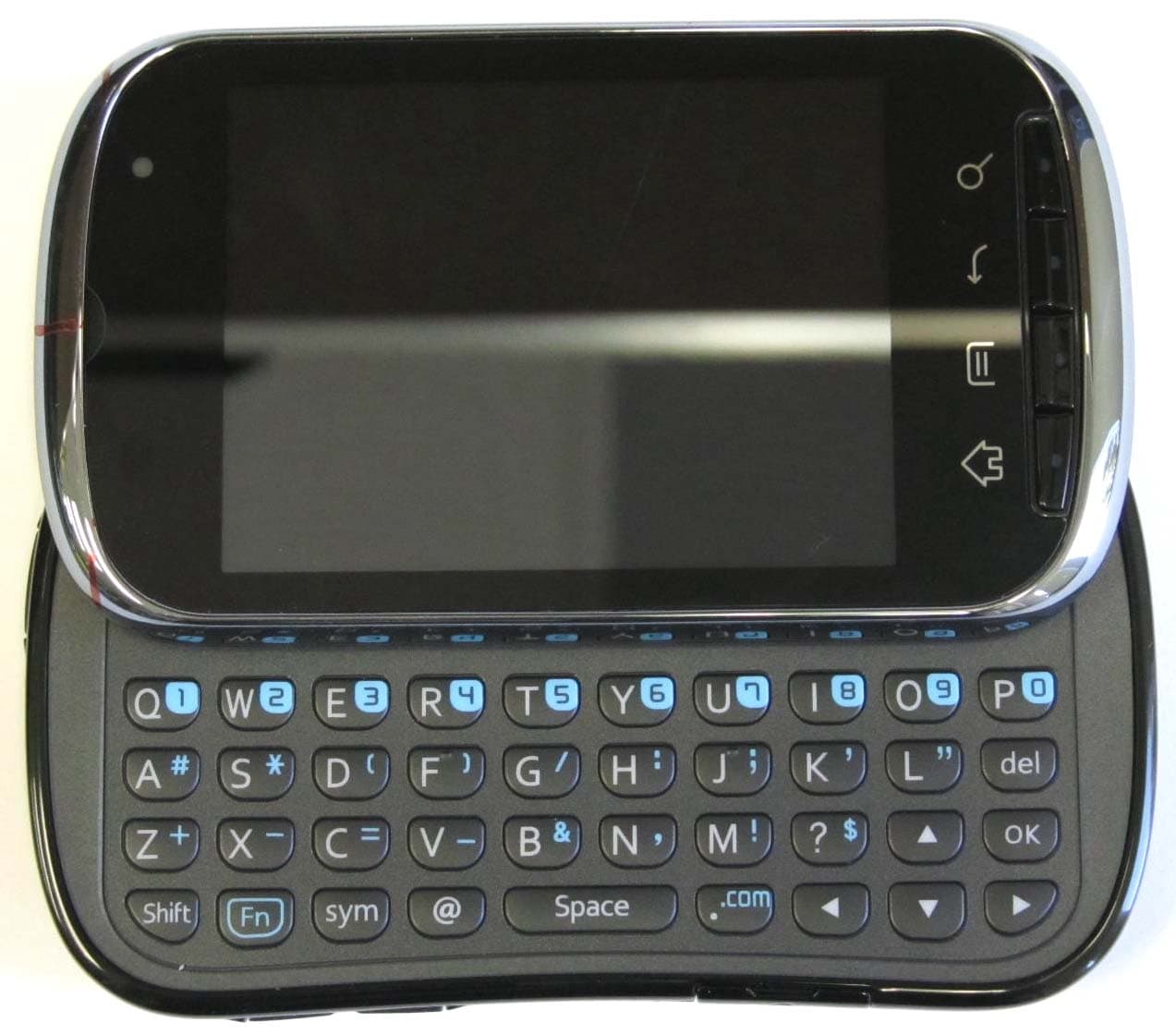
OVFC51213CD
Sep 01, 2011Tri-Band CDMA Mobile Phone with Bluetooth+WiFi
Equipment Class
DTS - Digital Transmission System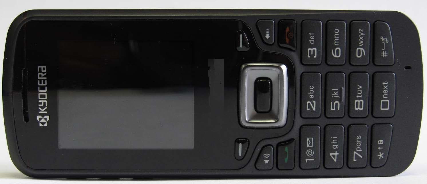
OVFS13503CB
May 17, 2011Tri-Band CDMA Phone
Equipment Class
PCE - PCS Licensed Transmitter held to ear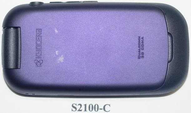
OVF-K5502
Jan 24, 2011Tri-Band CDMA Phone
Equipment Class
PCE - PCS Licensed Transmitter held to ear
OVF-K5501
Nov 07, 2010Single Band CDMA Cellular Phone with Bluetooth
Equipment Class
PCE - PCS Licensed Transmitter held to ear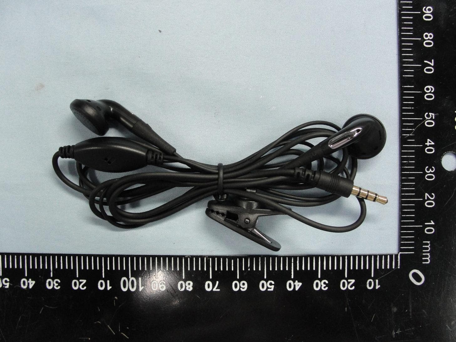
OVF-C4700
Aug 09, 2010Cellular/PCS WCDMA/GSM/GPRS/EDGE phone with Bluetooth
Equipment Class
PCE - PCS Licensed Transmitter held to ear