OVFKWC-M200Transmitter Module
Kyocera International, Inc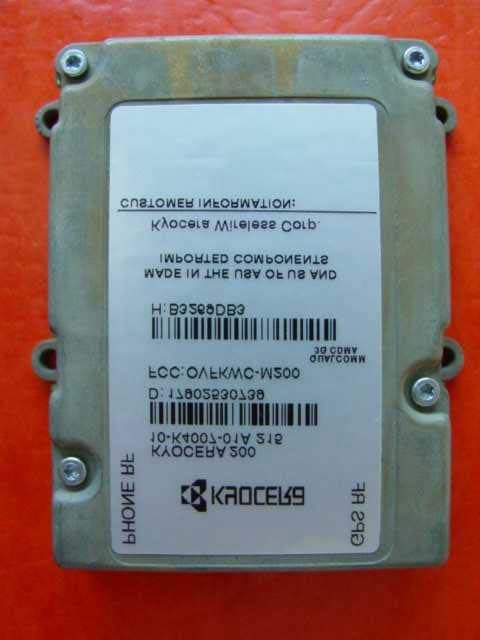
Click to zoom
Application Details
- Equipment Class
- PCB - PCS Licensed Transmitter
- Date of Grant
- Jul 21, 2003
- Application Purpose
- Original Equipment
- Date of Application
- Jul 21, 2003
- Equipment Note
- Transmitter Module
- Frequency Range
- 1851.25000000 - 1908.75000000
- Company
- Kyocera International, Inc
- Country
- United States
Documents & Files
Document Text
Text extracted from the exhibit documents filed with the FCC. Open a document above to read the original.
Users Manual
Kyocera 200 Module Data Book 82-B7907-1, Rev. 005 17 July, 2003 Kyocera Proprietary This technology is controlled by the United States Government. Diversion contrary to U.S. Law prohibited. Data and information contained in or disclosed by this document is proprietary information of Kyocera Wireless Corp. By accepting this material the recipient agrees that this material and the information contained therein is held in confidence and trust and will not be used, copied, reproduced in whole or in part, nor its contents revealed in any manner to others without the express written permission of Kyocera Wireless Corp. KYOCERA WIRELESS CORP. 10300 CAMPUS POINT DRIVE SAN DIEGO, CA 92121 Copyright © 2003 Kyocera Wireless Corp. All rights reserved. Printed in the United States of America. 82-B7907-1, Rev. 005 17 July, 2003 Kyocera Proprietary Kyocera ProprietaryKyocera 200 Module Data Bookiii Contents 1KYOCERA WIRELESS CORP.. . . . . . . . . . . . . . . . . . . . . . . . . . . . . . . . . . . . . . . . . . . . . . . . . . . . . . . . .1 Introduction . . . . . . . . . . . . . . . . . . . . . . . . . . . . . . . . . . . . . . . . . . . . . . . . . . . . . . . . . . . . . . . . . . . . . . . . . . . . . .1 Kyocera Corporation background. . . . . . . . . . . . . . . . . . . . . . . . . . . . . . . . . . . . . . . . . . . . . . . . . . . . . . . . . . . . . .1 Kyocera Wireless Corp. CDMA consumer products. . . . . . . . . . . . . . . . . . . . . . . . . . . . . . . . . . . . . . . . . . . . . . . .1 2CDMA AND CELLULAR FUNDAMENTALS . . . . . . . . . . . . . . . . . . . . . . . . . . . . . . . . . . . . . . . . . . . . . .3 CDMA . . . . . . . . . . . . . . . . . . . . . . . . . . . . . . . . . . . . . . . . . . . . . . . . . . . . . . . . . . . . . . . . . . . . . . . . . . . . . . . . . . .3 CDMA cocktail party example. . . . . . . . . . . . . . . . . . . . . . . . . . . . . . . . . . . . . . . . . . . . . . . . . . . . . . . . . . . . .4 How CDMA works. . . . . . . . . . . . . . . . . . . . . . . . . . . . . . . . . . . . . . . . . . . . . . . . . . . . . . . . . . . . . . . . . . . . . .4 Cellular frequency reuse patterns . . . . . . . . . . . . . . . . . . . . . . . . . . . . . . . . . . . . . . . . . . . . . . . . . . . . . . . . . .4 CDMA concept. . . . . . . . . . . . . . . . . . . . . . . . . . . . . . . . . . . . . . . . . . . . . . . . . . . . . . . . . . . . . . . . . . . . . . . . .5 CDMA versus analog FM . . . . . . . . . . . . . . . . . . . . . . . . . . . . . . . . . . . . . . . . . . . . . . . . . . . . . . . . . . . . . . . . .5 Spatial diversity . . . . . . . . . . . . . . . . . . . . . . . . . . . . . . . . . . . . . . . . . . . . . . . . . . . . . . . . . . . . . . . . . . . .6 Frequency diversity . . . . . . . . . . . . . . . . . . . . . . . . . . . . . . . . . . . . . . . . . . . . . . . . . . . . . . . . . . . . . . . . .6 Time diversity. . . . . . . . . . . . . . . . . . . . . . . . . . . . . . . . . . . . . . . . . . . . . . . . . . . . . . . . . . . . . . . . . . . . . .6 Synchronization. . . . . . . . . . . . . . . . . . . . . . . . . . . . . . . . . . . . . . . . . . . . . . . . . . . . . . . . . . . . . . . . . . . . . . . .7 Rake receiver. . . . . . . . . . . . . . . . . . . . . . . . . . . . . . . . . . . . . . . . . . . . . . . . . . . . . . . . . . . . . . . . . . . . . . . . . .7 CDMA reverse link power control. . . . . . . . . . . . . . . . . . . . . . . . . . . . . . . . . . . . . . . . . . . . . . . . . . . . . . . . . .8 Open loop power control . . . . . . . . . . . . . . . . . . . . . . . . . . . . . . . . . . . . . . . . . . . . . . . . . . . . . . . . . . . .8 Closed loop power control . . . . . . . . . . . . . . . . . . . . . . . . . . . . . . . . . . . . . . . . . . . . . . . . . . . . . . . . . . .8 Mobile power bursting . . . . . . . . . . . . . . . . . . . . . . . . . . . . . . . . . . . . . . . . . . . . . . . . . . . . . . . . . . . . . . . . . .9 CDMA system time. . . . . . . . . . . . . . . . . . . . . . . . . . . . . . . . . . . . . . . . . . . . . . . . . . . . . . . . . . . . . . . . . . . . . .9 Closed loop power control puncturing. . . . . . . . . . . . . . . . . . . . . . . . . . . . . . . . . . . . . . . . . . . . . . . . . . . . . .9 Walsh code spreading . . . . . . . . . . . . . . . . . . . . . . . . . . . . . . . . . . . . . . . . . . . . . . . . . . . . . . . . . . . . . . . . . .10 Respreading the short sequence . . . . . . . . . . . . . . . . . . . . . . . . . . . . . . . . . . . . . . . . . . . . . . . . . . . . . . . . . .10 Forward link channel format. . . . . . . . . . . . . . . . . . . . . . . . . . . . . . . . . . . . . . . . . . . . . . . . . . . . . . . . . . . . .11 CDMA reverse link physical layer . . . . . . . . . . . . . . . . . . . . . . . . . . . . . . . . . . . . . . . . . . . . . . . . . . . . . . . . .12 Reverse error protection . . . . . . . . . . . . . . . . . . . . . . . . . . . . . . . . . . . . . . . . . . . . . . . . . . . . . . . . . . . . . . . .12 64-ary modulation . . . . . . . . . . . . . . . . . . . . . . . . . . . . . . . . . . . . . . . . . . . . . . . . . . . . . . . . . . . . . . . . . . . . .12 Reverse channel long code spreading. . . . . . . . . . . . . . . . . . . . . . . . . . . . . . . . . . . . . . . . . . . . . . . . . . . . . .12 CDMA turn-on process . . . . . . . . . . . . . . . . . . . . . . . . . . . . . . . . . . . . . . . . . . . . . . . . . . . . . . . . . . . . . . . . . . . . .13 System access. . . . . . . . . . . . . . . . . . . . . . . . . . . . . . . . . . . . . . . . . . . . . . . . . . . . . . . . . . . . . . . . . . . . . . . . .13 Sync channel message . . . . . . . . . . . . . . . . . . . . . . . . . . . . . . . . . . . . . . . . . . . . . . . . . . . . . . . . . . . . . .13 Read the paging channel . . . . . . . . . . . . . . . . . . . . . . . . . . . . . . . . . . . . . . . . . . . . . . . . . . . . . . . . . . . . . . . .14 Paging channel messages. . . . . . . . . . . . . . . . . . . …
Text truncated - open the document above for the full version.
Users Manual
M o d u l e D e v e l o p e r ’ s K i t Kyocera ProprietaryKyocera 200 Module Data Book61 12Module Developer’sKit The Module Developer’s Kit (MDK) is used to assist in development of end-user applications for the CDMA Module. The MDK facilitates integration through the serial and digital codec pulse code modulation (PCM) interface options. Contents of the MDK are illustrated below. Module and Travel Charger* Audio Headset* 9-pin RS 232 Cable Assembly* Module Documentation CD-ROM MMCX-to-SMA Adapter (qty: 2) * Kit may include alternate components. Interface Board (qty: 2) 62Kyocera 200 Module Data BookKyocera Proprietary Module Developer’sKit82-B7907-1 Rev. 005 It should be clearly understood that the software in the MDK (specifically, the code in the Kyocera 200 Module User’s Guide, 82-B7908-1) is provided for sample purposes only. The MDK software is not warranted as the basis for a deployed implementation. W a r r a n t y a n d P r o d u c t S u p p o r t Kyocera ProprietaryKyocera 200 Module Data Book63 13Warranty and Product Support The KWC CDMA Module Developer’s Kit arrives having been tested as described in the Module Testing & Integration chapter. Testing should be duplicated at the integrator’s/customer’s facility. KWC can provide advice as to the type of test equipment needed. This Module testing should be separate from the testing to be performed on the end product (with the Module installed). KWC offers a warranty for the CDMA Module, from the date of shipment from KWC’s facility. This warranty provides the customer with a remedy for defective Modules within the warranty period and subject to all other warranty provisions. KWC requests that the integrator retain several Modules as backup in case of failure. It is assumed that you maintain a first level of returned Module testing in your QA department prior to returning the Module to KWC. This alleviates the question of whether the failure is in the Module or the end product. “No trouble found” (NTF) occurrences on Modules returned to KWC will result in fees. KWC reserves the right, at its own discretion, to repair, replace, or issue a trade credit for any defective Module under warranty. Warranty repair excludes warranty claims on products that have been subject to misuse, neglect, improper storage or installation, or that have been repaired, modified, or altered by a facility other than a KWC-authorized service center or a KWC-certified repair center. In all cases, the final testing of the KWC line is the sole controlling determination of Module performance. M e c h a n i c a l S p e c i f i c a t i o n s M e c h a n i c a l S p e c i f i c a t i o n s M e c h a n i c a l S p e c i f i c a t i o n s M e c h a n i c a l S p e c i f i c a t i o n s M e c h a n i c a l S p e c i f i c a t i o n s Kyocera ProprietaryKyocera 200 Module Data Book65 14Mechanical Specifications Mating connectors The following connectors mate with the Module. lModule Interface Connector Mate Manufacturer: MOLEX Inc., www.molex.com Manufacturer’s Part Number: 54230-0509 Kyocera MCN: 449-24545-0509 lModule RF Connector Mate Standard MMCX plug, available from several manufacturers including Amp, Radiall, and Telegartner Drawings The following technical drawings are included in this chapter: lLand pattern and pin assignment for Module interface mating connector lMounting hole and land pattern placement guidelines with recommended mounting hardware lModule overall dimensioned drawing lModule exploded view 66Kyocera 200 Module Data BookKyocera Proprietary Mechanical Specifications82-B7907-1 Rev. 005 Land pattern and pin assignment for the Module interface mating connector M e c h a n i c a l S p e c i f i c a t i o n s M e c h a n i c a l S p e c i f i c a t i o n s M e c h a n i c a l S p e c i f i c a t i o n s M e c h a n i c a l S p e c i f i c a t i o n s M e c h a n i c a l S p e c i f i c a t i o n s Kyocera ProprietaryKyocera 200 Module Data Book67 82-B7907-1 Rev. 005Mechanical Specifications Mounting hole and land pattern placement guidelines 68Kyocera 200 Module Data BookKyocera Proprietary Mechanical Specifications82-B7907-1 Rev. 005 Module outside dimensions (mm) M e c h a n i c a l S p e c i f i c a t i o n s M e c h a n i c a l S p e c i f i c a t i o n s M e c h a n i c a l S p e c i f i c a t i o n s M e c h a n i c a l S p e c i f i c a t i o n s M e c h a n i c a l S p e c i f i c a t i o n s Kyocera ProprietaryKyocera 200 Module Data Book69 82-B7907-1 Rev. 005Mechanical Specifications Module exploded view 70Kyocera 200 Module Data BookKyocera Proprietary Mechanical Specifications82-B7907-1 Rev. 005 A s s i g n m e n t s a n d S i g n a l D e f i n i t i o n s A s s i g n m e n t s a n d S i g n a l D e f i n i t i o n s A s s i g n m e n t s a n d S i g n a l D e f i n i t i o n s A s s i g n m e n t s a n d S i g n a l D e f i n i t i o n s A s s i g n m e n t s a n d S i g n a l D e f i n i t i o n s Kyocera ProprietaryKyocera 200 Module Data Book71 15Assignments and Signal Definitions 50-pin Module interface connector pin assignments (viewed looking down on connector) Signal definitions of 50-pin Module interface connector Pin #Signal NameCommentModem Signal Level 1VPH_PWRPower to the CDMA transceiver 3.6 VDC min to 4.2 VDC maxPower input (6) 2GNDSignal and power returnGROUND 3VPH_PWRPower to the CDMA transceiver 3.6 VDC min to 4.2 VDC maxPower input (6) 4GNDSignal and power returnGROUND 5VPH_PWRPower to the CDMA transceiver 3.6 VDC min to 4.2 VDC maxPower input (6) 6GNDSignal and power returnGROUND 7VPH_PWRPower to the CDMA transceiver 3.6 VDC min to 4.2 VDC maxPower input (6) 8GNDSignal and power returnGROUND 9VPH_PWRPower to the CDMA transceiver 3.6 VDC min to 4.2 VDC maxPower input (6) 10GNDSignal and power returnGROUND 11VEXT#Indicates that external power is being used 0 to VPH_PWR maxAnalog control 12N/CNo connection 13N/CNo connection 14LED_EN#Enable external LED0 to VPH_PWR maxAnalog control 15N/CNo connection 16LED_DRVExterna…
Text truncated - open the document above for the full version.
External Photos
Applicant: KWC Corp. FCC ID: OVFKWC-M200 3 Exhibit 17 Photographs Kyocera Wireless Corp. Series 200 Module Kyocera Wireless Corp. Series 200 Module Kyocera Wireless Corp. Series 200 Module Kyocera Wireless Corp. Series 200 Module Kyocera Wireless Corp. Series 200 Module
ID Label/Location Info
Applicant: KWC Corp. FCC ID: OVFKWC-M200 1 Exhibit 16 FCC Identification Label Information Applicant: KWC Corp. FCC ID: OVFKWC-M200 2
Internal Photos
Kyocera Wireless Corp. Series 200 Module Kyocera Wireless Corp. Series 200 Module Kyocera Wireless Corp. Series 200 Module Kyocera Wireless Corp. Series 200 Module
Operational Description
Applicant: KWC Corp.FCC ID: OVFKWC-M200 1 Exhibit 1 General Information – Operation Description 1.Production Plans Quantity Production Planned 2.Technical Description - Section 2.1033 (c) (1) The full name and mailing address of the manufacturer of the device and the applicant Applicant:Kyocera Wireless Corporation 10300 Campus Point Drive San Diego, CA 92121 Manufacture:Kyocera Wireless Corporation 10300 Campus Point Drive San Diego, CA92121 (2) FCC Identifier FCC ID: OVFKWC-M200 (3) User’s Manual See exhibit 18 (4) Types of Emission 40K0F8W 40K0F1D 1M25F9W F3E voice F3D supervisory audio tones, signaling tones F1D wideband data signal (5)Frequency range The frequency range of the equipment in Domestic Public Cellular Radio Telecommunications Service bands, 824 - 849 MHz and 869 - 894 MHz for FM and cellular CDMA. The channel spacing is 30 kHz for FM. The frequency range of the equipment in the Personal Communications Services (PCS) bands, 1850 – 1910 MHz and 1930 – 1990 MHz. The channel spacing is 1.25 MHz for CDMA. (6)Operating power levels The transmitter output power is independent of whether the equipment operates in the cellular system FM or CDMA mode, or PCS system CDMA mode. The equipment supports Class 3 Cellular Mobile Station Power Class, and Class 2 PCS Mobile Station Power Class. Its power output capability is reported to the Land Station via Station Class Mark. The equipment will respond to commands from Applicant: KWC Corp.FCC ID: OVFKWC-M200 2 the Land Station to change power levels as defined in the EIA/TIA/IS-98 and ANSI J-STD-018 Specification. (7)Maximum output power The equipment supports the maximum output power for Class 3 Cellular Mobile Station which is -2 dBW ERP for a FM mode and in the range of -7 dBW to 0 dBW ERP for a CDMA mode, and meets the 7 W ERP (+8.45 dBW) maximum power limitation of Section 22.913. The equipment supports the maximum output power for Class 2 PCS Mobile Station which is in the range of -7dBW to 0 dBW EIRP, and is within the limited 2 watts E.I.R.P. peak power of CFR 47 Part 24.232 (b). The equipment is able to limit the output power to the minimum necessary for successful communications. (8)Final RF amplifying device power consumption The equipment is powered by lithium ion rechargeable batteries which have a voltage range of 3.2 to 4.2 Vdc. In the Cellular band, the power consumption of the high power amplifier is about 27.8dBm in a CDMA mode and about 28.8dBm in a FM mode. In the PCS band, the power consumption of the high power amplifier is about 26.4dBm. (9) Tune-up procedure over the power range All frequency and power adjustments are set at the factory and there are no field adjustments for this product. Under digital mode, the frequency is locked to the base station and controlled by VCTCXO adjustments to offset any possible errors. Note: Digital mode encompasses the mobiles CDMA and FM operation. In CDMA, the carrier frequency error combiner combines the frequency error estimates of all in-lock demodulating fingers, and filters the result. This result drives a PDM circuit, which in turn yields a voltage that corrects the frequency of the VCTCXO. In FM, also referred to as digital FM, the frequency tracking loop circuit calculates the rate of rotation. This rate of rotation corresponds to the frequency error. This frequency error signal is filtered. This result drives a PDM circuit, which in turn yields a voltage that corrects the frequency of the VCTCXO. (10) Circuit description (a) Circuit diagram and list of semiconductor device See exhibit 14 and 15. (b) Circuit description for frequency determining and stabilizing The circuit provided for determining and stabilizing frequency is in exhibit 15. A voltage controlled, temperature compensated, crystal oscillator (VCTCXO) is employed as a frequency reference for all of the transceiver local oscillators. This crystal oscillator is specified to remain within +/- 2.5 ppm over temperature and voltage variations. The lock status indicator of all synthesizers is monitored by the microprocessor and an out of lock condition will inhibit transmission. In all modes, the mobile receiver monitors the received signal and adjusts the frequency of the VCTCXO, this corrects any errors between the mobile frequency and the base station transmitter. The mobile is locked to the base station. (c) Circuit description for spurious radiation suppression Applicant: KWC Corp.FCC ID: OVFKWC-M200 3 The circuit provided for suppression of spurious radiation is in exhibit 15. The transmitter front end provides filtering of the RF signal in order to meet FCC specifications. For radiated spurious suppression, proper design techniques and the use of proper shielding techniques reduced the emission levels well below the permissible FCC limit. (d) Circuit description for limiting modulation The circuit provided for limiting modulation is in exhibit 15. AMPS Mode The F3E audio modulation is accomplished through the use of Digital Signal Processor (DSP). Audio samples are output from the DFM block at 120Ksps. These samples are converted to 2’s complement form, Interpotated to 480Ksps rate , FM modulated, and Interpolated to the VCTCXO rate. The filtering and modulator require the VCTCXO clock along with the different enables, 120KHz, 240KHz, and 480KHz, all of which are generated from the VCTCXO reference. CDMA Mode when operating in a P_REV 5 or less network The CDMA mode described in the following pages is from the TIA/EIA/IS-95B Standard. The justification for the CDMA bandwidth of 1.25 MHz is that the chip rate is 1.2288 MHz. The 1.25MHz is measured at the 3dB down bandwidth. Channel spacing is normally set at this 1.25 MHz. For details, please refer to IS-95B, Section 6.1.3.10. Applicant: KWC Corp.FCC ID: OVFKWC-M200 4 CDMA MODE when operating in a P_REV 6 or above Network The CDMA mode described in the following pages is from IS-2000.2 Standard, Release 0, dated 24- April-2001. This specification is also know…
Text truncated - open the document above for the full version.
RF Exposure Info
Kyocera Module 200 FCC ID: OVFKWC-M200 MPE Distance Calculations The antenna gain was deduced from the conducted and radiated measurements. This was carried out for each antenna and for each frequency band. MPE distance calculations were carried out for the following, worst case, configurations: 1. Comvergance antenna, 824.04MHz (FM Low) 2. Comvergance antenna, 836.49MHz (FM Mid) The calculations are based on equation 3 of OET Bulletin 65. R = √ (PG/4πS) 1. R = √ (501.2 x 2.19/12.57) = 9.3cm 2. R = √ (508.2 x 1.88/12.57) = 8.7cm Derivation of Antenna Gain Antenna: Comvergance Freq MHz Conducted Output Power Radiated Output Power Gain (dBi) 824.04 (FM Low) 27.00 30.4 +3.4 836.49 (FM Mid) 27.06 29.8 +2.74 848.97 (FM Hi) 27.02 28.9 +1.88 824.70 (CDMA Low) 24.53 28.9 +4.37 836.49 (CDMA Mid) 24.57 29.5 +4.93 848.31 (CDMA Hi) 24.49 29.1 +4.61 1851.25 (PCS Low) 23.80 21.2 -2.6 1880.00 (PCS Mid) 23.85 21.9 -1.95 1908.75 (PCS Hi) 23.81 21.2 -2.61 Antenna: Bluetree Freq MHz Conducted Output Power Radiated Output Power Gain (dBi) 824.04 (FM Low) 27.00 21.2 -5.8 836.49 (FM Mid) 27.06 21.9 -5.16 848.97 (FM Hi) 27.02 22.7 -4.32 824.70 (CDMA Low) 24.53 20.8 -3.73 836.49 (CDMA Mid) 24.57 20.0 -4.57 848.31 (CDMA Hi) 24.49 20.2 -4.29 1851.25 (PCS Low) 23.80 21.8 -2.00 1880.00 (PCS Mid) 23.85 20.7 -3.15 1908.75 (PCS Hi) 23.81 21.1 -2.71 Antenna: IRD Freq MHz Conducted Output Power Radiated Output Power Gain (dBi) 824.04 (FM Low) 27.00 24.9 -2.10 836.49 (FM Mid) 27.06 24.3 -2.76 848.97 (FM Hi) 27.02 25.3 -1.72 824.70 (CDMA Low) 24.53 22.0 -2.53 836.49 (CDMA Mid) 24.57 19.9 -4.67 848.31 (CDMA Hi) 24.49 20.0 -4.49 1851.25 (PCS Low) 23.80 19.0 -4.8 1880.00 (PCS Mid) 23.85 17.3 -6.55 1908.75 (PCS Hi) 23.81 16.8 -7.01 Antenna: Orion Freq MHz Conducted Output Power Radiated Output Power Gain (dBi) 824.04 (FM Low) 27.00 23.2 -3.8 836.49 (FM Mid) 27.06 21.5 -5.56 848.97 (FM Hi) 27.02 21.1 -5.92 824.70 (CDMA Low) 24.53 22.1 -2.43 836.49 (CDMA Mid) 24.57 19.7 -4.87 848.31 (CDMA Hi) 24.49 18.7 -5.79 1851.25 (PCS Low) 23.80 18.2 -5.6 1880.00 (PCS Mid) 23.85 19.5 -4.35 1908.75 (PCS Hi) 23.81 20.8 -3.01 Antenna: Galtronics Freq MHz Conducted Output Power Radiated Output Power Gain (dBi) 824.04 (FM Low) 27.00 26.4 -0.6 836.49 (FM Mid) 27.06 25.3 -1.76 848.97 (FM Hi) 27.02 25.4 -1.62 824.70 (CDMA Low) 24.53 25.2 +0.67 836.49 (CDMA Mid) 24.57 24.4 -0.17 848.31 (CDMA Hi) 24.49 24.6 +0.11 1851.25 (PCS Low) 23.80 25.3 +1.5 1880.00 (PCS Mid) 23.85 25.3 +1.45 1908.75 (PCS Hi) 23.81 25.4 +1.59
Test Report
TÜV AMERICA, INC. 10040 Mesa Rim Road San Diego, CA 92121-2912 Phone 858 546 3999 FAX 858 546 0364 Report No. SC303100-03 Page 1 of 27 Rev.No 1.0 MEASUREMENT AND TECHNICAL REPORT KYOCERA WIRELESS CORPORATION 6455 Lusk Boulevard San Diego, CA 92121 DATE: 11 July 2003 This Report Concerns: Original Grant: X Class II Change: Equipment Type: Kyocera Module 200 Deferred grant requested per 47 CFR 0.457(d)(1)(ii)? Yes: Defer until: No: X Company Name agrees to notify the Commission by: N/A of the intended date of announcement of the product so that the grant can be issued on that date. Transition Rules Request per 15.37? Yes: No: X* (*) FCC Part 22, Paragraph(s) 22.917(b)(2) (*) FCC Part 24, Paragraph(s) 24.238(a) Report Prepared by: TÜV AMERICA, INC 10040 Mesa Rim Road San Diego, CA 92121-2912 Phone: 858 546 3999 Fax: 858 546 0364 TÜV AMERICA, INC. 10040 Mesa Rim Road San Diego, CA 92121-2912 Phone 858 546 3999 FAX 858 546 0364 Report No. SC303100-03 Page 2 of 27 Rev.No 1.0 TABLE OF CONTENTS Pages 1.0 GENERAL INFORMATION 3 1.1 Product Description 3 1.2 Related Submittal Grant 3 1.3 Tested System Details 3 1.4 Test Methodology 3 1.5 Test Facility 3 1.6 Part 2 Requirements 3 2.0 SYSTEM TEST CONFIGURATION 4 2.1 Justification 4 2.2 EUT Exercise Software 4 2.3 Special Accessories 4 2.4 Equipment Modifications 4 2.5 Configuration of Test System 4 3.0 RADIATED SPURIOUS EMISSIONS EQUIPMENT/DATA 5 - 26 4.0 ATTESTATION STATEMENT 27 TÜV AMERICA, INC. 10040 Mesa Rim Road San Diego, CA 92121-2912 Phone 858 546 3999 FAX 858 546 0364 Report No. SC303100-03 Page 3 of 27 Rev.No 1.0 1.0 GENERAL INFORMATION 1.1 Product Description Not Available 1.2 Related Submittal Grant None 1.3 Tested System Details The FCC ID’s for all equipment, plus descriptions of all cables used in the tested system are: None 1.4 Test Methodology Purpose of Test: To demonstrate compliance with the following tests. TEST FCC CFR 47# PASS/FAIL Radiated Spurious Emissions 22.917(b)(2) 24.238(a) Pass Pass Both Conducted and Radiated testing were performed according to the procedures in FCC/ANSI C63.4 and CSA 108.8-M1983. Radiated testing was performed at an antenna-to-EUT distance of 3 meters. 1.5 Test Facility The open area test site and conducted measurement data were tested by: TÜV AMERICA, INC 10040 Mesa Rim Road San Diego, CA 92121-2912 Phone: 858 546 3999 Fax: 858 546 0364 The Test Site Data and performance comply with ANSI C63.4 and are registered with the FCC, 7435 Oakland Mills Road, Columbia Maryland 21046. All Measurement Data is acquired according to the content of FCC Measurement Procedure and ANSI C63.4, unless supplemented with additional requirements as noted in the test report. 1.6 Part 2 Requirements (Remove if Part 15 or 18) TÜV AMERICA, INC. 10040 Mesa Rim Road San Diego, CA 92121-2912 Phone 858 546 3999 FAX 858 546 0364 Report No. SC303100-03 Page 4 of 27 Rev.No 1.0 2.0 SYSTEM TEST CONFIGURATION 2.1 Justification The EUT was initially tested for FCC emissions in the following configuration: See Test Setup Photos Exhibit 2.2 EUT Exercise Software None 2.3 Special Accessories None 2.4 Equipment Modifications None 2.5 Configuration of Test System See Test Setup Photos Exhibit TÜV AMERICA, INC. 10040 Mesa Rim Road San Diego, CA 92121-2912 Phone 858 546 3999 FAX 858 546 0364 Report No. SC303100-03 Page 5 of 27 Rev.No 1.0 3.0 RADIATED SPURIOUS EMISSIONS EQUIPMENT/DATA See following page(s). TÜV AMERICA, INC. 10040 Mesa Rim Road San Diego, CA 92121-2912 Phone 858 546 3999 FAX 858 546 0364 Report No. SC303100-03 Page 6 of 27 Rev.No 1.0 Test Conditions: RADIATED SPURIOUS EMISSIONS: FCC Part 22.917(b)(2) and Part 24.238(a) The RADIATED SPURIOUS EMISSIONS measurements were performed at the San Diego Testing Facility: oo - Test not applicable n - Roof (Small Open Area Test Site) Testing was performed at a test distance of: n - 3 meters Test Equipment Used: Model No. Prop. No. Description Manufacturer Serial No. Date Cal’ed HP8566B 720 Spectrum Analyzer Hewlett Packard 2115A00842 09/02 AMF-5D-010180-35-10P 719 PreAmplifier Miteq 549460 NCR* 3115 251 Double Ridge Horn Antenna EMCO 2495 12/02 FF 6548-2 783 2000 MHz High Pass Filter Sage 008 NCR* FF 6548-1 778 900 MHz Low Pass Filter Sage 005 NCR* 3115 453 Horn Antenna Electro Mechanics Co 3564 01/03 8481A 554 Power Sensor Hewlett Packard 1926A27807 09/02 436A 775 Power Meter Hewlett Packard 1918A05312 09/02 8350B/85592C 6707 Sweep Oscillator/Signal Generator Hewlett Packard 2328A00112 NCR* 3146 243 Log Periodic Antenna EMCO 106X 05/03 DM-105-T3 226 Dipole Antenna EMCO 6666 02/03 Remarks: One year calibration cycle for all test equipment and sites. (*) No Calibration Required. TÜV AMERICA, INC. 10040 Mesa Rim Road San Diego, CA 92121-2912 Phone 858 546 3999 FAX 858 546 0364 Report No. SC303100-03 Page 7 of 27 Rev.No 1.0 TÜV AMERICA, INC. 10040 Mesa Rim Road San Diego, CA 92121-2912 Phone 858 546 3999 FAX 858 546 0364 Report No. SC303100-03 Page 8 of 27 Rev.No 1.0 TÜV AMERICA, INC. 10040 Mesa Rim Road San Diego, CA 92121-2912 Phone 858 546 3999 FAX 858 546 0364 Report No. SC303100-03 Page 9 of 27 Rev.No 1.0 TÜV AMERICA, INC. 10040 Mesa Rim Road San Diego, CA 92121-2912 Phone 858 546 3999 FAX 858 546 0364 Report No. SC303100-03 Page 10 of 27 Rev.No 1.0 TÜV AMERICA, INC. 10040 Mesa Rim Road San Diego, CA 92121-2912 Phone 858 546 3999 FAX 858 546 0364 Report No. SC303100-03 Page 11 of 27 Rev.No 1.0 TÜV AMERICA, INC. 10040 Mesa Rim Road San Diego, CA 92121-2912 Phone 858 546 3999 FAX 858 546 0364 Report No. SC303100-03 Page 12 of 27 Rev.No 1.0 TÜV AMERICA, INC. 10040 Mesa Rim Road San Diego, CA 92121-2912 Phone 858 546 3999 FAX 858 546 0364 Report No. SC303100-03 Page 13 of 27 Rev.No 1.0 TÜV AMERICA, INC. 10040 Mesa Rim Road San Diego, CA 92121-2912 Phone 858 546 3999 FAX 858 546 0364 Report No. SC303100-03 Page 14 of 27 Rev.No 1.0 TÜV AMERICA, INC. 10040 Mesa Rim Road San Diego, CA 92121-2912 Phone 858 546 3999 FAX 858 546 0364 Report No. SC303100-03 Page 15 of 27 Rev.No 1.0 TÜV AMERICA, IN…
Text truncated - open the document above for the full version.
Test Report
Applicant: KWC Corp.FCC ID: OVFKWC-M200 Exhibit 12 Occupied Bandwidth and Spurious Emission Measured Data -- for CDMA mode when operating in P_REV 6 or above KWC module 200 (M2) supports additional reverse channels, as per IS-98D, additional measurements have taken to show compliance. Below is the applicable section from IS-98D 4.5 Limitations on Emissions 4.5.1 Conducted Spurious Emissions 4.5.1.1 Definition Conducted spurious emissions are emissions at frequencies that are outside the assigned CDMA Channel, measured at the mobile station antenna connector. This test measures the spurious emissions during continuous transmission. 4.5.1.2 Method of Measurement 1. Connect the base station to the mobile station antenna connector as shown in Figure 6.5.1-4. The AWGN generator and the interference generator are not applicable in this test. Connect a spectrum analyzer (or other suitable test equipment) to the mobile station antenna connector. 2. For each band class and radio configuration that the mobile station supports, configure the base station and mobile station to operate in that band class and perform steps 3 through 17. • Thus Band Class 0 and Band Class 1 for the M2 3. Set the following parameters of the Access Parameters Message as specified below: ParameterValue (Decimal) NOM_PWR 7 (7 dB) INIT_PWR 15 (15 dB) PWR_STEP7 (7 dB/step) NUM_STEP15 (16 probes/sequence) MAX_RSP_SEQ15 (15 sequences) If the Enhanced Access Channel is used, set the following parameters of the Enhanced Access Parameters Message as specified below (N/A so Table not included below) 4. If the mobile station supports Reverse Traffic Channel Radio Configuration 1 and Forward Traffic Channel Radio Configuration 1, set up a call using Fundamental Channel Test Mode 1 (see 1.3) with 9600 bps data rate only and perform steps 15 through 17. • Test Mode 1 implies an S02 call(Rate Set 1) on RC1/RC2....this is equivalent to what was performed already h-1 through h-4 of Exhibit 8 and a, b, c, and d of Exhibit 9 5. If the mobile station supports the Radio Configuration 3 Reverse Fundamental Channel and demodulation of Radio Configuration 3, 4, or 5, set up a call using Fundamental Channel Test Mode 3 (see 1.3) with 9600 bps data rate only and perform steps 15 through 17. • Test Mode 3 implies using a Rate Set 1 loopback service option. 6. If the mobile station supports the Radio Configuration 3 Reverse Dedicated Control Channel and demodulation of Radio Configuration 3, 4, or 5, set up a call using Dedicated Control Channel Test Mode 3 (see 1.3) with 9600 bps data rate only and 100% frame activity and perform steps 15 through 17. • N/A, the M2 will not support F/R-DCCH Applicant: KWC Corp.FCC ID: OVFKWC-M200 7. If the mobile station supports the Radio Configuration 3 Reverse Fundamental Channel, Radio Configuration 3 Reverse Dedicated Control Channel and demodulation of Radio Configuration 3, 4, or 5, set up a call using Fund…
Text truncated - open the document above for the full version.
Contact Information
Applicant
Thuy To(Regulatory Affairs Manager)
Test Firm
TUV AmericaJames Owen
Technical Specifications
| # | Rule Parts | Frequency Range | Power Output | Emission | Tolerance |
|---|---|---|---|---|---|
| 4 | 24E | 1.85 GHz - 1.91 GHz | 350.00 mW | 1M25F9W | 2.5 ppm |
Other Applications from Kyocera International, Inc
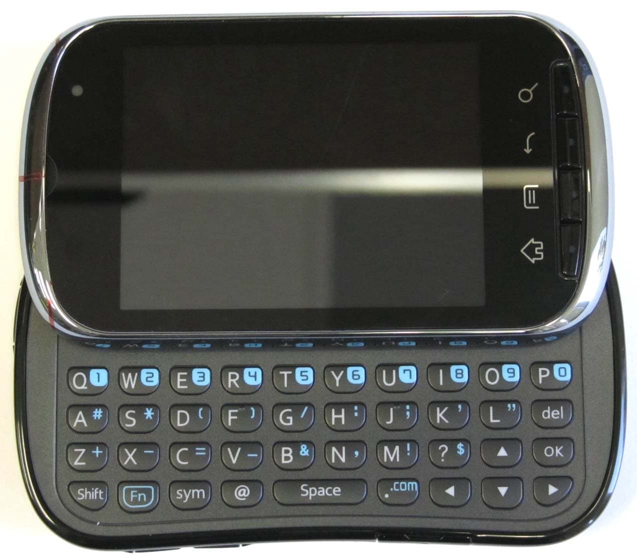
OVFC51213CD
Sep 01, 2011Tri-Band CDMA Mobile Phone with Bluetooth+WiFi
Equipment Class
DTS - Digital Transmission System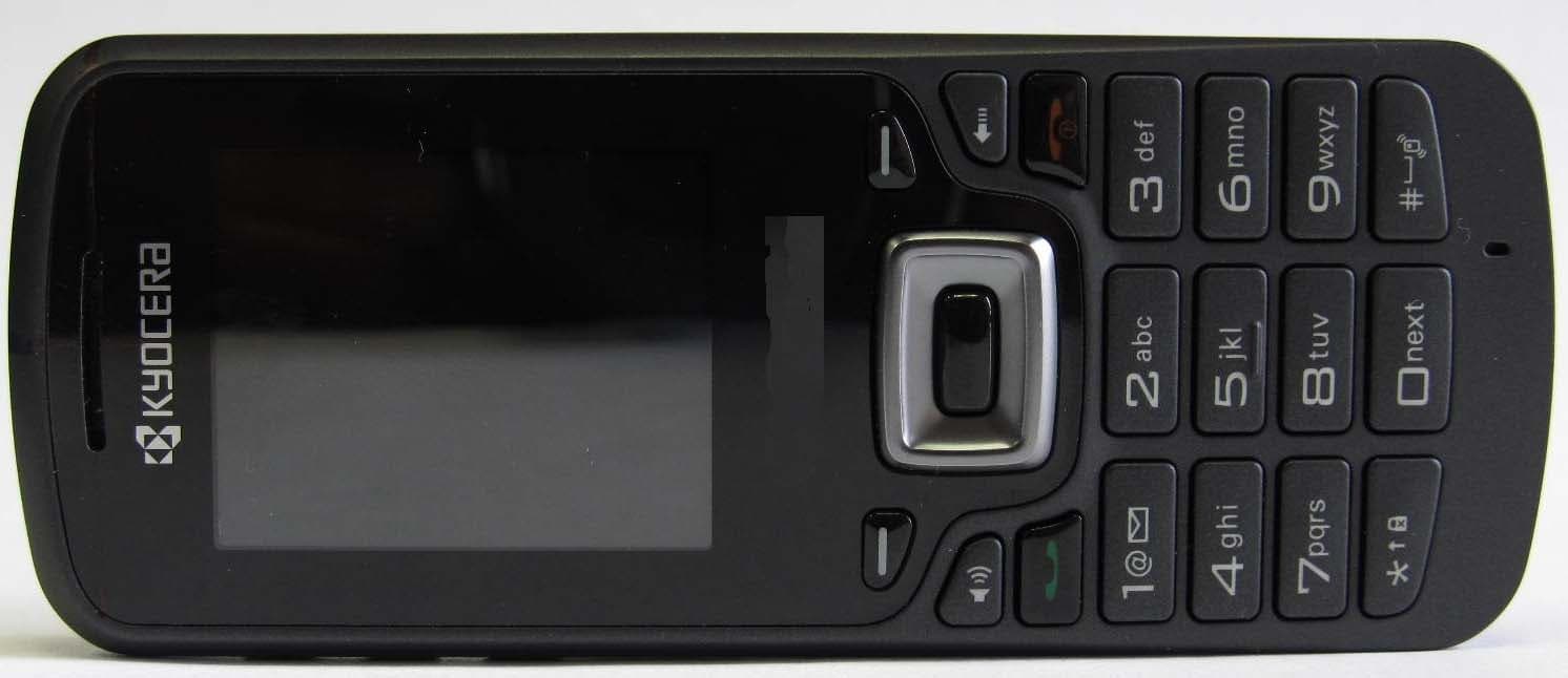
OVFS13503CB
May 17, 2011Tri-Band CDMA Phone
Equipment Class
PCE - PCS Licensed Transmitter held to ear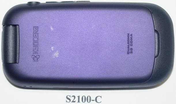
OVF-K5502
Jan 24, 2011Tri-Band CDMA Phone
Equipment Class
PCE - PCS Licensed Transmitter held to ear
OVF-K5501
Nov 07, 2010Single Band CDMA Cellular Phone with Bluetooth
Equipment Class
PCE - PCS Licensed Transmitter held to ear
OVF-C4700
Aug 09, 2010Cellular/PCS WCDMA/GSM/GPRS/EDGE phone with Bluetooth
Equipment Class
PCE - PCS Licensed Transmitter held to ear