OVFTXRTR10012Kyocera KR2 Mobile Router
Kyocera International, Inc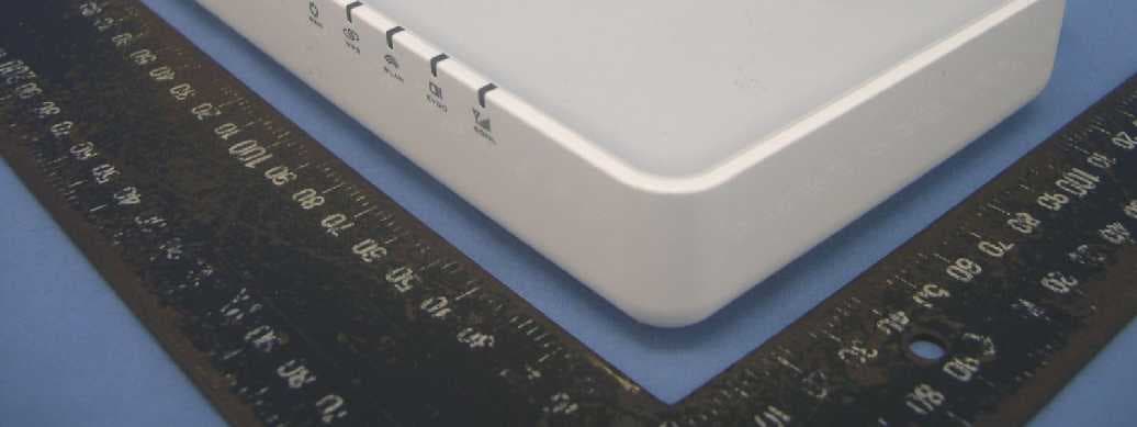
Click to zoom
Application Details
- Equipment Class
- DTS - Digital Transmission System
- Date of Grant
- Jan 29, 2008
- Application Purpose
- Original Equipment
- Date of Application
- Jan 29, 2008
- Equipment Note
- Kyocera KR2 Mobile Router
- Frequency Range
- 2412.00000000 - 2462.00000000
- Company
- Kyocera International, Inc
- Country
- United States
Documents & Files
Document Text
Text extracted from the exhibit documents filed with the FCC. Open a document above to read the original.
Users Manual
WELCOME Welcome to your Kyocera KR2 Mobile Router(KR2)! Now you can create a WiFi ® hotspot, and make your network completely mobile using a EVDO enabled cellular handset or modem, or a 1xEV-DO Express Card or PC Card. A cable/DSL modem can also be used while stationary. Features System Requirements Getting to Know Your KR2 LEDs (Front View) Connections and Controls (Back View) Controls (Top View) USB, Express Card, or PC Card Connection (Left Side View) •USB Port 2: Data connection point for 1xEV-DO supported handsets and modems. • Express Card Slot: Data connection point for 1xEV-DO Express Cards. • PC Card Slot: Data connection point for 1xEV-DO PC Cards. Before you Begin–Antenna Considerations Antenna Location and Position Caution: To ensure proper KR2 operation, please use care when positioning antennas. Wireless signals are sensitive to interference such as walls, floors, metal objects, and other large objects. Prior to installation, locate and place the KR2 in an area of least resistance. After installing the KR2 it may be useful to adjust the antennas for maximum coverage of your work area. 1xEV-DO Signal Strength Monitoring Activate Signal Strength Mode: Press and hold the SGNL Button during power ON to activate SGNL Mode. Deactivate Signal Strength Mode: Press and hold the SGNL Button again to exit SGNL Mode, and return the KR2 to normal operations. 1. Connecting Your KR2 to the Internet There is no software to install. Simply follow the steps for your desired connection below. Wired WAN Connection (Cable Modem or DSL Modem) If using a wired WAN connection, connect through the blue wired WAN Port located on the back side of the KR2. The WA N L E D will illuminate green when your network is active and connected. 1xEV-DO Device Connection Connect your 1xEV-DO supported device through your a USB Port, Express Card Slot, or PC Card Slot. With most devices, a connection will be automatically established. The EVDO LED will illuminate green indicating your wireless network is now ready. Note: Not all cards and modems are compatible. (For a list of compatible devices please our website at: www.kyocera-wireless.com/support). Some handsets require you to change settings to allow your handset to act as a modem (consult your handset documentation for additional information). 2. Establishing a LAN Connection–WiFi ® or Wired When powered ON, the KR2 serves as an active WiFi ® access point. Any WiFi ® 802.11b/g/n enabled device can associate with the KR2. Up to 32 others can associate with your wireless network (unless restricted by your cellular service provider). By default, no password is required to access network resources. Note:If using a WPS supported device you may push the WPS Button to synchronize with the KR2. KR2 WPS supports PIN and button operations. 3. Using the KR2 Setup Wizard–Establish Security After establishing a KR2 connection, navigate to the <Basic> tab of the Admin/Setup pages. From this tab you run the built in Setup Wizard to set your time zone, create your own unique password, change the network SSID (KR2 broadcast name), and establish network security. Congratulations! Your Kyocera KR2 Mobile Router setup is complete and ready for use. FACTORY RESET All settings on the KR2 will revert to their default state after a factory reset has been completed. The network name (SSID) and login password will return to their default values (located on the product label on the bottom of the KR2) Caution: Please ensure you have recorded personalized security settings before proceeding. 1- Locate the RESET Button (small hole) located on the back side of the KR2. Using the end of a paperclip, insert, press, and hold the RESET Button while simultaneously replugging in the KR2. 2- Continue holding the RESET Button until the Power LED and LEDs 1-4 blink ON and OFF. 3- Your KR2 factory settings will then be restored. SPECIFICATIONS •LAN Interface: WiFi ® 802.11b,/g/n (highest level of security), connection speed up to 300 Mbps, 3 antennas, and 4 Ethernet ports. • Wireless Security: 64bit or 128bit WEP encryption, WPA-PSK authentication, WPS (WiFi ® Protected Setup). • Connection Failover: WAN to 1xEV-DO cellular connection. • LAN Security: NAT with DHCP, PPTP VPN Pass through, MAC Filtering, IP Filtering, and Filter Scheduling. • Device Management: Web based browser for advanced users: Internet Explorer, Firefox, or other JavaScript enabled browsers. •VPN: Pass through is set by default. • A USB cellular handset or modem, or 1xEV-DO ExpressCard, or PC Card (for a list of compatible devices please our website at: www.kyocera-wireless.com/support). • Mozilla Firefox 2.0.0.11 or later, Internet Explorer 6 or later, Netscape Navigator 9 or later, Safari 3 Beta or later, or Opera 9.24 or later. 1- Power: •Green –KR2 is powered ON. ( Power LED and LEDs 1-4 blink green during KR2 initialization). 2- LAN 1-4: •Green–Connected and active. 3- WAN (Wired WAN): •Green–Connected and active. 4- WPS(WiFi ® Protected Setup): •Green–WPS negotiation is taking place. • Blinking Orange–WPS is in process. • Blinking Red–Session overlap or error. 5- WLAN (WiFi ® is ON and operating correctly): •Green–WiFi ® is enabled. • Blinking Green–WiFi ® traffic is active. 6- EVDO: •Green–1xEV-DO PC Card or Express Card, or USB cellular handset or modem is connected and active. • Blinking Green–WiFi ® traffic is active. 7- SGNL (Signal Strength Mode): • Please see “1xEV-DO Signal Strength Monitoring” for LED mode information. 1- Power : AC Adapter Jack. 2- RESET Button: Press and hold while powering ON to initialize factory default settings. 3- USB Port 1: Data connection point for supported handsets and modems. 4- WAN Port: Data connection point for hard-wired Ethernet port (cable or DSL modem). 5- LAN 1-4 Ports: Data connection point for Ethernet LAN ports (local connections). 6- Wireless ON/OFF Switch: Enables or disables WiFi ® . 1- WPS Button: Activates WiFi ® Protected Setup (WPS) for WPS enabled devices. 2- SGNL …
Text truncated - open the document above for the full version.
Attestation Statements
KYOCERA WIRELESS CORP. 10300 CAMPUS POINT DRIVE SAN DIEGO, CA 92121 Channel Attestation Page 1 of 1 January 11, 2008 Channel Attestation To Whom It May Concern: We, Kyocera Wireless Corp. declares that device does not have “Ad Hoc on non-US frequencies” and/or “on DFS frequencies” while applying for the follow product. Model Number: TXRTR10012 Trademark: Kyocera Wireless Corp. Product name: Kyocera KR2 Mobile Router If you have any questions regarding the authorization, please don’t hesitate to contact us. Sincerely, C. K. Li Hardware Engineer, Principal Kyocera Wireless Corp. Tel. : 1-858-882-3945
Cover Letter(s)
KYOCERA WIRELESS CORP. 10300 CAMPUS POINT DRIVE SAN DIEGO, CA 92121 Request of Confidentiality Page 1 of 1 January 11, 2008 Federal Communications Commission Authorization and Evaluation Division 7435 Oakland Mills Road Columbia, Maryland 21046 Re: Request of Confidentiality for FCC ID: OVFTXRTR10012 To Whom It May Concern: Pursuant to Sections 0.457 and 0.459 of the Commission’s Rules (CFR 47), Kyocera Wireless Corp (KWC) hereby requests confidential and treatment of information accompanying this Application. The materials contain trade secrets and proprietary information not customarily released to the public. The public disclosure of these matters might be harmful to the Applicant and provide unjustified benefits to its competitors. We are also requesting Short-Term Confidentiality as outlined in Public Notice DA 04-1705. This provision will give KWC Temporary Confidentiality of commercially sensitive information prior to product launch. The requested Confidential and Temporary Confidential exhibits are listed in table 1 below: Table 1. Confidential and Short-Term Confidential Request Description Operational Description Block diagrams Confidential Schematics Instruction Manual External Photos Internal Photos Short-Term Confidential Test Setup Photos The Applicant understands that pursuant to Rule 0.457, disclosure of this Application and all accompanying documentation will not be made before the date of the Grant for this Application. Sincerely, C. K. Li Hardware Engineer, Principal Kyocera Wireless Corp. Tel. : 1-858-882-3945
Cover Letter(s)
KYOCERA WIRELESS CORP. 10300 CAMPUS POINT DRIVE SAN DIEGO, CA 92121 Authorization Letter Page 1 of 1 January 11, 2008 Letter of Authorization To Whom It May Concern: We, the undersigned, hereby authorize Advance Data Technology Corporation (ADT) of Taiwan to act on our behalf in all matters relating to applications for equipment authorization, including signing of all documents relating to these matters. Any and all acts carried out by ADT on our behalf shall have the same effects as acts of our own. We also hereby certify that we are not subject to a denial of Federal benefits, that include FCC benefits, pursuant to Section 5301 of the Anti-Drug Abuse Act of 1988, 21 U.S.C. 862. The authorization for ADT to act on Kyocera’s behalf is limited by the following conditions: 1. This authorization is extended only to Kyocera Regulatory Model Number: TXRTR10012. 2. This authorization is extended only for FCC and IC certifications. 3. Certificates and test reports generated on Kyocera’s behalf must be emailed or copied to my attention when completed. 4. No access should be granted to any existing Kyocera file or project information. This authorization is valid for a period of one year from the date of this letter. Sincerely, C. K. Li Hardware Engineer, Principal Kyocera Wireless Corp. Tel. 䰆 1-858-882-3945 C K Li Digitally signed by C K Li DN: CN = C K Li, C = US, O = Kyocera Wireless Corp. Reason: I attest to the accuracy and integrity of this document Date: 2008.01.11 15:48:43 -08'00'
External Photos
Page 1 CONSTRUCTION PHOTOS OF EUT
External Photos
FCC ID:OVFTXRTR10012 FCC LABEL LOCATION The label will be permanently affixed at a conspicuous location on the device. Label
ID Label/Location Info
MADEINTAIWAN P/N:65-R2900-01 WLAN MAC ID:xxxxxxxxxxxx DATE CODE:YWWC-001 TXRTR10012 S/N: xxxxxxxxxxxx KYOCERA KR2 MobileRouter FCC ID: OVFTXRTR10012 IC: 3572A-TXRTR10012 WPS PIN:xxxxxxxx 9-12VDC/1.5A RoHS http://192.168.0.1
Internal Photos
Page 2 Page 3 Page 4 Page 5 Page 6 Page 7 Page 8 Page 9 Model No.: MU18-2120150-A1 Page 10 Model No.: Au-79Dmu Page 11
RF Exposure Info
Report No.: SA970103H02 1 RF EXPOSURE REPORT REPORT NO.: SA970103H02 MODEL NO.: TXRTR10012 ACCORDING: FCC Guidelines for Human Exposure IEEE C95.1 APPLICANT: Kyocera Wireless Corp. ADDRESS: 10300 Campus Point Drive San Diego, CA 92121 ISSUED BY: Advance Data Technology Corporation LAB LOCATION: No. 81-1, Lu Liao Keng, 9 Ling, Wu Lung Tsuen, Chiung Lin Hsiang, Hsin Chu Hsien, Taiwan, R.O.C. Report No.: SA970103H02 2 RF Exposure Measurement 1. Introduction In this document, we try to prove the safety of radiation harmfulness to the human body for our product. The limit for Maximum Permissible Exposure (MPE) specified in FCC 1.1310 is followed. The Gain of the antenna used in this product is measured in a Fully Anechoic Chamber (FAC) calibrated for antenna measurement in ADT, and also the maximum total power input to the antenna is measured. Through the Friis transmission formula and the maximum gain of the antenna, we can calculate the distance, away from the product, where the limit of MPE is reached. Although the Friis transmission formula is a far field assumption, the calculated result of that is an over-prediction for near field power density. We will take that as the worst case to specify the safety range. 2. RF Exposure Limit According to FCC 1.1310: The criteria listed in the following table shall be used to evaluate the environmental impact of human exposure to radio-frequency (RF) radiation as specified in 1.1307(b) LIMITS FOR MAXIMUM PERMISSIBLE EXPOSURE (MPE) Frequency Range (MHz) Electric Field Strength (V/m) Magnetic Field Strength (A/m) Power Density (mW/cm 2 ) Average Time (minutes) (A)Limits For Occupational / Control Exposures 300-1500 ... ... F/300 6 1500-100,000 ... ... 5 6 (B)Limits For General Population / Uncontrolled Exposure 300-1500 ... ... F/1500 6 1500-100,000 ... ... 1.0 30 F = Frequency in MHz Report No.: SA970103H02 3 3. Friis Formula Friis transmission formula : Pd = (Pout*G) / (4*pi*r 2 ) where Pd = power density in mW/cm 2 Pout = output power to antenna in mW G = gain of antenna in linear scale Pi = 3.1416 R = distance between observation point and center of the radiator in cm Pd is the limit of MPE, 1 mW/cm 2 . If we know the maximum Gain of the antenna and the total power input to the antenna, through the calculation, we will know the MPE value at distance 20cm. Ref. : David K. Cheng, Field and Wave Electromagnetics, Second Edition, Page 640, Eq. (11-133). 4. EUT Operating condition The software provided by client enabled the EUT to transmit and receive data at specific channel frequencies individually. 5. Classification The antenna of this product, under normal use condition, is at least 20cm away from the body of the user. Warning statement to the user for keeping at least 20cm or more separation distance with the antenna should be included in users manual. So, this device is classified as Mobile Device Report No.: SA970103H02 4 6. Test Results 6.1 Antenna Gain There are three antennas provided to this EUT, please refer to the following table: Transmitter Circuit Antenna Type Antenna Connector Gain(dBi) Chain(0) Dipole IPEX 4 Chain(1) Dipole IPEX 4 Chain(2) Dipole IPEX 4 6.2 Output Power Into Antenna & RF Exposure value at distance 20cm: For Part 802.11b Channel Channel Frequency (MHz) Output Power to Antenna (mW) Power Density (mW/cm 2 ) Limit of Power Density (mW/cm 2 ) 1 2412 63.096 0.032 1.0 6 2437 83.176 0.042 1.0 11 2462 53.703 0.027 1.0 For Part 802.11g Channel Channel Frequency (MHz) Output Power to Antenna (mW) Power Density (mW/cm 2 ) Limit of Power Density (mW/cm 2 ) 1 2412 80.168 0.040 1.0 6 2437 107.647 0.054 1.0 11 2462 53.580 0.027 1.0 DRAFT 802.11n (20MHz) OFDM Channel Channel Frequency (MHz) Output Power to Antenna (mW) Power Density (mW/cm 2 ) Limit of Power Density (mW/cm 2 ) 1 2412 65.857 0.033 1.0 6 2437 67.995 0.034 1.0 11 2462 50.823 0.025 1.0 Report No.: SA970103H02 5 DRAFT 802.11n (40MHz) OFDM Channel Channel Frequency (MHz) Output Power to Antenna (mW) Power Density (mW/cm 2 ) Limit of Power Density (mW/cm 2 ) 1 2422 56.722 0.028 1.0 4 2437 64.930 0.032 1.0 7 2452 37.399 0.019 1.0 1x EV-Do : Channel Channel Frequency (MHz) Output Power to Antenna (mW) Power Density (mW/cm 2 ) Limit of Power Density (mW/cm 2 ) 1013 824.7 724.436 0.256 0.5498 NOTE: Limit of power density = 824.7 (MHz) / 1500 = 0.5498. CONCULSION: Both of the WLAN and GSM can transmit simultaneously, the formula of calculated the MPE is: CPD 1 / LPD 1 + CPD 2 / LPD 2 + ......etc. < 1 CPD = Calculation power density LPD = Limit of power density Therefore, the worst-case situation is 0.256 / 0.5498 + 0.054 / 1 = 0.519624, which is less than “1”. This confirmed that the device comply with FCC 1.1310 MPE limit.
Test Report
Report No.: RF970103H02 1 Report Format Version 2.0.6 FCC TEST REPORT REPORT NO.: RF970103H02 MODEL NO.: TXRTR10012 RECEIVED: Jan. 03, 2008 TESTED: Jan. 03 to 11, 2008 ISSUED: Jan. 11, 2008 APPLICANT: Kyocera Wireless Corp. ADDRESS: 10300 Campus Point Drive San Diego, CA 92121 ISSUED BY: Advance Data Technology Corporation TEST LOCATION: No. 81-1, Lu Liao Keng, 9 Ling, Wu Lung Tsuen, Chiung Lin Hsiang, Hsin Chu Hsien, Taiwan, R.O.C. This test report consists of 105 pages in total. It may be duplicated completely for legal use with the approval of the applicant. It should not be reproduced except in full, without the written approval of our laboratory. The client should not use it to claim product endorsement by TAF, A2LA or any government agencies. The test results in the report only apply to the tested sample. No. 2177-01 Report No.: RF970103H02 2 Report Format Version 2.0.6 Table of Contents 1. CERTIFICATION...........................................................................................4 2. SUMMARY OF TEST RESULTS...................................................................5 2.1 MEASUREMENT UNCERTAINTY...................................................................6 3. GENERAL INFORMATION...........................................................................7 3.1 GENERAL DESCRIPTION OF EUT..............................................................7 3.2 DESCRIPTION OF TEST MODES................................................................9 3.2.1 TEST MODE APPLICABILITY AND TESTED CHANNEL DETAIL:.............10 3.3 GENERAL DESCRIPTION OF APPLIED STANDARDS.............................14 3.4 DESCRIPTION OF SUPPORT UNITS........................................................15 3.5 CONFIGURATION OF SYSTEM UNDER TEST.........................................16 4. TEST TYPES AND RESULTS.....................................................................17 4.1 CONDUCTED EMISSION MEASUREMENT..............................................17 4.1.1 LIMITS OF CONDUCTED EMISSION MEASUREMENT............................17 4.1.2 TEST INSTRUMENTS................................................................................17 4.1.3 TEST PROCEDURES.................................................................................18 4.1.4 DEVIATION FROM TEST STANDARD.......................................................18 4.1.5 TEST SETUP..............................................................................................19 4.1.6 EUT OPERATING CONDITIONS................................................................19 4.1.7 TEST RESULTS..........................................................................................20 4.2 RADIATED EMISSION MEASUREMENT...................................................24 4.2.1 LIMITS OF RADIATED EMISSION MEASUREMENT.................................24 4.2.2 TEST INSTRUMENTS................................................................................25 4.2.3 TEST PROCEDURES.................................................................................26 4.2.4 DEVIATION FROM TEST STANDARD.......................................................26 4.2.5 TEST SETUP..............................................................................................27 4.2.6 EUT OPERATING CONDITIONS................................................................27 4.2.7 TEST RESULTS..........................................................................................28 Above 1GHz Test Data...........................................................................................29 4.2.8 TEST RESULTS..........................................................................................29 4.3 6dB BANDWIDTH MEASUREMENT..........................................................57 4.3.1 LIMITS OF 6dB BANDWIDTH MEASUREMENT........................................57 4.3.2 TEST INSTRUMENTS................................................................................57 4.3.3 TEST PROCEDURE...................................................................................58 4.3.4 DEVIATION FROM TEST STANDARD.......................................................58 4.3.5 TEST SETUP..............................................................................................58 4.3.6 EUT OPERATING CONDITIONS................................................................58 Report No.: RF970103H02 3 Report Format Version 2.0.6 4.3.7 TEST RESULTS..........................................................................................59 4.4 MAXIMUM PEAK OUTPUT POWER..........................................................71 4.4.1 LIMITS OF MAXIMUM PEAK OUTPUT POWER MEASUREMENT...........71 4.4.2 INSTRUMENTS..........................................................................................71 4.4.3 TEST PROCEDURES.................................................................................72 4.4.4 DEVIATION FROM TEST STANDARD.......................................................72 4.4.5 TEST SETUP..............................................................................................72 4.4.6 EUT OPERATING CONDITIONS................................................................72 4.4.7 TEST RESULTS..........................................................................................73 4.5 POWER SPECTRAL DENSITY MEASUREMENT......................................75 4.5.1 LIMITS OF POWER SPECTRAL DENSITY MEASUREMENT...................75 4.5.2 TEST INSTRUMENTS................................................................................75 4.5.3 TEST PROCEDURE...................................................................................76 4.5.4 DEVIATION FROM TEST STANDARD.......................................................76 4.5.5 TEST SETUP..............................................................................................76 4.5.6 EUT OPERATING CONDITION.......................................................…
Text truncated - open the document above for the full version.
Test Report
Report No.: RF970103H02-1 1 Report Format Version 2.0.6 FCC TEST REPORT REPORT NO.: RF970103H02-1 MODEL NO.: TXRTR10012 RECEIVED: Jan. 03, 2008 TESTED: Jan. 10 to 11, 2008 ISSUED: Jan. 11, 2008 APPLICANT: Kyocera Wireless Corp. ADDRESS: 10300 Campus Point Drive San Diego, CA 92121 ISSUED BY: Advance Data Technology Corporation LAB LOCATION: No. 81-1, Lu Liao Keng, 9 Ling, Wu Lung Tsuen, Chiung Lin Hsiang, Hsin Chu Hsien, Taiwan, R.O.C. This test report consists of 25 pages in total. It may be duplicated completely for legal use with the approval of the applicant. It should not be reproduced except in full, without the written approval of our laboratory. The client should not use it to claim product endorsement by TAF, A2LA or any government agencies. The test results in the report only apply to the tested sample. The test results in this report are traceable to the national or international standards. No. 2177-01 Report No.: RF970103H02-1 2 Report Format Version 2.0.6 Table of Contents 1 CERTIFICATION...........................................................................................3 2 SUMMARY OF TEST RESULTS...................................................................4 2.1 MEASUREMENT UNCERTAINTY...........................................................................4 3 GENERAL INFORMATION............................................................................5 3.1 GENERAL DESCRIPTION OF EUT........................................................................5 3.2 DESCRIPTION OF TEST MODES..........................................................................7 3.3 TEST MODE APPLICABLITY AND TESTED CHANNEL DETAIL:...........................8 3.4 GENERAL DESCRIPTION OF APPLIED STANDARDS........................................10 3.5 DESCRIPTION OF SUPPORT UNITS...................................................................11 3.6 CONFIGURATION OF SYSTEM UNDER TEST....................................................12 4 TEST TYPES AND RESULTS.....................................................................13 4.1 CONDUCTED EMISSION MEASUREMENT.........................................................13 4.1.1 LIMITS OF CONDUCTED EMISSION MEASUREMENT............................13 4.1.2 TEST INSTRUMENTS.................................................................................13 4.1.3 TEST PROCEDURES.................................................................................14 4.1.4 TEST SETUP..............................................................................................14 4.1.5 EUT OPERATING CONDITIONS................................................................15 4.1.6 TEST RESULTS..........................................................................................16 4.2 RADIATED EMISSION MEASUREMENT..............................................................18 4.2.1 LIMITS OF RADIATED EMISSION MEASUREMENT.................................18 4.2.2 TEST INSTRUMENTS.................................................................................19 4.2.3 TEST PROCEDURES.................................................................................20 4.2.4 TEST SETUP..............................................................................................21 4.2.5 EUT OPERATING CONDITIONS................................................................21 4.2.6 TEST RESULTS..........................................................................................22 4.2.7 TEST RESULTS..........................................................................................23 5 INFORMATION ON THE TESTING LABORATORIES................................24 6 APPENDIX A - MODIFICATIONS RECORDERS FOR ENGINEERING CHANGES TO THE EUT BY THE LAB......................................................25 Report No.: RF970103H02-1 3 Report Format Version 2.0.6 1 CERTIFICATION PRODUCT : Kyocera KR2 Mobile Router BRAND NAME : Kyocera Wireless MODEL NO. : TXRTR10012 TESTED : Jan. 10 to 11, 2008 APPLICANT : Kyocera Wireless Corp. TEST SAMPLE : PROTOTYPE STANDARDS : 47 CFR Part 15, Subpart C (Section 15.247) ANSI C63.4-2003 The above equipment (Model: TXRTR10012) has been tested by Advance Data Technology Corporation, and found compliance with the requirement of the above standards. The test record, data evaluation & Equipment Under Test (EUT) configurations represented herein are true and accurate accounts of the measurements of the sample’s EMC characteristics under the conditions specified in this report. PREPARED BY : , DATE: Jan. 11, 2008 ( Sunny Wen, Specialist ) TECHNICAL ACCEPTANCE : , DATE: Jan. 11, 2008 Responsible for RF ( Hank Chung, Deputy Manager ) APPROVED BY : , DATE: Jan. 11, 2008 ( May Chen, Deputy Manager ) Report No.: RF970103H02-1 4 Report Format Version 2.0.6 2 SUMMARY OF TEST RESULTS The EUT has been tested according to the following specifications: APPLIED STANDARD: 47 CFR Part 15, Subpart C Standard Section Test Type and Limit Result REMARK 15.207 AC Power Conducted Emission PASS Meet the requirement of limit Minimum passing margin is -11.10 dB at 0.392 MHz 15.247(d) Transmitter Radiated Emissions Limit: Table 15.209 PASS Meet the requirement of limit Minimum passing margin is -1.69 dB at 4874.00 MHz 2.1 MEASUREMENT UNCERTAINTY Where relevant, the following measurement uncertainty levels have been estimated for tests performed on the EUT as specified in CISPR 16-4: This uncertainty represents an expanded uncertainty expressed at approximately the 95% confidence level using a coverage factor of k=2. Measurement Value Conducted emissions 2.44 dB Radiated emissions (30MHz-1GHz) 3.94 dB Radiated emissions (1GHz -18GHz) 2.33 dB Radiated emissions (18GHz -40GHz) 2.55 dB Report No.: RF970103H02-1 5 Report Format Version 2.0.6 3 GENERAL INFORMATION 3.1 GENERAL DESCRIPTION OF EUT PRODUCT Kyocera KR2 Mobile Router MODEL NO. TXRTR10012 FCC ID OVFTXRTR10012 POWER SUPPLY DC 12V from power adapter MODULATION TYPE CCK, DQPSK, DBPSK for DSSS …
Text truncated - open the document above for the full version.
Test Setup Photos
1 PHOTOGRAPHS OF THE TEST CONFIGURATION CONDUCTED EMISSION TEST 2 RADIATED EMISSION TEST
Contact Information
Applicant
Thuy To(Regulatory Affairs Manager)
Technical Contact
Advance Data Technology Corporation (Hsin Chu)Eric Lin
[email protected]886-3-593-5343
81-1 Luliaoken, 9th Lin, Wulung Tsuen Chiunglin · Hsinchu · Taiwan
Non-Technical Contact
Advance Data Technology CorporationEric Lin
[email protected]886-3-593-5343
Test Firm
Bureau Veritas CPS (H.K.) Ltd. Taoyuan BranchRichard Chen
Technical Specifications
| # | Rule Parts | Frequency Range | Power Output |
|---|---|---|---|
| 1 | 15C | 2.41 GHz - 2.46 GHz | 108.00 mW |
Other Applications from Kyocera International, Inc
OVFC51213CD
Sep 01, 2011Tri-Band CDMA Mobile Phone with Bluetooth+WiFi
Equipment Class
DTS - Digital Transmission System
OVFS13503CB
May 17, 2011Tri-Band CDMA Phone
Equipment Class
PCE - PCS Licensed Transmitter held to ear
OVF-K5502
Jan 24, 2011Tri-Band CDMA Phone
Equipment Class
PCE - PCS Licensed Transmitter held to ear
OVF-K5501
Nov 07, 2010Single Band CDMA Cellular Phone with Bluetooth
Equipment Class
PCE - PCS Licensed Transmitter held to ear
OVF-C4700
Aug 09, 2010Cellular/PCS WCDMA/GSM/GPRS/EDGE phone with Bluetooth
Equipment Class
PCE - PCS Licensed Transmitter held to ear