OWM-ZD433Garage Door Opener
Digi-Code Inc
Click to zoom
Application Details
- Equipment Class
- DSR - Part 15 Remote Control/Security Device Transceiver
- Date of Grant
- Jan 24, 2006
- Application Purpose
- Original Equipment
- Date of Application
- Jan 24, 2006
- Equipment Note
- Garage Door Opener
- Frequency Range
- 433.92000000 - 433.92000000
- Company
- Digi-Code Inc
- Country
- United States
Documents & Files
Document Text
Text extracted from the exhibit documents filed with the FCC. Open a document above to read the original.
Users Manual
Installation Instructions Garage Door Opener Radio Controls Model 5018 (433MHz) Single Button Transmitter Model 5118 (433 MHz) Receiver WARNING: • Disconnect operator power before any installation or repair • Always wear safety glasses Your Digi-Code radio controls are designed specifically to remotely control a garage door opener from within an automobile and to give years of trouble free service without adjustment. Because all radio controls are set with the even numbered switches in the “ON” position when they leave the factory, it is recommended that a different code be selected and set at the time of installation. Please refer to the “Setting the Code Switch” section for instructions. The radio frequency (RF) portion of the controls, however, are tuned to standard frequencies and are thoroughly tested at the factory. This permits the addition or replacement of either the transmitter or the receiver by specifying the Model number and the RF frequency designated on the identification label. RF adjustments are not needed nor should any be attempted. SECTION #1 RECEIVER INSTALLATION The receiver is designed to mount directly to the operator. It can be remotely installed if the operator terminal strip is not accessible, or if the power for the receiver is not obtainable from the operator. To direct mount the receiver, simply loosen the terminal screws on the operator and insert the two-way lugs from the receiver under the screw heads along the wall button wires, and tighten the screws ( See Figure #1) Place the antenna (a 10 inch black wire ) in a vertical position as far from any metal as possible. For remote installation the receiver may be mounted near the operator head on a joist or the ceiling by using the mounting tab. Order Model 5192-06 adapter, which permits connection between the operator terminal and the two-way lugs on the receiver. Slip on connectors at one end of the adapter connect to the flat side of each spade lug on the receiver, and the spade connectors at the other end connect to the operator terminal. Connect wires as follows: (a) White wire to terminal “1” or “12v” (b) Black wire to terminal “2” or “Relay” (c) Red wire to terminal “3” or “Common” ( Radio Power ) (d) Connect push button wires to terminal “1” and “2” (See Figure #2) Where power for the radio receiver is not available from the operator order a Model 5192-01 power transformer adapter for connection between the operator and the remote receiver. SECTION #2 SETTING THE ( “RECEIVER” ) CODE SWITCH - TO WORK WITH MODEL 5018 SINGLE BUTTON TRANSMITTER Use your finger to slide the “code switch hatch” from the receiver for access to the code switch. On the transmitter the entire front lower half of the case ( “ the battery hatch” ) is removeable. Use a coin or the curved end of the visor clip to disengage the lower half of the transmitter front. This will expose both the code switch and the battery compartment (See Figure #3). Model – 5018 (433MHz) Figure #3A Set both code switches to the code of your choice, being sure both are set the same since a different setting of just one switch will prevent operation. The digital code is determined by the position of the 10 small switches numbered 1 through 10 located in the receiver and the transmitter. Any combination of “on” or “off” positions can be selected by using a pencil or a pen. (Note: The switches are in the “on” position when the switch is depressed toward the number.) See Figure #3 above. Once the codes have been set, check operation and reinsert the hatches. SECTION #3 TRANSMITTER BATTERY REPLACEMENT The battery in the transmitter can be checked or changed by removing the front lower half of the transmitter. Use a coin or the curved end of the visor clip to disengage the lower half of the transmitter front. This will expose the battery compartment. Replacement battery must be a 9-volt. TO REPLACE OR ADD A SET A replacement or new transmitter or receiver may be purchased by specifying the Model Number and the RF frequency designated on the serial tag label. The RF frequency is set at the factory and must not be adjusted in the field. The digital code can be matched to the companion receiver or transmitter by following the “setting” procedures above. OPERATIONAL CHECK To check operation, move back about 50 feet and press the transmitter button. Operation should be reliable at this distance but environment and location of both the transmitter and receiver will effect the range. Try different mounting locations and positions in the vehicle. If operation is still undesirable, the problem may be isolated by: 1. Checking the door operator. If the door will not open when the wall button is pressed, the problem is likely to be the operator. If the door will open by pressing the wall button, but not when the radio control button is pressed, the problem is probably in the radios. 2. Replacing the transmitter battery. If, after performing the above operational checks, the controls still do not function, they should be returned to your dealer for repair or replacement. WARRANTY All Digi-Code door related products carry an eighteen (18) month warranty against defects in workmanship or material. This warranty begins at the date of manufacture, for eighteen months. Digi-Code warrantees our product only to our authorized dealers and distributors, and not to the end customer. If you have any questions about our warranty, please ask your dealer to determine the nature and scope of their warranty. Digi-Code does not assume, and is not responsible for, any real or consequential damages from claims against the performance of our product, nor is it liable for any costs related to the loss of life, property, or revenue. Further, Digi-Code is in no way responsible for installation of our product, and will assume no cost related to reinstallation or removal. Digi-Code’s warranty is in lieu of all other warrantees, expressed, or implied. CAUTION: Any changes or modifications in inten…
Text truncated - open the document above for the full version.
Cover Letter(s)
Letter of Agency Date: January 12, 2005 American Telecommunications Certification Body, Inc. 6731 Whittier Avenue Suite C110 McLean, VA 22101 To Whom It May Concern: Please be advised that Digi-Code, Inc. authorizes D.L.S. Electronic Systems, Inc. to act on our behalf, until otherwise notified, for applications submitted to American Telecommunications Certification Body, Inc. (ATCB). We certify that we are not subject to denial of federal benefits, that includes FCC benefits, pursuant to Section 5301 of the Anti-Drug Abuse ACT of 1988, U.S.C. 862. Further, no party, as defined in 47 CFR 1.2002(b), to the application is subject to denial of federal benefits, that includes FCC benefits. Thank you for your attention to this matter. Signatory, Arnom C. Rowe EMC ENGINEER EMC-001375-NE D.L.S. Electronic Systems, Inc. FCC Labeling Requirements and Information Date: January 12, 2005 American Telecommunications Certification Body, Inc. 6731 Whittier Avenue Suite C110 McLean, VA 22101 RE: FCC Labeling Requirements FCC ID: OWM-ZD433 The following label information is required by the FCC Rules and Regulations for certified devices. Also attached, please find marketing information required by the FCC Rules and Regulations. Thank you for your attention to these matters. Sincerely, Arnom C. Rowe EMC ENGINEER EMC-001375-NE D.L.S. Electronic Systems, Inc. Modification Letter Date: January 12, 2005 American Telecommunications Certification Body, Inc. 6731 Whittier Avenue Suite C110 McLean, VA 22101 RE: Certification Application FCC ID: OWM-ZD433 Please be advised that the following information is a list of modifications that will be included in the production process for the above-referenced equipment. Change 1: There were no modifications made during testing. Change 2: Change 3: Change 4: Change 5: Change 6: Change 7: Change 8: Change 9 Change 10: Thank you for your attention to this matter. Signatory Arnom C. Rowe EMC ENGINEER EMC-001375-NE D.L.S. Electronic Systems, Inc. Manufacturer’s Letter Date: January 12, 2005 American Telecommunications Certification Body, Inc. 6731 Whittier Avenue Suite C110 McLean, VA 22101 RE: Certification Application FCC ID: OWM-ZD433 To Whom It May Concern: Please be advised that the manufacturer will ensure that the above-referenced model will be manufactured in accordance with the FCC Rules and Regulations. Thank you for your attention to this matter. Signatory Arnom C. Rowe EMC ENGINEER EMC-001375-NE D.L.S. Electronic Systems, Inc.
Cover Letter(s)
Request for Confidentiality Date: January 12, 2005 American Telecommunications Certification Body, Inc. 6731 Whittier Avenue Suite C110 McLean, VA 22101 RE: Certification Application FCC ID: OWM-ZD433 Pursuant to 47 CFR Section 0.459 Digi-Code, Inc. understands that requests for non disclosure and confidential treatment is being made for the following information as stated under the Code of Federal Regulations Chapter 47, Part 0.459 and behalf of Digi-Code, Inc.: • Block Diagram • Schematics The above materials contain trade secrets, proprietary and technical information that would customarily be guarded from competitors under 47 CFR section 0.457(d)(2). Disclosure or publication of any portion of this company confidential material to other parties could cause substantial competitive harm and provide unjustified benefits for competitors. Digi-Code, Inc. understands that pursuant to 47 CFR section 0.457(d)(1)(ii) disclosure of the applicant and all accompanying documentation will not be made before the date of the grant. Thank you for your attention to this matter. Signatory Arnom C. Rowe EMC ENGINEER EMC-001375-NE D.L.S. Electronic Systems, Inc.
External Photos
Company: Digi-Code, Inc. Model: DC-5018 FCC ID: OWM-ZD433 IC: 3611A Date: 12-12-2005 Photo Description: Front of Unit Company: Digi-Code, Inc. Model: DC-5018 FCC ID: OWM-ZD433 IC: 3611A Date: 12-12-2005 Photo Description: Back of Unit Company: Digi-Code, Inc. Model: DC-5018 FCC ID: OWM-ZD433 IC: 3611A Date: 12-12-2005 Photo Description: Battery cover removed Company: Digi-Code, Inc. Model: DC-5018 FCC ID: OWM-ZD433 IC: 3611A Date: 12-12-2005 Photo Description: Inside covers
ID Label/Location Info
TROY, MI TOLERANCES (EXCEPT AS NOTED) ±.01±.005±.5º DRAWN BY APPROVED BY SCALE REFERENCE TITLE DATE DRAWING NUMBER SIZE X.XX X.XXX ANGULAR A DATE REVLEVEL REVISION RECORD AUTH DR CK This device complies with Part 15 of the FCC rules and withRSS-210 of Industry Canada. Operation is subject to thefollowing two conditions: (1) this device may not causeharmful interference, and ( 2) this device must accept anyinterference received, including interference that may causeundesired operation. MADE IN U.S.A FCC ID: OWM-ZD433 IC: 3611A-ZD433 This device complies with Part 15 of the FCC rules and withRSS-210 of Industry Canada. Operation is subject to thefollowing two conditions: (1) this device may not causeharmful interference, and (2) this device must accept anyinterference received, including interference that may causeundesired operation. MADE IN U.S.A FCC ID: OWM-ZD433 IC: 3611A-ZD433 MATERIAL: LASER FILMCOLOR: WHITEADHESIVE: PERMANENT ACRYLIC ADHESIVESIZE: .762 x 1.350LABELS PER SHEET: (6 ½ x 11): 48NON-PRINTABLE BORDER: PER STANDARD LASERJET PRINTERIN-HOUSE PART NO./ DATE CODE PRINTING: LASERJET TYPEPRINTER. D.Zapata 73-5008 .ai 1/24/05 LABEL, TRANSMITTER 1.350 .762 RADIUS .062 (1X) (2X) AREA TO BE PRINTED IN HOUSE Arial Bold size 4Arialsize 3 Arial Narrow Boldsize 7
Internal Photos
Company: Digi-Code, Inc. Model: DC-5018 FCC ID: OWM-ZD433 IC: 3611A Date: 12-12-2005 Photo Description: Circuit board component side Company: Digi-Code, Inc. Model: DC-5018 FCC ID: OWM-ZD433 IC: 3611A Date: 12-12-2005 Photo Description: Circuit board solder side
Operational Description
180 Engelwood Dr. Suite G. • Orion, Michigan 48359 • Tel: 248 276-9024 Description of Operation Model DC-5018 This transmitter is a remote control device designed and manufactured for the purpose of radio control of garage door openers and other like devices. The physical size of these devices is such that they can be either hand held or visor mounted on the interior of an automobile or similar vehicle. Model DC-5018 operates on a fixed frequency of 433.92MHz. Operation or actuation of this device is controlled by a simple electromechanical switch. Depressing the switch causes the transmitter to emit the radio signal and upon releasing the switch, the transmitter ceases to emit the radio signal. Personal coding of the device is provided by a small 10 position switch which is mounted on the printed circuit board. Access to this switch is provided when the cover of the transmitter is removed. 10 switch positions provide 1,024 personal code selections. All models are compliant with F.C.C. Part 15 Rules.
RF Exposure Info
RF Exposure Exhibit for Digi-Code, Inc. OWM-ZD433 Portable Devices are defined as a transmitting device designed to be used so that the radiating structure(s) of the device is in contact with the body of the user or nearby persons. Therefore, this device is classified under section 2.1093 as a “portable” device. Although this device is categorically excluded from RF exposure evaluation under Part 2, it can be shown that the device meets the limits used for evaluating other devices (those which are not excluded) under this section. Section 2.1093(d-2) for portable devices state that the limits for general population/uncontrolled exposure is .08 W/kg as averaged over the whole-body and spatial peak SAR not exceeding 1.6 W/kg as average over any 1 gram of tissue. The FCC OET Bulletin 65 Section 2 can be used to determine compliance with guidelines for human exposure to RF radiation. We will use equation 3 of that section for predicting RF fields. S = PG 4πR 2 S = power density (units e.g. mW/cm 2 ) P = power into to the antenna (or power output) (units e.g. mW) G = power gain of the antenna (worst case = 1) R = distance to the center of antenna (units e.g. cm) The highest power measurement for this device is 61.6 dBuV. For this prediction we will use a worst-case power of –45.4 dBm or 28.8 nW. Since the device is “portable”, we will use a worst-case distance of .15 cm. For worst-case antenna gain, we will use a gain of one. Using equation 3 of OET Bulletin 65 Section 2, the power density is calculated to be 0.000102053486 mW/cm 2 . This is well within the limit given in 2.1093 (d-2).
Test Report
1250 Peterson Dr., Wheeling, IL 60090 Company: Digi-Code Inc. Model Tested: DC 5018 Report Number: 11872 FCC Rules and Regulations / Intentional Radiators Periodic operation in the 40.66-40.70 MHz Band and above 70 MHz. Part 15, Subpart C, Section 15.231 THE FOLLOWING ''MEETS'' THE ABOVE TEST SPECIFICATION Formal Name: Digi-Code Radio Transmitter Kind of Equipment: RF Transmitter Test Configuration: NA (Tested at 9 vdc) Model Number(s): DC 5018 Model(s) Tested: DC 5018 Serial Number(s): NA Date of Tests: December 9, 2005 Test Conducted For: Digi-Code Inc. 180 Engelwood Dr., Suite G Orion, Michigan 48359 NOTICE: “This report must not be used by the client to claim product endorsement by NVLAP or any agency of the U.S. Government”. Please see the "Additional Description of Equipment Under Test" page listed inside of this report. This report must not be reproduced (except in full), without the approval of D.L.S. Electronic Systems. Page - 1 - 1250 Peterson Dr., Wheeling, IL 60090 Company: Digi-Code Inc. Model Tested: DC 5018 Report Number: 11872 SIGNATURE PAGE Report By: Arnom C. Rowe Test Engineer EMC-001375-NE Reviewed By: William Stumpf OATS Manager Approved By: Brian Mattson General Manager Company Official: Digi-Code Inc. Page - 2 - 1250 Peterson Dr., Wheeling, IL 6009 Company: Digi-Code Inc. Model Tested: DC 5018 Report Number: 11872 TABLE OF CONTENTS i. Cover Page..........................................................................................................................................1 ii. Signature Page....................................................................................................................................2 iii. Table of Contents...................................................................................................................................3 iv. NVLAP Certificate of Accreditation..............................................................................................4 v. NVLAP Scope of Accreditation.........................................................................................................5 1.0 Summary of Test Report...............................................................................................................13 2.0 Introduction...................................................................................................................................13 3.0 Object............................................................................................................................................13 4.0 Test Set-Up...................................................................................................................................13 5.0 Test Equipment.............................................................................................................................14 6.0 Ambient Measurements................................................................................................................15 7.0 Description of Test Sample...........................................................................................................16 8.0 Additional Description of Test Sample......................................................................................... 17 9.0 Photo Information and Test Set-Up..............................................................................................18 10.0 Radiated Photos Taken During Testing........................................................................................ 19 11.0 Results of Tests.............................................................................................................................23 12.0 Conclusion....................................................................................................................................23 TABLE 1 – EQUIPMENT LIST..............................................................................................................24 Appendix A – Electric Field Radiated Emissions Test............................................................................. 26 1.0 Pulsed Operation (Duty Cycle Correction Factor)........................................................................27 1.0 Graph(s) taken of the Pulsed Operation (DCCF)..........................................................................28 2.0 Bandwidths...................................................................................................................................31 2.0 Graph(s) taken of the Bandwidth Emissions................................................................................32 3.0 Field Strength of Spurious Emission Measurements....................................................................34 2.0 Graph(s) taken of the Fundamental and Spurious Emissions.......................................................35 4.0 Restricted Bands...........................................................................................................................37 Page -3- 1250 Peterson Dr., Wheeling, IL 6009 Company: Digi-Code Inc. Model Tested: DC 5018 Report Number: 11872 Page -4- 1250 Peterson Dr., Wheeling, IL 6009 Company: Digi-Code Inc. Model Tested: DC 5018 Report Number: 11872 Page -5- 1250 Peterson Dr., Wheeling, IL 6009 Company: Digi-Code Inc. Model Tested: DC 5018 Report Number: 11872 Page -6- 1250 Peterson Dr., Wheeling, IL 6009 Company: Digi-Code Inc. Model Tested: DC 5018 Report Number: 11872 Page -7- 1250 Peterson Dr., Wheeling, IL 6009 Company: Digi-Code Inc. Model Tested: DC 5018 Report Number: 11872 Page -8- 1250 Peterson Dr., Wheeling, IL 6009 Company: Digi-Code Inc. Model Tested: DC 5018 Report Number: 11872 Page -9- 1250 Peterson Dr., Wheeling, IL 6009 Company: Digi-Code Inc. Model Tested: DC 5018 Report Number: 11872 Page -10- 1250 Peterson Dr., Wheeling, IL 6009 Company: Digi-Code Inc. Model Tested: DC 5018 Report Number: 11872 Page -11- 1250 Peterson Dr., Wheeling, IL 6009 Company: Digi-Code Inc. Model Tested: …
Text truncated - open the document above for the full version.
Contact Information
Applicant
Richard J. Caceres(President)
Technical Contact
DLS Electronic Systems, Inc.Arnom Rowe
[email protected]847-537-6400
1250 Peterson Drive · Wheeling, Illinois · United States
Test Firm
DLS Electronic Systems, Inc.William Stumpf
Technical Specifications
| # | Rule Parts | Frequency Range | Power Output |
|---|---|---|---|
| 1 | 15.231(e) | 433.92 MHz - 433.92 MHz | - |
Other Applications from Digi-Code Inc
OWMCK-DIGICODE
Oct 08, 2001Security Remote Control
Equipment Class
DSC - Part 15 Security/Remote Control Transmitter
OWMSC-DIGICODE
Jul 12, 2000Garage Door Opener/Security Device
Equipment Class
DSC - Part 15 Security/Remote Control Transmitter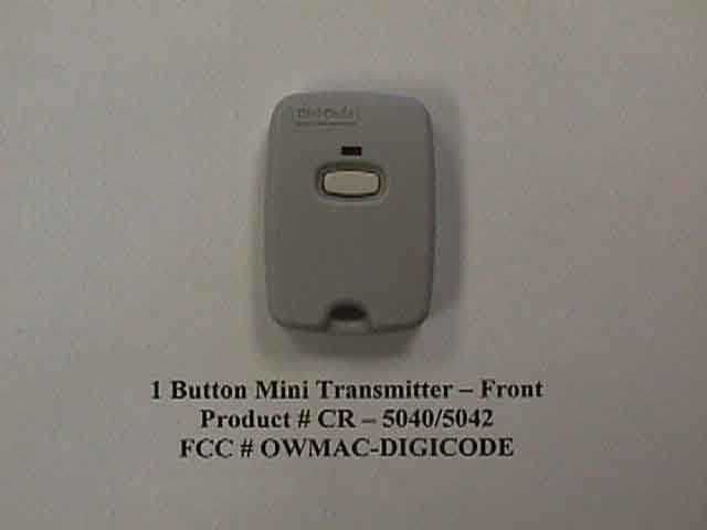
OWMAC-DIGICODE
Jun 26, 2000Security Transmitter
Equipment Class
DXX - Part 15 Low Power Communication Device Transmitter
OWMRC-DIGICODE
Jun 07, 2000Garage Door Remote Control
Equipment Class
DSC - Part 15 Security/Remote Control Transmitter
OWMHC-DIGICODE
Mar 20, 2000CRR - Superregenerative Receiver
Equipment Class
CRR - Superregenerative Receiver