OWMSC-DIGICODEGarage Door Opener/Security Device
Digi-Code Inc
Click to zoom
Application Details
- Equipment Class
- DSC - Part 15 Security/Remote Control Transmitter
- Date of Grant
- Jul 12, 2000
- Application Purpose
- Original Equipment
- Date of Application
- Jun 11, 2000
- Equipment Note
- Garage Door Opener/Security Device
- Frequency Range
- 310.00000000 - 310.00000000
- Company
- Digi-Code Inc
- Country
- United States
Documents & Files
Document Text
Text extracted from the exhibit documents filed with the FCC. Open a document above to read the original.
Users Manual
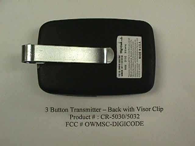
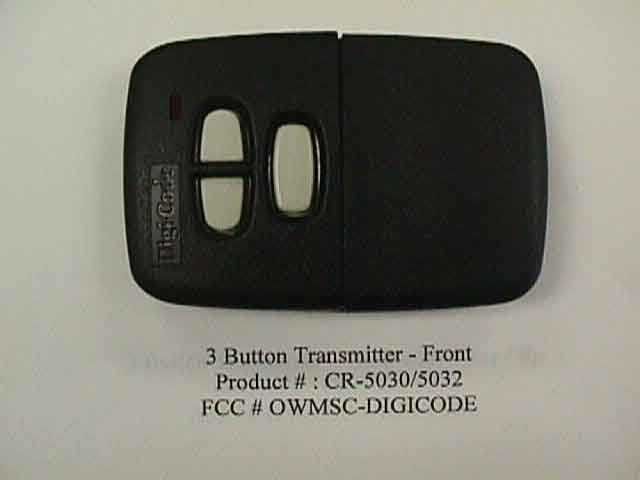
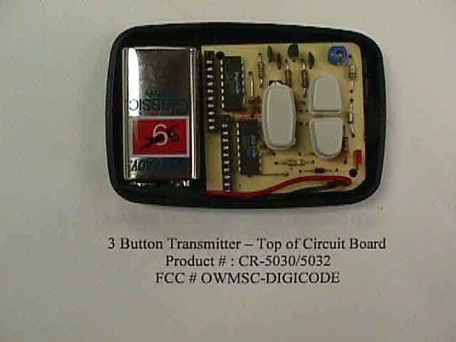
Installation Instructions Garage Door Opener Radio Controls Model 5030 (300 mHz) \ 5032 (310 mHz) Three Button Transmitters WARNING: • •• • Disconnect operator power before any installation or repair • •• • Always wear safety glasses Your Digi-Code radio controls are designed specifically to remotely control a garage door opener from within an automobile and to give years of trouble free service without adjustment. Because all radio controls are set with the even numbered switches in the “ON” position when they leave the factory, it is recommended that a different code be selected and set at the time of installation. Please refer to the “Setting the Code Switch” section for instructions. The radio frequency (RF) portion of the controls, however, are tuned to standard frequencies and are thoroughly tested at the factory. This permits the addition or replacement of either the transmitter or the receiver by specifying the Model number and the RF frequency designated on the identification label. RF adjustments are not needed nor should any be attempted. SECTION #1 SETTING THE CODE SWITCHES On the transmitter the entire front lower half of the case ( “ the battery hatch” ) is removeable. Use a coin or the curved end of the visor clip to disengage the lower half of the transmitter front. This will expose both the code switch and the battery compartment. ( SEE FIGURE #1 ) Figure #1 Once you have removed the battery hatch, locate the “CODE SWITCHES” above the battery. As shown above, the dual buttons are controlled by the right hand switch and the single button is controlled by the left hand switch. Before setting the receiver code switches, you will need to set the transmitter code switches on your model 5030 or 5032. We strongly suggest that you change the code from the factory setting to provide security for your own system, and to eliminate interference with neighboring systems. SETTING THE DUAL BUTTON CODE SWITCH Set code switch positions 1 through 9 to your personal code scheme ( THE 10 TH POSITION SWITCH MUST BE SET IN THE CLOSED POSITION “ON”), (Note: The switch is in the “on” position when it is depressed toward the number.) . We strongly urge that several coding schemes be avoided: ALL ON; 2,4,6,8,10, ON. These positions are similar to our or other manufacturers test positions, or are frequently used. SETTING RECEIVER #1 (WORKS WITH LEFT DUAL BUTTON ) Set your receiver code switch positions 1 through 9 to match the dual button code switch. Then make sure that the 10 th position switch on receiver #1 is set in the closed position “ON” . The left dual button on the transmitter should now operate this receiver. SETTING RECEIVER #2 (WORKS WITH RIGHT DUAL BUTTON ) Set the receiver code switch positions 1 through 9 to match the dual button code switch. Then make sure that the 10 th position switch on receiver #1 is set in the open position “OFF” . The right button on the transmitter should now operate this receiver. Once the codes have been set, check operation. SETTING THE SINGLE BUTTON CODE SWITCH Set code switch positions 1 through 10 to your personal code scheme, any combination of “on” or “off” positions can be selected (Note: The switch is in the “on” position when it is depressed toward the number.) . We strongly urge that several coding schemes be avoided: ALL ON; 2,4,6,8,10, ON. These positions are similar to our or other manufacturers test positions, or are frequently used. SETTING RECEIVER – TO WORK WITH SINGLE BUTTON Set the receiver code switches to match the code settings you entered for the single button switch in the transmitter, being sure both are set the same since a different setting of just one switch will prevent operation. Once the three codes have been set, check operation and reinsert the hatch. SECTION #2 SETTING THE TRANSMITTER CODE SWITCHES –TO WORK WITH EXISTING STANLEY GARAGE DOOR OPENERS. Set the transmitter using “ SETTING THE DUAL BUTTON CODE SWITCH” AND “SETTING THE SINGLE BUTTON CODE SWITCH” instructions from section #1 above. Set the first garage door opener using “ SETTING RECEIVER #1 (WORKS WITH LEFT DUAL BUTTON) “ instructions from section #1 above. Set the second garage door opener using “ SETTING RECEIVER #2 (WORKS WITH RIGHT DUAL BUTTON )” instructions from section #1 above. Set the third garage door opener using “ SETTING RECEIVER – TO WORK WITH SINGLE BUTTON ” instructions from section #1 above. SECTION #3 TRANSMITTER BATTERY REPLACEMENT The battery in the transmitter can be checked or changed by removing the front lower half of the transmitter. Use a coin or the curved end of the visor clip to disengage the lower half of the transmitter front. This will expose the battery compartment. Replacement battery must be a 9-volt. TO REPLACE OR ADD A SET A replacement or new transmitter or receiver may be purchased by specifying the Model Number and the RF frequency designated on the serial tag label. The RF frequency is set at the factory and must not be adjusted in the field. The digital code can be matched to the companion receiver or transmitter by following the “setting” procedures above. OPERATIONAL CHECK To check operation, move back about 50 feet and press the transmitter button. Operation should be reliable at this distance but environment and location of both the transmitter and receiver will effect the range. Try different mounting locations and positions in the vehicle. If operation is still undesirable, the problem may be isolated by: 1. Checking the door operator. If the door will not open when the wall button is pressed, the problem is likely to be the operator. If the door will open by pressing the wall button, but not when the radio control button is pressed, the problem is probably in the radios. 2. Replacing the transmitter battery. If, after performing the above operational checks, the controls still do not function, they should be returned to your dealer for repair or replacement. WARRANTY All Digi-Code door related products carry an e…
Text truncated - open the document above for the full version.
Operational Description
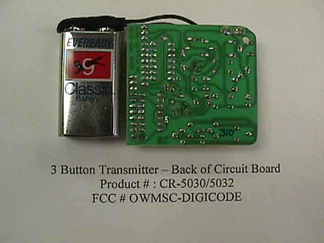
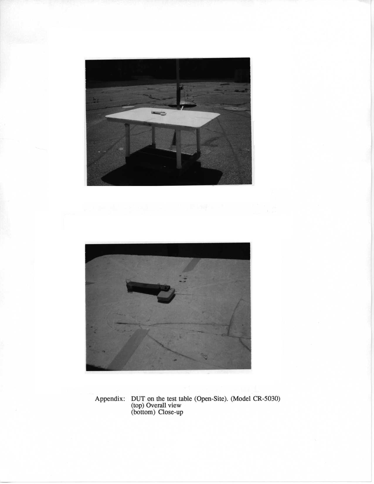
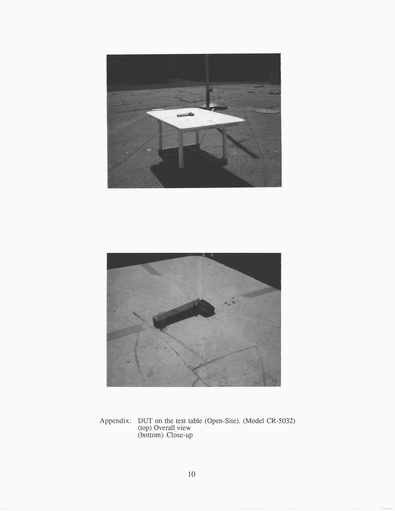
307 Robbins Dr. • Troy, Michigan 48083 • Tel: 248 589-3645 • Fax 248 588-6801 Description of Operation Model CR-5030 and Model CR-5032: These transmitters are all remote control devices designed and manufactured for the purpose of radio control of garage door openers and other like devices. The physical size of these devices is such that they can be either hand held or visor mounted on the interior of an automobile or similar vehicle. Model CR-5030 operates on a fixed frequency of 300 mHz and Model CR-5032 operates on a fixed frequency of 310 mHz. Operation or actuation of all of these devices is controled by a simple electromechanical switch. Depressing the switch causes the transmitter to emit the radio signal and upon releasing the switch, the transmitter ceases to emit the radio signal. Three button model provides the capability for activating three remote control receivers. Personal coding of each device is provided by a small 10 position switch which is mounted on the printed circuit board. Access to this switch is provided when the cover of the transmitter is removed. 10 switch positions provide 1,024 personal code selections. All models are compliant with F.C.C. Part 15 Rules.
Contact Information
Applicant
Richard J. Caceres(President)
Technical Contact
University of Michigan/EECSValdis V Liepa
[email protected]734-483-4211
1301 Beal AVE · Ann Arbor, Michigan · United States
Non-Technical Contact
University of Michigan/EECSValdis V Liepa
[email protected]734-483-4211
Technical Specifications
| # | Rule Parts | Frequency Range | Power Output |
|---|---|---|---|
| 2 | 15C | 310 MHz - 310 MHz | - |
Other Applications from Digi-Code Inc

OWM-ZD433
Jan 24, 2006Garage Door Opener
Equipment Class
DSR - Part 15 Remote Control/Security Device Transceiver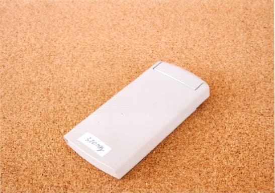
OWMCK-DIGICODE
Oct 08, 2001Security Remote Control
Equipment Class
DSC - Part 15 Security/Remote Control Transmitter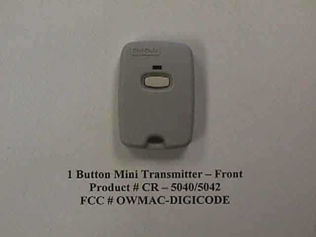
OWMAC-DIGICODE
Jun 26, 2000Security Transmitter
Equipment Class
DXX - Part 15 Low Power Communication Device Transmitter
OWMRC-DIGICODE
Jun 07, 2000Garage Door Remote Control
Equipment Class
DSC - Part 15 Security/Remote Control Transmitter
OWMHC-DIGICODE
Mar 20, 2000CRR - Superregenerative Receiver
Equipment Class
CRR - Superregenerative Receiver