OWWC230505SWideband Consumer Signal Booster
SHENZHEN HUAPTEC CO., LTD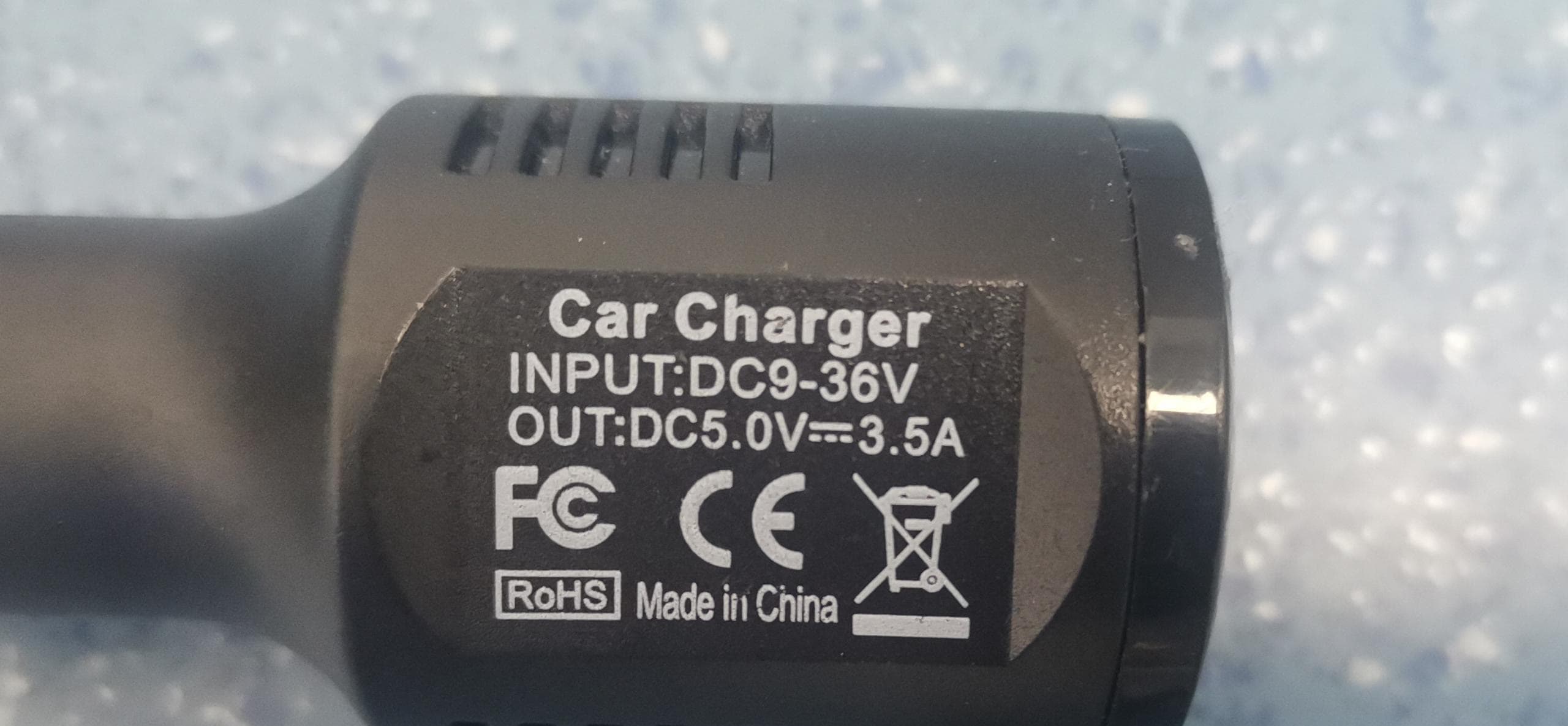
Click to zoom
Application Details
- Equipment Class
- DSS - Part 15 Spread Spectrum Transmitter
- Date of Grant
- May 15, 2023
- Application Purpose
- Original Equipment
- Date of Application
- May 15, 2023
- Equipment Note
- Wideband Consumer Signal Booster
- Frequency Range
- 2402.00000000 - 2480.00000000
- Company
- SHENZHEN HUAPTEC CO., LTD
- Country
- China
Documents & Files
Document Text
Text extracted from the exhibit documents filed with the FCC. Open a document above to read the original.
Users Manual
User Manual Travel 3.0 Car C30G-5S-BTW) Travel 3.0 RV C30G-5S-BTW.RV) Travel 3.0 Truck C30G-5S-BTW.TRUCK) Boost Your Bars and Keep You Connected to the World FOR VEHICLE (972) 870-5666 (M-F from 9 am - 5 pm CST) CONTENTS Introduction Pre-Installation Instructions LED Indicator Lights App Assisted Installation Troubleshooting Guide Technical Specifications FCC and IC Statements Return and Warranty Policies 04 04 05 11 12 23 24 25 28 Package Content Authorized Accessories List 01 Package Content 1 Booster Travel 3.0 Car Outside Magnetic Antenna Inside Panel AntennaDC Power Supply Other Accessories to fix the booster and antenna Package Content 2 BoosterOutside Omni-Directional Antenna Travel 3.0 RV Other Accessories Outside 26ft Cable Power Supply Inside Magnetic Antenna DC Power Supply to fix the booster and inside antenna 15.74in pole *2,Side-Exit Adapter,Spring, Mounting Accessories Package Content Note: Available accessories can be purchased through HiBoost.com 3 Booster Travel 3.0 Truck DC Power Supply Other Accessories Inside Panel Antenna to fix the booster and inside antenna Outside 15ft Cable Outside Omni-Directional Antenna 15.74in pole *2,Side-Exit Adapter,Spring, Mounting Accessories Warning: Un-authorized antennas, cables, and/or coupling devices are prohibited by new FCC rules, Please contact FCC for details: 1(888)-CALL-FCC. Authorized Accessories List Introduction Thanks again for purchasing HiBoost cell phone booster. The HiBoost vehicle series is a collection of precision-engineered products that improve cellular reception inside of vehicles by amplifying incoming and outgoing cell phone signals. HiBoost cell booster's exclusive cloud-based Signal Supervisor mobile application and LED indicator allows users to monitor the live status of HiBoost cell phone signal boosters directly from the LED indicator or remotely from a mobile device anywhere at any time. If there are any issues while installing a HiBoost cell phone signal booster, please contact the HiBoost technical support team through the following options Online Support: Create a ticket or chat via Signal Supervisor app (972) 870-5666 (M-F from 9am – 5 pm CST) [email protected] www.hiboost.com 4 Outside Antenna & Cable Kit Options Omni outside Antenna HPTOOC-0727-05SF1: 698-960MHz 2±0.5dBi/ 1710-2170MHz 2.5±0.5dBi /2300-2700MHz 3±0.5dBi Outside cable: Hiboost200/3D 26ft/8M; Hiboost200/3D 15ft/4.5M Outside Magnetic Antenna C-ANT-V02: 698-960MHz 1.5±0.5dBi/ 1700-2700MHz 2.5±0.5dBi Outside cable:3D-FB 13ft/4M Inside Antenna & Cable Kit Options Inside Panel Antenna C-ANT-FPC-V02: 698-960MHz 1±0.5dBi / 1700-2700MHz 2±0.5dBi Inside Magnetic Antenna C-ANT-V02: 698-960MHz 1.5±0.5dBi/ 1700-2700MHz 2.5±0.5dBi Inside cable: LMR100 9.8ft/3M; 3D-FB 13ft/4M Pre-Installation Instructions We strongly recommend you to read the user guide completely before installation. The vehicle booster provides app assisted installation, which is aunique method provided by HiBoost. 1.App Assisted Installation From Page 12~22. It's convenient and the best part is that the maximum booster gain can be reached. 5 The app helps you find the best installation For more precautions and details to install and use, please follow the Signal Supervisor app. Then why has HiBoost spent extra big efforts and costs to design app signal meter and LED light indicator to help you install? Out of many reasons, the most important one is that we would like you to get maximum gain from the vehicle booster, as it is most crucial for you to still get the signals even in quite remote areas, like in mountains or forests. As it is known and a big thanks, FCC makes signal boosters legal in 2014 so that every body can install and benefit from the signals; But FCC regulations do limit the gain and output power of all consumer boosters to low values in order to avoid any interference to the cell towers; Furthermore FCC stipulates that any improper install should trigger immediately further reduction of the booster’s already-limited gain and power to protect the towers. Therefore, you can understand how important you need to squeeze every last gain from the booster, even 1dB more power is so precious when you suffer from no signals. HiBoost app signal meter & LED light indicator will help you to fine tune the best power and get as much cover of your spaces. 6 7 General Working Principle: Please do spend sometime to read it fully, as it is crucial to get the best performance. Before we start any of the two ways, please allow us to spend 4 pages to make you understand how the vehicle booster system works for you. How HiBoost booster works Vice versa, inside antenna receives phone signal and sends to the booster, The booster then amplifies and sends it to outside antenna, Outside antenna sends signal to the cell tower. Then you can make phone calls and do internet streaming. Travel 3.0 Car 1.Outside antenna receives signal from nearby cell tower and sends it to the booster 2.The booster amplifies the signal and sends it to inside antenna 3.Inside antenna broadcasts it in the vehicle Outside Antenna Inside Antenna Power Supply Booster Travel 3.0 RV Travel 3.0 Truck 8 Outside Antenna Inside Antenna Booster Power Supply 2.The booster amplifies and sends it to inside antenna 3.Inside antenna broadcasts it in the vehicle 1.Outside antenna receives signal from nearby cell tower and sends it to the booster Outside Antenna Inside Antenna Power Supply Booster 2.The booster amplifies and sends it to inside antenna 3.Inside antenna broadcasts it in the vehicle 1.Outside antenna receives signal from nearby cell tower and sends it to the booster 9 Working Principle in Formula Outside Signal Outside Antenna Gain Outside Cable Loss Booster Gain Inside Cable Loss Inside Antenna Gain System Output Power Out of the Formula: Outside Signal: To be received by outside antenna from cell tower Outside Antenna Gain: The gain of the outside antenna Outside Cable Loss: The loss of the outside cable Booste…
Text truncated - open the document above for the full version.
External Photos
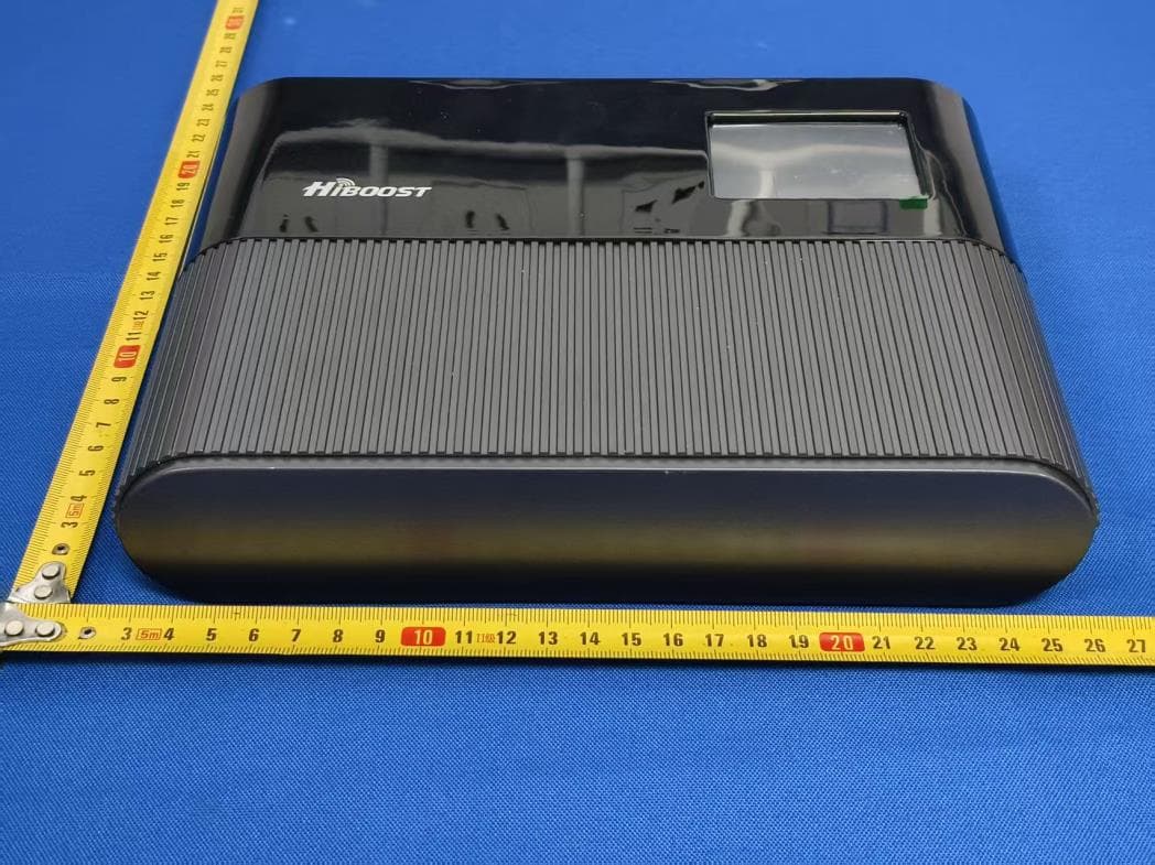
Shenzhen Accurate Technology Co., Ltd. FCC ID: OWWC230505S External Photos Page 1 of 10 External Photos Shenzhen Accurate Technology Co., Ltd. FCC ID: OWWC230505S External Photos Page 2 of 10 Shenzhen Accurate Technology Co., Ltd. FCC ID: OWWC230505S External Photos Page 3 of 10 Shenzhen Accurate Technology Co., Ltd. FCC ID: OWWC230505S External Photos Page 4 of 10 Shenzhen Accurate Technology Co., Ltd. FCC ID: OWWC230505S External Photos Page 5 of 10 Omni antenna (model: HPTOOC-0727-05SF1 ANT) Shenzhen Accurate Technology Co., Ltd. FCC ID: OWWC230505S External Photos Page 6 of 10 Magnetic antenna (model: C-ANT-V02 ANT) Shenzhen Accurate Technology Co., Ltd. FCC ID: OWWC230505S External Photos Page 7 of 10 Panel antenna( model: C-ANT-FPC-V02A ANT) Shenzhen Accurate Technology Co., Ltd. FCC ID: OWWC230505S External Photos Page 8 of 10 Shenzhen Accurate Technology Co., Ltd. FCC ID: OWWC230505S External Photos Page 9 of 10 Shenzhen Accurate Technology Co., Ltd. FCC ID: OWWC230505S External Photos Page 10 of 10 Car Charger
ID Label/Location Info
Shenzhen Accurate Technology Co., Ltd. Project No.: RA221229-64261E-RF LABEL AND LOCATION Page 1 of 3 Model: C30G-5S-BTW FCC ID Label FCC ID Label Location Information The label shown shall be permanently affixed at a conspicuous location on the device and be readily visible to the user at the time purchase (Labeling requirements per 2.925) Shenzhen Accurate Technology Co., Ltd. Project No.: RA221229-64261E-RF LABEL AND LOCATION Page 2 of 3 Model: C30G-5S-BTW.RV FCC ID Label FCC ID Label Location Information The label shown shall be permanently affixed at a conspicuous location on the device and be readily visible to the user at the time purchase (Labeling requirements per 2.925) Shenzhen Accurate Technology Co., Ltd. Project No.: RA221229-64261E-RF LABEL AND LOCATION Page 3 of 3 Model: C30G-5S-BTW.TRUCK FCC ID Label FCC ID Label Location Information The label shown shall be permanently affixed at a conspicuous location on the device and be readily visible to the user at the time purchase (Labeling requirements per 2.925)
Internal Photos
Shenzhen Accurate Technology Co., Ltd. FCC ID: OWWC230505S Internal Photos Page 1 of 11 Internal photos Shenzhen Accurate Technology Co., Ltd. FCC ID: OWWC230505S Internal Photos Page 2 of 11 Shenzhen Accurate Technology Co., Ltd. FCC ID: OWWC230505S Internal Photos Page 3 of 11 Shenzhen Accurate Technology Co., Ltd. FCC ID: OWWC230505S Internal Photos Page 4 of 11 Shenzhen Accurate Technology Co., Ltd. FCC ID: OWWC230505S Internal Photos Page 5 of 11 Shenzhen Accurate Technology Co., Ltd. FCC ID: OWWC230505S Internal Photos Page 6 of 11 Shenzhen Accurate Technology Co., Ltd. FCC ID: OWWC230505S Internal Photos Page 7 of 11 Shenzhen Accurate Technology Co., Ltd. FCC ID: OWWC230505S Internal Photos Page 8 of 11 Shenzhen Accurate Technology Co., Ltd. FCC ID: OWWC230505S Internal Photos Page 9 of 11 Shenzhen Accurate Technology Co., Ltd. FCC ID: OWWC230505S Internal Photos Page 10 of 11 Inside&BT/wifi antenna port Shenzhen Accurate Technology Co., Ltd. FCC ID: OWWC230505S Internal Photos Page 11 of 11 Outside antenna port
RF Exposure Info
Shenzhen Accurate Technology Co., Ltd Report No.: RA221229-64261E-RF-00 FCC Part 20.21 Page 1 of 2 FCC §1.1307 (b) (3) & §2.1091 –RF EXPOSURE Applicable Standard According to subpart 2.1091 systems operating under the provisions of this section shall be operated in a manner that ensures the public is not exposed to RF energy level in excess of the communication guidelines. According to KDB 447498 D04 Interim General RF Exposure Guidance SAR-Based Exemption: SAR-based thresholds are derived based on frequency, power, and separation distance of the RF source. The formula defines the thresholds in general for either available maximum timeaveraged power or maximum time-averaged ERP, whichever is greater. Per § 1.1307(b)(3)(i)(B), for single RF sources (i.e., any single fixed RF source, mobile device, or portable device, as defined in paragraph (b)(2) of this section): A single RF source is exempt if: the available maximum time-averaged power or effective radiated power (ERP), whichever is greater, is less than or equal to the threshold P th (mW) described in the following formula. This method shall only be used at separation distances (cm) from 0.5 centimeters to 40 centimeters and at frequencies from 0.3 GHz to 6 GHz (inclusive). P th is given by: For multiple RF sources: Multiple RF sources are exempt if: in the case of fixed RF sources operating in the same time-averaging period, or of multiple mobile or portable RF sources within a device operating in the same time averaging period, if the sum of the fractional contributions to the applicable thresholds is less than or equal to 1 as indicated in the following equation: Shenzhen Accurate Technology Co., Ltd Report No.: RA221229-64261E-RF-00 FCC Part 20.21 Page 2 of 2 MPE Results Tune-Up Power Including Tolerance: Mode Frequency (MHz) Tune up conducted power Antenna GainERP Evaluation Distance (m) Pth (mW) (dBm) (mW) (dBi)(dBd)(dBm)(mW) UL 698-716 25.0 316.23 2.0 -0.15 24.85 305.49 0.2 1424 776-787 24.0 251.19 2.0 -0.15 23.85 242.66 0.2 1583 824-849 25.0 316.23 2.0 -0.15 24.85 305.49 0.2 1681 1710-1755 21.0 125.89 3.0 0.85 21.85 153.11 0.2 3060 1850-1915 22.0 158.49 3.0 0.85 22.85 192.75 0.2 3060 DL 728-746 2.0 1.58 2.0 -0.15 1.85 1.53 0.2 1485 746-757 1.0 1.26 2.0 -0.15 0.85 1.22 0.2 1522 869-894 2.0 1.58 2.0 -0.15 1.85 1.53 0.2 1773 2110-2155 2.0 1.58 3.0 0.85 2.85 1.93 0.2 3060 1930-1995 2.0 1.58 3.0 0.85 2.85 1.93 0.2 3060 BT 2402-2480 10.5 11.22 3.0 0.85 11.35 13.65 0.2 3060 BLE 2402-2480 2.0 1.58 3.0 0.85 2.85 1.93 0.2 3060 Wi-Fi 2412-2462 14.5 28.18 3.0 0.85 15.35 34.28 0.2 3060 Note: The BT/BLE/Wi-Fi cannot transmit at same time The BT or BLE or Wi-Fi can transmit at same time with booster Simultaneously transmit consideration, the worst case: The ratio= P Booster /Pth Booster + P Wi-Fi / Pth Wi-Fi =316.23/1424+34.28/3060=0.233<1.0 The ERP was calculated base on the maximum value of antenna gain and cable loss combination. To maintain compliance with the FCC’s RF exposure guidelines, place the equipment at least 20cm from nearby persons. Result: Pass
Test Report
TEST REPORT Applicant: SHENZHEN HUAPTEC CO., LTD Address: 3rd FL,E BLDG, Sogood Science Park, SanWei community, Hangcheng Street, Bao'an District, Shenzhen, China FCC ID: OWWC230505S Product Name: Wideband Consumer Signal Booster Standard(s): 47 CFR Part 15, Subpart C(15.247) ANSI C63.10-2013 KDB 558074 D01 15.247 Meas Guidance v05r02 The above equipment has been tested and found compliant with the requirement of the relative standards by China Certification ICT Co., Ltd (Dongguan) Report Number: CR230209095-00E Date Of Issue: 2023/5/15 Reviewed By: Sun Zhong Title: Manager Test Laboratory: China Certification ICT Co., Ltd (Dongguan) No. 113, Pingkang Road, Dalang Town, Dongguan, Guangdong, China Tel: +86-769-82016888 China Certification ICT Co., Ltd (Dongguan) Report No.: CR230209095-00E Page 2 of 62 Test Facility The Test site used by China Certification ICT Co., Ltd (Dongguan) to collect test data is located on the No. 113, Pingkang Road, Dalang Town, Dongguan, Guangdong, China. The lab has been recognized as the FCC accredited lab under the KDB 974614 D01 and is listed in the FCC Public Access Link (PAL) database, FCC Registration No. : 442868, the FCC Designation No. : CN1314. The lab has been recognized by Innovation, Science and Economic Development Canada to test to Canadian radio equipment requirements, the CAB identifier: CN0123. Declarations China Certification ICT Co., Ltd (Dongguan) is not responsible for the authenticity of any test data provided by the applicant. Data included from the applicant that may affect test results are marked with a triangle symbol “▲”. Customer model name, addresses, names, trademarks etc. are not considered data. Unless otherwise stated the results shown in this test report refer only to the sample(s) tested. This report cannot be reproduced except in full, without prior written approval of the Company. This report is valid only with a valid digital signature. The digital signature may be available only under the Adobe software above version 7.0. This report may contain data that are not covered by the accreditation scope and shall be marked with an asterisk “★”. China Certification ICT Co., Ltd (Dongguan) Report No.: CR230209095-00E Page 3 of 62 CONTENTS T EST FACILITY .......................................................................................................................................... 2 DECLARATIONS .......................................................................................................................................... 2 DOCUMENT REVISION HISTORY .......................................................................................... 5 1. GENERAL INFORMATION .................................................................................................... 6 1.1 PRODUCT DESCRIPTION FOR EQUIPMENT UNDER TEST (EUT) ....................................................... 6 1.2 DESCRIPTION OF TEST CONFIGURATION ........................................................................................... 8 1.2.1 EUT Operation Condition: ............................................................................................................................. 8 1.2.2 Support Equipment List and Details .............................................................................................................. 8 1.2.3 Support Cable List and Details ...................................................................................................................... 8 1.2.4 Block Diagram of Test Setup ......................................................................................................................... 9 1.3 MEASUREMENT UNCERTAINTY ........................................................................................................ 11 2. SUMMARY OF TEST RESULTS .......................................................................................... 12 3. REQUIREMENTS AND TEST PROCEDURES .................................................................. 13 3.1 AC LINE CONDUCTED EMISSIONS .................................................................................................... 13 3.1.1 Applicable Standard ..................................................................................................................................... 13 3.1.2 EUT Setup.................................................................................................................................................... 14 3.1.3 EMI Test Receiver Setup ............................................................................................................................. 14 3.1.4 Test Procedure ............................................................................................................................................. 15 3.1.5 Corrected Amplitude & Margin Calculation ................................................................................................ 15 3.2 RADIATED SPURIOUS EMISSIONS ...................................................................................................... 16 3.2.1 Applicable Standard ..................................................................................................................................... 16 3.2.2 EUT Setup.................................................................................................................................................... 16 3.2.3 EMI Test Receiver & Spectrum Analyzer Setup ......................................................................................... 17 3.2.4 Test Procedure ............................................................................................................................................. 17 3.2.5 Corrected Amplitude & Margin Calculation ................................................................................................ 17 3.3 20 DB EMISSION BANDWIDTH ................................................................................…
Text truncated - open the document above for the full version.
Test Report
Inside Panel Antenna SPECIFICATION Model C-ANT-FPC-V02 I Electrical specifications I Frequency range (MHz) 698-960/1710-2700 Band width (MHz) 262/990 Gam(dBi) 1士05/2士05 Polarization Vertical Rad1at1on d1rect1on Omni Impedance (0) 50 VSWR <20 Maximum input power(W) 50 Lightning protection DC Ground I Mechanical specifications I Connector Cable Dimension(mm) Antenna weight(g) operating temperature Installs way RP-SMA 3 D-FB, Black, 3m 91*53*19 ;c::55 -40 ° C to+ 70 ° C Stick Radiation Patterns E-Plane ______________________________________________________________________________________ Manufacturer: SHENZHEN HUAPTEC CO.LTD Address: 3rd FL,E BLDG, Sogood Science Park, SanWei community Hangcheng Street, Bao'an District, Shenzhen,China Tel: 86-755-29921615 Email: [email protected]
Test Setup Photos
EXHIBIT D - TEST SETUP PHOTOGRAPHS Conducted Emissions Front View Adapter Power Conducted Emissions Side View Adapter Power Radiated Emission Above 1GHz View – Adapter Power Radiated Emission Above 1GHz View – DC Power Radiated Emission Above 1GHz View - Adapter Power
Contact Information
Applicant
Yanwei Wang
Test Firm
CHINA CERTIFICATION ICT CO., LTD (DONGGUAN)Tanie Ou
[email protected]0086 0769 86858888
Technical Specifications
| # | Rule Parts | Frequency Range | Power Output |
|---|---|---|---|
| 1 | 15C | 2.40 GHz - 2.48 GHz | 11.00 mW |
Other Applications from SHENZHEN HUAPTEC CO., LTD
OWWF1151725S
Jul 20, 2026Signal Booster
Equipment Class
B2W - Part 20 Wideband Consumer Booster (CMRS)
OWWF110655S
Jul 01, 2024Zorida Ace 3S
Equipment Class
B2W - Part 20 Wideband Consumer Booster (CMRS)
OWWF110725S
Jun 27, 2024Zorida Ace 5S
Equipment Class
B2W - Part 20 Wideband Consumer Booster (CMRS)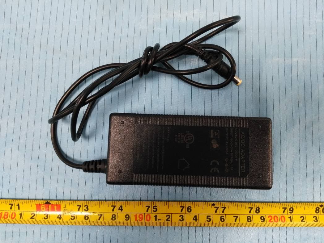
OWWF108555S
Jan 07, 2021Hiboost Signal Booster
Equipment Class
B2W - Part 20 Wideband Consumer Booster (CMRS)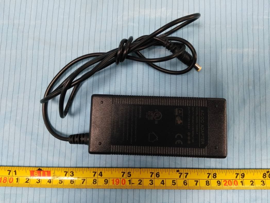
OWWF115705S
Jan 05, 2021Hiboost Signal Booster
Equipment Class
B2W - Part 20 Wideband Consumer Booster (CMRS)