OWWF115705SHiboost Signal Booster
SHENZHEN HUAPTEC CO., LTD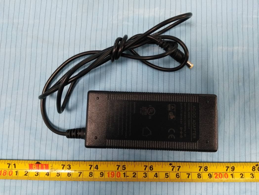
Click to zoom
Application Details
- Equipment Class
- B2W - Part 20 Wideband Consumer Booster (CMRS)
- Date of Grant
- Jan 05, 2021
- Application Purpose
- Original Equipment
- Date of Application
- Jan 05, 2021
- Equipment Note
- Hiboost Signal Booster
- Frequency Range
- 746.00000000 - 757.00000000
- Company
- SHENZHEN HUAPTEC CO., LTD
- Country
- China
Documents & Files
Document Text
Text extracted from the exhibit documents filed with the FCC. Open a document above to read the original.
Users Manual
Boost Your Bars User Manual F20GI-5S-IoT F20G-5S-IoT Mobile Signal Booster WHAT'S INCLUDED HOW IT WORKS HOW TO INSTALL YOUR SIGNAL BOOSTER 1.1 Overview 1.2 Booster System Installation Examples 1.3 Installation Preparation 1.4 How to find the location with the strongest received signal 1.5 Install Outdoor Antenna 1.6 Install Indoor Antenna 1.7 Install Signal Booster 1.8 Run coaxial cable 1.9 Power up your the Signal Booster SIGNAL BOOSTER STATUS Booster Ports'Description LCD Features LED Status Control Buttons Operation and Manual gain control (MGC) TROUBLESHOOTING AUTHORIZED KITTING OPTIONS FCC RF EXPOSURE STATEMENT IC RF EXPOSURE STATEMENT WARNING AND STATEMENT SPECIFICATION PRODUCT WARRANTY 3 4 4 4 4 5 6 8 8 9 9 10 10 11 11 13 14 15 16 17 17 17 19 20 CONTENT 2/20 3/20 HOW IT WORKS The HiBoost Home Plus signal booster is designed to help mobile users improve signal in homes, offices, and other areas where cellular signal is weak or unreliable. The outdoor antenna receives the signal from the nearest cellular tower, amplifies it, and transmits to the signal booster. Then the indoor antenna will receive the signal and retransmit it to your mobile device. The signals produced by your phone are also amplified by the indoor antenna via the booster and outdoor antenna. This manual provides simple installation instructions that will have your signal booster kit running in record time. HOW TO INSTALL YOUR SIGNAL BOOSTER 1.1 Overview This manual will help you properly install your signal booster kit. It is important to read through all of the installation steps before installing your equipment. Thoroughly read through the instructions, visualize where all the equipment will need to be installed and do a soft installation by placing the devices where they need to be before mounting any equipment. 1.2 Booster System Installation Examples 1-Outdoor wide band Directional antenna 2-50ft (15.2m) Hiboost200 low-loss cable 3-Home Plus with-in antenna 4/20 1-Outdoor wide band Directional antenna 2-50ft (15.2m) Hiboost200 low-loss cable 3- You can add an indoor panel/omni antenna and 50ft (15.2m) Hiboost200 low-loss cable to extend the coverage 1- 0utdoor Wide Band Directional Antenna 2- 50ft (15.2m) Hiboost200 Low-loss Cable 3- You can add an indoor panel/omni antenna with SMA-N connector to connect 50ft (15.2m) Hiboost200 low-loss cable to extend the coverage (built-in antenna will be automatically disabled) 1.3 Installation Preparation Before you install • Make sure you have sufficient cable length between the proposed outdoor/indoor antenna location and booster connector. • Make sure the position you install the booster is near to an existing electrical outlet, well ventilated, and away from excessive heat, moisture, and direct sunlight. 5/20 Before you get started, you will need to plan the layout of your system. This involves finding the location with the strongest received signal from the cellular tower, as well as antenna, booster, and cable placement. General installation steps: 1. Find the strongest received signal for the location of the outdoor antenna. 2. Install the outdoor antenna on the roof to obtain the strongest downlink signal from the local cellular towers. It should also be as far away as possible from where you plan to place the indoor antenna (vertical separation is more important than horizontal separation). 3. Install the indoor antennas where you want to improve the signal level. 4. Mount the booster, connect the cables from the outdoor antenna and indoor antenna at the designated ports, and connect the booster to the AC supply (make sure all the cables are connected before applying power). 1.4 How to find the location with the strongest received signal The outdoor signal strength the booster receives directly affects the efficiency of the indoor coverage. That is why it is crucially important to install the antenna at a good location and point it properly towards a tower where signal reception is the strongest. There are many methods that can be used to find the strongest signal from the cellular towers. One is to use the LCD display on the booster that shows the downlink power output of the booster in each band, the other is to use a mobile phone or mobile phone app to test signal strength, and the third is to use a commercially available signal strength meter. We highly recommend that you use the LCD display on the booster as this method is generally more convenient. However, in situations where the desired carrier's signal is much weaker than the other local signals, using a mobile phone, app, or signal level meter can be a more accurate method of homing in on the best signal for installation. • LCD Display Method Connect the outdoor antenna to the booster's outdoor port. Fix the outdoor Tools Required Phillips ScrewdriverDrillMobile Phone 6/20 antenna on the roof of the building and point it to the nearest cell tower. Then have a look at the gain and output power value displayed on the booster's LCD. Note: Above values displayed on the LCD are examples for Home 10K Plus, other models please refer to the data sheet. The outdoor antenna receives the strongest signal when the booster's downlink output power reaches its highest level in each band. If the LCD shows maximum gain and power, and there are not any alarms (no ISO, ALC, OFF legend flashing and no quick flashing green or red in LEDs), it means the present location is the best for ensuring that the booster has maximized performance. Note: These showed values may vary dynamically at times between 1-3 dB which is normal due to outdoor signal conditions. • Mobile Phone Method You can use a mobile phone to test signal strength on the top of the building. The number of bars on the network indicator will define approximate strength of the received signal. Normally the roof of the building is the best place to receive the strongest signal. As shown on the drawing below, you need to test the signal in the points from A to E, an…
Text truncated - open the document above for the full version.
Attestation Statements
SHENZHEN HUAPTEC CO., LTD Address: 3rd FL,E BLDG,Sogood Science Park,SanWei community, Hangcheng Street,Bao'anDistrict,Shenzhen,China, Tel.: 86-755-29921615 Fax: 86-755-29921165 E-mail: [email protected] Date: 2020-11-23 Attestation Letter To: FEDERAL COMMUNICATIONS COMMISSIONS Authorization and Evaluation Division 7435 Oakland Mills Road Columbia, MD 21046 Dear Sir or Madam: We, SHENZHEN HUAPTEC CO., LTD, hereby declare that the certified Hiboost Signal Booster under FCC ID: OWWF115705S, Model number: F20GI-5S-IoT, F15G-5S-IoT, F10G-5S-IoT, F20G-5S-IoT, F15GI-5S-IoT , F10GI-5S-IoT whi ch is manufactured and test to ensure FCC compliance: (1) Licensee consent for provider-specific booster has been obtained (consent be made available upon FCC/TCB request) (2) NPS and other compliance/safeguard features have been implemented (3) NPS and other compliance/safeguard features are defaulted to “ON” configuration (in operation) (4) NPS and other compliance/safeguard features cannot be field reconfigured, disabled or removed (5) Consumer booster is not user programmable, does not need fine tuning or adjustment, does not require professional installation (6) Future software upgrade will not cause non-compliance Sincerely Yours, Signature: Yanwei Wang Manager
Cover Letter(s)
QA-FR-170-B SHENZHEN HUAPTEC CO., LTD Address: 3rd FL, E BLDG, Sogood Science Park, SanWei community, Hangcheng Street, Bao'an District, Shenzhen, China Email: [email protected] Tel: 86-755-29921615 Fax: 86-755-29921165 FCC Authorization 2020-09-21 FEDERAL COMMUNICATIONS COMMISSIONS Authorization and Evaluation Division 7435 Oakland Mills Road Columbia, MD 21046 Subject: Agent Authorization To whom it may concern: We (SHENZHEN HUAPTEC CO., LTD), the undersigned, hereby authorize Bay Area Compliance Laboratories Corporation to act on its behalf in all matters relating to application for Equipment authorization, including the signing of all documents relating to these matters. All acts carried out by Bay Area Compliance Laboratory Corporation on our behalf shall have the same effect as our own action. We, the undersigned, hereby certify that we are not subject to a denial of federal benefits, that includes FCC benefits, pursuant to Section 5301 of the Anti-Drug Abuse Act of 1988, 21 U.S.C. 862. This authorization is valid until further written notice from the applicant. Sincerely, Signature: Yanwei Wang Title: Manager
Cover Letter(s)
SHENZHEN HUAPTEC CO., LTD Address: 3rd FL, E BLDG, Sogood Science Park, SanWei community, Hangcheng Street, Bao'an District, Shenzhen, China Email: [email protected] Tel: 86-0755-29921615 Fax: 86-0755-29921165 FCC Confidential Authorization 2020-09-21 FEDERAL COMMUNICATIONS COMMISSIONS Authorization and Evaluation Division 7435 Oakland Mills Road Columbia, MD 21046 Subject: Confidentiality Request regarding application for certification of FCC ID: OWWF115705S In accordance with Sections 0.457 and 0.459 of the Commission’s Rules, (SHENZHEN HUAPTEC CO., LTD) hereby requests long-term confidential treatment of information accompanying this application as outlined below: Block Diagram Schematics Operation Description Parts List/Tune up procedure (for licensed devices) The above materials contain proprietary and confidential information not customarily released to the public. The public disclosure of these materials provides unjustified benefits to its competitors in the market. Sincerely, Signature: Yanwei Wang Title: Manager
Cover Letter(s)
SHENZHEN HUAPTEC CO., LTD Address: 3rd FL, E BLDG, Sogood Science Park, SanWei community, Hangcheng Street, Bao'an District, Shenzhen, China Tel: 86-755-29921615 Email: [email protected] Product Similarity Declaration Date: 2020-12-25 To: FEDERAL COMMUNICATIONS COMMISSIONS Authorization and Evaluation Division 7435 Oakland Mills Road Columbia, MD 21046 Dear Sir/Madam, We, SHENZHEN HUAPTEC CO., LTD, hereby declare that we have a product named as Hiboost Signal Booster, (model: F20GI-5S-IoT, FCC ID: OWWF115705S) was tested by BACL, Meanwhile, for our marketing purpose, we would like to list a series model (F15G-5S-IoT, F10G-5S-IoT, F20G-5S-IoT, F15GI-5S-IoT, F10GI-5S-IoT) on reports and certificate, all the models are identical in schematics, they have different model name and different antenna gain and power . No other changes are made on them. Model Gain(UL/DL) Power(UL/DL) Implementation mode F20GI-5S-IoT 66dB/70dB 21dBm/14dBm Different outputs can be achieved through software settings F15GI-5S-IoT 63dB/68dB 20dBm/12dBm F10GI-5S-IoT 60dB/65dB 20dBm/10dBm F20G-5S-IoT 66dB/70dB 20dBm/13dBm F15G-5S-IoT 63dB/68dB 20dBm/12dBm F10G-5S-IoT 60dB/65dB 20dBm/10dBm We confirm that all information above is true, and we’ll be responsible for all the consequences. Please contact me if you have any question. Sincerely, Signature: Yanwei Wang Title:Manager
External Photos
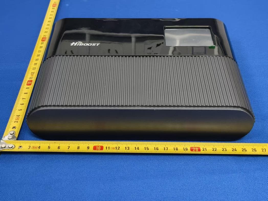
Bay Area Compliance Laboratories Corp. (Shenzhen) Project No.: RSZ200831003 Page 1 of 5 EXHIBIT B - EUT EXTERNAL PHOTOGRAPHS Bay Area Compliance Laboratories Corp. (Shenzhen) Project No.: RSZ200831003 Page 2 of 5 Bay Area Compliance Laboratories Corp. (Shenzhen) Project No.: RSZ200831003 Page 3 of 5 Bay Area Compliance Laboratories Corp. (Shenzhen) Project No.: RSZ200831003 Page 4 of 5 Power Cable Bay Area Compliance Laboratories Corp. (Shenzhen) Project No.: RSZ200831003 Page 5 of 5 Adapter
Internal Photos
Bay Area Compliance Laboratories Corp. (Shenzhen) Project No.: RSZ200831003 Page 1 of 4 EXHIBIT C - EUT INTERNAL PHOTOGRAPHS Bay Area Compliance Laboratories Corp. (Shenzhen) Project No.: RSZ200831003 Page 2 of 4 Bay Area Compliance Laboratories Corp. (Shenzhen) Project No.: RSZ200831003 Page 3 of 4 Bay Area Compliance Laboratories Corp. (Shenzhen) Project No.: RSZ200831003 Page 4 of 4 Internal Antenna Bluetooth & Wi-Fi Module (FCC ID: 2AC7Z-ESP32WROVERB)
RF Exposure Info
Bay Area Compliance Laboratories Corp. (Shenzhen) Report No.: RSZ200831003-00 FCC Part 20.21 Page 1 of 2 FCC §1.1307 (b) (1) & §2.1091 –MAXIMUM PERMISSIBLE EXPOSURE (MPE) Applicable Standard According to subpart 1.1307 (b)(1), 2.1091 systems operating under the provisions of this section shall be operated in a manner that ensures the public is not exposed to RF energy level in excess of the communication guidelines. Limits for General Population/Uncontrolled Exposure Limits for General Population/Uncontrolled Exposure Frequency Range (MHz) Electric Field Strength (V/m) Magnetic Field Strength (A/m) Power Density (mW/cm 2 ) Averaging Time (Minutes) 0.3-1.34 614 1.63 *(100) 30 1.34-30 824/f 2.19/f *(180/f 2 ) 30 30-300 27.5 0.073 0.2 30 300-1500 / / f/1500 30 1500-100,000 / / 1.0 30 f = frequency in MHz * = Plane-wave equivalent power density MPE Calculated : Predication of MPE limit at a given distance S = 2 4R PG π S = power density (in appropriate units, e.g. mW/cm2) P = power input to the antenna (in appropriate units, e.g., mW). G = power gain of the antenna in the direction of interest relative to an isotropic radiator, the power gain factor, is normally numeric gain. R = distance to the center of radiation of the antenna (appropriate units, e.g., cm) Bay Area Compliance Laboratories Corp. (Shenzhen) Report No.: RSZ200831003-00 FCC Part 20.21 Page 2 of 2 MPE Results Tune-Up Power Including Tolerance: Note: *The EUT contains a certified module (FCC ID: 2AC7Z-ESP32WROVERB) According to the MPE reports of FCC ID: 2AC7Z-ESP32WROVERB, Wi-Fi and Bluetooth can’t transmit simultaneously, so consider the Booster and Wi-Fi transmitting simultaneously is the worst case: The ratio= MPE/Limit Booster + MPE/Limit Wi-Fi =0.05/0.465+0.1182/1=0.2265<1.0 The maximum power density was calculated base on the maximum value of antenna gain and cable loss combination. To maintain compliance with the FCC’s RF exposure guidelines, place the equipment at least 20cm from nearby persons. Result: Pass Mode Frequency band (MHz) Antenna Gain Maximum Tune-up Power Cable Loss (dB) Evaluation Distance (cm) Power Density (mW/cm 2 ) MPE Limit (mW/cm 2 ) (dBi) (numeric)(dBm) Uplink 698-716 8 6.31 21 4.97 20 0.050 0.465 776-787 8 6.31 21 4.97 20 0.050 0.517 824-849 8 6.31 21 5.17 20 0.048 0.549 1710-1755 9 7.94 21 7.51 20 0.035 1.0 1850-1915 9 7.94 20 7.51 20 0.028 1.0 Downlink 728-746 5 3.16 14 4.97 20 0.005 0.485 746-757 5 3.16 11 4.97 20 0.003 0.497 869-894 0 1.00 14 0 20 0.005 0.579 2110-2155 0 1.00 14 0 20 0.005 1.0 1930-1995 0 1.00 14 0 20 0.005 1.0 Wi-Fi* 2412-2462 3.74 2.37 24 0 20 0.1182 1.0 BLE* 2402-2480 3.74 2.37 2 0 20 0.0007 1.0 BT* 2402-2480 3.74 2.37 5.5 0 20 0.0017 1.0
Test Report
Note: This report may contain data that are not covered by the A2LA accreditation and are marked with an asterisk “★”. BACL is not responsible for the authenticity of any test data provided by the applicant. Data included from the applicant that may affect test results are marked with an asterisk ’*’. Customer model name, addresses, names, trademarks etc. are not considered data. This report cannot be reproduced except in full, without prior written approval of the Company. Unless otherwise stated the results shown in this test report refer only to the sample(s) tested. This report is valid only with a valid digital signature. The digital signature may be available only under the Adobe software above version 7.0. FCC PART 20.21 TEST REPORT For SHENZHEN HUAPTEC CO., LTD 3rd FL, E BLDG, Sogood Science Park, SanWei community, Hangcheng Street, Bao’an District, Shenzhen, China FCC ID: OWWF115705S Report Type: Original Report Product Type: Hiboost Signal Booster Re port Number: RSZ200831003-00 Re port Date: 2020-10-21 Reviewed B y: Jimmy Xiao RF Engineer Prepared By: Bay Area Compliance Laboratories Corp. (Shenzhen) 6/F., West Wing, Third Phase of Wanli Industrial Building, Shihua Road, Futian Free Trade Zone, Shenzhen, Guangdong, China Tel: +86-755-33320018 Fax: +86-755-33320008 www.baclcorp.com.cn Bay Area Compliance Laboratories Corp. (Shenzhen) Report No.: RSZ200831003-00 FCC Part 20.21 Page 2 of 201 TABLE OF CONTENTS GENERAL INFORMATION ....................................................................................................................................... 4 PRODUCT DESCRIPTION FOR EQUIPMENT UNDER TEST (EUT) ..................................................................................... 4 OBJECTIVE ................................................................................................................................................................... 4 TEST METHODOLOGY .................................................................................................................................................. 4 MEASUREMENT UNCERTAINTY .................................................................................................................................... 5 TEST FACILITY ............................................................................................................................................................. 5 SYSTEM TEST CONFIGURATION .......................................................................................................................... 6 DESCRIPTION OF TEST CONFIGURATION ...................................................................................................................... 6 EUT EXERCISE SOFTWARE .......................................................................................................................................... 6 SPECIAL ACCESSORIES ................................................................................................................................................. 7 EQUIPMENT MODIFICATIONS ....................................................................................................................................... 7 SUPPORT EQUIPMENT LIST AND DETAILS .................................................................................................................... 7 EXTERNAL I/O CABLE .................................................................................................................................................. 7 BLOCK DIAGRAM OF TEST SETUP ................................................................................................................................ 7 SUMMARY OF TEST RESULTS ............................................................................................................................... 8 TEST EQUIPMENT LIST ........................................................................................................................................... 9 § 20.21(E)(3) – AUTHORIZED FREQUENCY BAND VERIFICATION ............................................................. 11 APPLICABLE STANDARD ............................................................................................................................................ 11 TEST PROCEDURE ...................................................................................................................................................... 11 TEST DATA ................................................................................................................................................................ 12 § 20.21(e)(8)(i)(D) ,§ 20.21(e)(8)(i)(B)& §20.21(e)(4)– MAXIMUM POWER MEASUREMENT ....................... 24 APPLICABLE STANDARD ............................................................................................................................................ 24 TEST PROCEDURE ...................................................................................................................................................... 24 TEST DATA ................................................................................................................................................................ 25 § 20.21(e)(8)(i)(C)(2), § 20.21(e)(8)(i)(B)&§20.21(e)(4) – MAXIMUM BOOSTER GAIN COMPUTATION .... 29 APPLICABLE STANDARDS........................................................................................................................................... 29 TEST PROCEDURE ...................................................................................................................................................... 29 TEST DATA ................................................................................................................................................................ 29 § 20.21(e)(8)(i)(F)- INTERMODULATION PRODUCT.......................................................................................... 32 APPL…
Text truncated - open the document above for the full version.
Contact Information
Applicant
Yanwei Wang
Test Firm
Bay Area Compliance Laboratories Corp. (Shenzhen)Well Wang
[email protected]+86 (0) 755 33320018
Technical Specifications
| # | Rule Parts | Frequency Range | Power Output | Emission | Tolerance |
|---|---|---|---|---|---|
| 38 | 27 | 746 MHz - 757 MHz | 10.00 mW | D7W | Amp |
Other Applications from SHENZHEN HUAPTEC CO., LTD
OWWF1151725S
Jul 20, 2026Signal Booster
Equipment Class
B2W - Part 20 Wideband Consumer Booster (CMRS)
OWWF110655S
Jul 01, 2024Zorida Ace 3S
Equipment Class
B2W - Part 20 Wideband Consumer Booster (CMRS)
OWWF110725S
Jun 27, 2024Zorida Ace 5S
Equipment Class
B2W - Part 20 Wideband Consumer Booster (CMRS)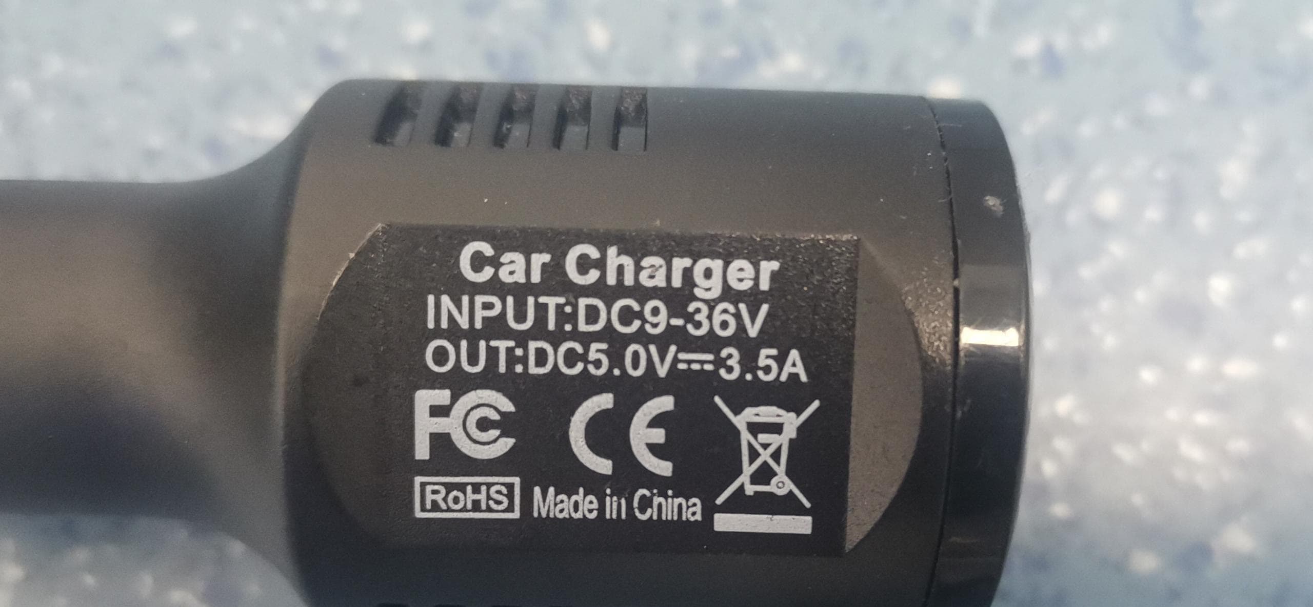
OWWC230505S
May 15, 2023Wideband Consumer Signal Booster
Equipment Class
DSS - Part 15 Spread Spectrum Transmitter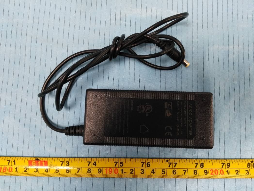
OWWF108555S
Jan 07, 2021Hiboost Signal Booster
Equipment Class
B2W - Part 20 Wideband Consumer Booster (CMRS)