OYE-MDTR303CONTROL ALARM TRANSMITTER
Miller Edge, Inc.
Click to zoom
Application Details
- Equipment Class
- DSC - Part 15 Security/Remote Control Transmitter
- Date of Grant
- Feb 06, 2012
- Application Purpose
- Original Equipment
- Date of Application
- Feb 06, 2012
- Equipment Note
- CONTROL ALARM TRANSMITTER
- Frequency Range
- 303.82500000 - 303.82500000
- Company
- Miller Edge, Inc.
- Country
- United States
Documents & Files
Document Text
Text extracted from the exhibit documents filed with the FCC. Open a document above to read the original.
Users Manual
Miller Edge, Inc. Monitored Device Radio ME-MDTR-10 303.825 MHz Transmitter FCC ID: OYE-MDTR303 TRADE NAME: Miller Edge MODEL: ME-MDTX-10 This device complies with Part 15 of the FCC Rules. Operation is subject to the following two conditions: (1) this device may not cause harmful interference, and (2) this device must accept any interference received, including interference that may cause undesired operation. Installation Instructions for Miller Edge Inc. Monitored Device Ping Radio ME-MDTX-10 and ME-MDRX-10 Kit Contents: 1. ME-MDTX-10 Transmitter Unit 2. (2) AA Lithium Batteries 3. ME-MDRX-10 Receiver Unit 4. Receiver Antenna Customer Supplied: 1. Terminated Edge (or Device) 2. Source of 12 to 24V AC or DC, @ 100mA, min. 1 Tools Required: 1. 3/32” Flat blade screwdriver 2. ¼” Flat blade screwdriver 3. #1 Philips Head screwdriver 4. Optional VOM for test purposes 5. Mounting screws (as required) Transmitter Test and Installation: Step 1. Open and unpack the transmitter and receiver unit. Unpack the antenna and batteries. Unpack the optional receiver wiring harness. 2 Step 2. Remove the Transmitter cover (using the ¼” Flat screw- driver) and place the cover to the left of the unit for reference. Step 3. Remove the Transmitter PCB from the enclosure using the #1 Philips screw driver on the 4 corner screws. Step 4. Route the cable from the monitored device (Edge) through the cable gland for approximately four inches. Strip 2” of sheathing from the cable end. Strip the insulation from the two wires back ½”. Twist the wires to tighten the strands and fold each back ¼”. See Fig. 1. 3 Step 5. Place the two AA Lithium batteries in their holders paying attention to their polarity. Note: A wrongly installed battery will not do harm to the unit but the transmitter will not operate, and the PCB will have to be removed to correct the error. Step 6. Tuck the wires connected to the SE terminal block neatly between the batteries and pull the excess wire back through the cable gland; re-seat the PCB and replace the 4 mounting screws. Tighten the cable gland. Step 7. Set the Termination Device switch to either 10K resistive, or 9.1V Diode. This selection must match the Safety Edge Termination type. 4 Step 8. Transmitter Quick Test: Set the Tx/Rx Group and Address switches to the desired positions. If the Group switch is set to 0, the address switch may be set to any position between 0 and F. If the Group switch is set to 1, the Address switch may be set to any position between 0 and B. The remaining positions, C, D, E, and F are reserved for factory testing. Momentarily press the TEST button to load the address and group data. 5 The Red and Green LEDs used to indicate Tx Data and Low Battery condition will flash momentarily during the power on sequence (when the batteries are installed). The Green Tx Data LED should flash. The Red Low Battery LED will only light when the batteries fall below 2.4v. Note: Low Battery data is also sent to the receiver and displayed there. Step. 9 Replace the cover on the Transmitter. Tighten the screws. Step 10. Mount the Transmitter on the bottom bar of the door. 6 The mounting holes are located under the cover mounting screws. The transmitter must be mounted with it’s top cover facing upward. Fig. 1 CONNECT SAFETY EDGE WIRES TO 'SE' K O SE 7 Receiver Installation and Test: Step 1. Remove the cover from the Receiver Unit (ME-MDRX-10) and place it alongside of the receiver. Step 2. Route the wires from the operator source (12 to 24v AC/DC) to the Power Terminal block on the receiver. The power input is polarity independent and accepts either AC or DC. Note: An external wall transformer may be used if 12 – 24 VAC/DC is not available from the operator unit. Step 3. Set the Rx Group and Address switches to match the transmitter switch settings. 8 Step 4 Connect the antenna to the receiver RF board. See Fig. 2. Step 5 The termination header has a jumper that can be pulled straight up and re-inserted into the proper position. Set the termination selection jumper to either 10K resistive or 9.1V Diode. See Fig.3. Step 6 Preliminary Test Check: Confirm that the Transmitter is ON, and power to the receiver is ON. (Confirm that the Blue LED Power light is On.) Activate the Safety Edge (or monitored device) and check that the Address Valid (Yellow LED) is ON. IF the Address Valid LED is not on, check that the Group and Address switches match the transmitter’s switch settings 9 Check that the Photo-Eye and Safety-Edge LEDs (red and green respectively) are lit. Clear the Edge (or safety device) and note that the Photo-eye and Safety Edge LEDs go OFF. Step 7. If the above tests pass, mount the receiver close to the operator and in the line-of-sight of the transmitter. Proceed to connect the receiver’s SE or PE output to the operator. Step 8. Operator - Safety Device Test: Confirm UL operator require- ments for momentary pressure operators. F i g . 2 10 Functional Door Test: Idle Indications, NO problems: Tx No lights ON Rx Only Blue LED (power) ON PRESS & HOLD the Safety Edge: Tx A brief blink of Green LED Rx A brief blink of Yellow LED Red (PhotoEye) LED ON Green (Safety Edge)LED ON and, after a second, Red (Ping Loss) LED comes ON RELEASE the safety Edge: Tx A brief blink of Green LED Rx A brief blink of Yellow LED Red (PhotoEye) LED is OFF Green (SafetyEdge) LED is OFF and, after 1-2 seconds, Red (PingLoss) LED is OFF 11 Preliminary Specifications: RF Frequency 303.825 MHz Modulation OOK Data Rate 19.2Kbps Discrete addresses 28 Tx to Rx Range 3’ – 100’ Enclosure polycarbonate Transmitter: Tx Battery Li/FeS 2 (Energizer L91, 2- AA cells) Avg. Battery Life, 23°C: 12 Months Operating Voltage: 2.2V to 3.6V Operating Temp.: -40°F to 140°F Operating Humidity: 0 to 100% 12 Mounting: 4 - #6 self-tap screws Size: 5 5/8” x 1 ¾” x 1 ¾” Antenna: Integral helical ¼ λ Indicators: (2) low battery/test mode (Red) transmission ON (Green) Input Connections: Safety Edge sensor, 2 wire; w/switch selectab…
Text truncated - open the document above for the full version.
External Photos
Retlif Testing Laboratories, Test Report R-1771P-3, Miller Edge FCC ID: OYE-MDTR303 Page 1 of 4 External Photographs Miller Edge, FCC ID: OYE-MDTR303 Retlif Testing Laboratories, Test Report R-1771P-3, Miller Edge FCC ID: OYE-MDTR303 Page 2 of 4 Top View Side View Retlif Testing Laboratories, Test Report R-1771P-3, Miller Edge FCC ID: OYE-MDTR303 Page 3 of 4 Right Side Bottom View Retlif Testing Laboratories, Test Report R-1771P-3, Miller Edge FCC ID: OYE-MDTR303 Page 4 of 4 Side View
ID Label/Location Info
FCC ID: OYE-MDTR303 MILLER EDGE MODEL: ME-MDTX-10 This device complies with Part 15 of the FCC Rules. Operation is subject to the following two conditions: (1) this device may not cause harmful interference, and (2) this device must accept any interference received, including interference that may cause undesired operation.
Internal Photos
Retlif Testing Laboratories, Test Report R-1771P-3, Miller Edge FCC ID: OYE-MDTR303 Page 1 of 5 Internal Photographs Miller Edge, FCC ID: OYE-MDTR303 Retlif Testing Laboratories, Test Report R-1771P-3, Miller Edge FCC ID: OYE-MDTR303 Page 2 of 5 Main and RF in Enclosure Main and Transmitter Retlif Testing Laboratories, Test Report R-1771P-3, Miller Edge FCC ID: OYE-MDTR303 Page 3 of 5 Main with Batteries Installed Main with Batteries Removed Retlif Testing Laboratories, Test Report R-1771P-3, Miller Edge FCC ID: OYE-MDTR303 Page 4 of 5 Main with RF Board Removed RF Trace Side Retlif Testing Laboratories, Test Report R-1771P-3, Miller Edge FCC ID: OYE-MDTR303 Page 5 of 5 RF Component Side Ignore the reference to 315 MHz on the RF Board. The 303.825 MHz and 315 MHz units utilize the same RF Board with a different RFM Module.
Test Report
Retlif Testing Laboratories, Test Report R-1771P-3, Miller Edge FCC ID: OYE-MDTR303 Page 1 of 24 Technical Information APPLICANT MANUFACTURER Name: Miller Edge, Inc. Name: Miller Edge, Inc. Address: 300 North Jennersville Road Address: 300 North Jennersville Road City, State, Zip: West Grove, PA 19390 City, State, Zip: West Grove, PA 19390 Date of Report: February 6, 2012 TEST SPECIFICATION: FCC Rules and Regulations Part 15, Subpart C, Section 15.231 TEST PROCEDURE: ANSI C63.4:2003 Test Sample Description TEST SAMPLE: Monitored Device Radio Transmitter BRANDNAME: Miller Edge MODEL: ME-MDTX-10 FCC ID: OYE-MDTR303 TYPE: Control Alarm Transmitter POWER REQUIREMENTS: (2) 1.5V Lithium Batteries FREQUENCY OF OPERATION: 303.825 Retlif Testing Laboratories, Test Report R-1771P-3, Miller Edge FCC ID: OYE-MDTR303 Page 2 of 24 Tests Performed The test methods performed on the Monitored Device Radio Transmitter are shown below: FCC Part 15, Subpart C Test Method 15.231(a)(3) Periodic Operation 15.231(b) Field Strength of Emissions 15.231(b)(2) Duty Cycle Determination 15.231(b)(3) Field Strength of Spurious Emissions 15.231(c) Bandwidth of Emission General Test Requirements 1. The measurement procedures of ANSI C63.4:2003 were utilized as specified in FCC Part 15, Subpart C, Section 15.31(a)(3). 2. All radiated emissions measurements were performed on an Open Area Test Site (OATS), listed with the FCC and IC, in accordance with FCC Section 15.31(d). 3. The level of the fundamental field strength was measured with new batteries installed. 4. All measurements were performed at the specified 3 meter test distance as required by FCC Section 15.31(f). 5. The EUT was rotated throughout 360 degrees for all radiated emissions measurements as specified in FCC Section 15.31(f)(5). 6. All readily accessible EUT controls were adjusted in such a manner as to maximize the level of emissions in accordance with FCC Section 15.31(g). 7. Appropriate accessories were attached to all EUT ports during the performance of radiated emissions measurements as required by FCC Section 15.31(i)). 8. The EUT operated at a single frequency of 303.825 MHz. 9. The frequency spectrum was investigated from the lowest frequency generated in the device up to the 10 th harmonic of the highest fundamental frequency in accordance with FCC Section 15.33(a)(1). 10. All measurements were taken with a peak detector function as specified in FCC Section 15.35(a). The duty cycle, calculated in accordance with FCC Section 15.35(c), was applied to the peak readings in order to obtain the average value of emissions. The peak value of emissions was verified to meet the 20 dB requirement of FCC Section 15.35(b). Retlif Testing Laboratories, Test Report R-1771P-3, Miller Edge FCC ID: OYE-MDTR303 Page 4 of 24 Requirements and Test Results Requirement: FCC Section 15.231(a) - Periodic operation in the band 40.66 - 40.7 MHz and above 70 MHz The provisions of this Section are restricted to periodic operation within the band 40.66-40.7 MHz and above 70 MHz. Except as shown in Paragraph (e) of this Section, the intentional radiator is restricted to the transmissions of a control signal such as those used with alarm systems, door openers, remote switches, etc. Continuous transmissions, voice, video and the radio control of toys are not permitted. Data is permitted to be sent with a control signal. Results: The device operates at a frequency of 303.825 MHz and is for the transmission of a control signal used with door openers. Data is sent with the control signal. Requirement: FCC Sections 15.231(a)(1)-(5) Periodic operation in the band 40.66 - 40.7 MHz and above 70 MHz The following conditions were met in order to comply with the provisions for momentary operation: FCC 15.231(a)(1): A manually operated transmitter shall employ a switch that will automatically deactivate the transmitter within not more than 5 seconds of being released. Results: The device is not manually operated. FCC 15.231(a)(2): A transmitter activated automatically shall cease transmission within 5 seconds after activation. Results: An automatically activated transmission ceases within 5 seconds. FCC 15.231(a)(3): Periodic transmissions at regular predetermined intervals are not permitted. However, polling or supervision transmissions, including data, to determine system integrity of transmitters used in security or safety applications are allowed if the total duration of transmissions does not exceed more than two seconds per hour for each transmitter. There is no limit on the number of individual transmissions, provided the total transmission time does not exceed two seconds per hour. Results: The transmitter performs periodic transmissions and the total transmission time is 1.88 seconds per hour. FCC 15.231(a)(4): Intentional radiators which are employed for radio control purposes during emergencies involving fire, security and safety of life, when activated to signal an alarm, may operate during the pendency of the alarm condition. Results: This device is employed for radio control purposes during emergencies involving safety for life and transmits continuously during such events. Retlif Testing Laboratories, Test Report R-1771P-3, Miller Edge FCC ID: OYE-MDTR303 Page 5 of 24 Requirements and Test Results (con’t) FCC 15.231(a)(5): Transmission of set-up information for security systems may exceed the transmission duration limits in paragraphs (a)(1) and (a)(2) of this section, provided such transmission are under the control of a professional installer and do not exceed ten seconds after a manually operated switch is released or a transmitter is activated automatically. Such set-up information may include data. Results: The device is not employed for security systems. Requirement: FCC Section 15.231(b) - Field Strength of Emissions In addition to the provisions of Section 15.205, the field strength of emissions from intentional radiators operated under this Section shall …
Text truncated - open the document above for the full version.
Test Setup Photos
Retlif Testing Laboratories, Test Report R-1771P-3, Miller Edge FCC ID: OYE-MDTR303 Page 1 of 10 Test Setup Photographs Miller Edge, FCC ID: OYE-MDTR303 Retlif Testing Laboratories, Test Report R-1771P-3, Miller Edge FCC ID: OYE-MDTR303 Page 2 of 10 Test Photographs Periodic Operation EUT Configuration Test Setup Retlif Testing Laboratories, Test Report R-1771P-3, Miller Edge FCC ID: OYE-MDTR303 Page 3 of 10 Test Photographs Field Strength of Emissions Horizontal Antenna Polarization, Below 1 GHz Vertical Antenna Polarization, Below 1 GHz Retlif Testing Laboratories, Test Report R-1771P-3, Miller Edge FCC ID: OYE-MDTR303 Page 4 of 10 Test Photographs Field Strength of Emissions Horizontal Antenna Polarization, Above 1 GHz Vertical Antenna Polarization, Above 1 GHz Retlif Testing Laboratories, Test Report R-1771P-3, Miller Edge FCC ID: OYE-MDTR303 Page 5 of 10 Test Photographs Field Strength of Emissions EUT Configuration, X Axis EUT Configuration, Y Axis Retlif Testing Laboratories, Test Report R-1771P-3, Miller Edge FCC ID: OYE-MDTR303 Page 6 of 10 Test Photographs Field Strength of Emissions EUT Configuration, Z Axis Retlif Testing Laboratories, Test Report R-1771P-3, Miller Edge FCC ID: OYE-MDTR303 Page 7 of 10 Test Photographs Duty Cycle Determination EUT Configuration Test Setup Retlif Testing Laboratories, Test Report R-1771P-3, Miller Edge FCC ID: OYE-MDTR303 Page 8 of 10 Test Photographs Field Strength of Spurious Emissions EUT Configuration Horizontal Antenna Polarization Retlif Testing Laboratories, Test Report R-1771P-3, Miller Edge FCC ID: OYE-MDTR303 Page 9 of 10 Test Photographs Field Strength of Spurious Emissions Vertical Antenna Polarization Retlif Testing Laboratories, Test Report R-1771P-3, Miller Edge FCC ID: OYE-MDTR303 Page 10 of 10 Test Photographs Bandwidth of Emissions EUT Configuration Test Setup
Contact Information
Applicant
Tim Castello
Test Firm
Retlif Testing LaboratoriesMichael Bozza
Technical Specifications
| # | Rule Parts | Frequency Range | Power Output |
|---|---|---|---|
| 1 | 15.231 | 303.825 MHz - 303.825 MHz | - |
Other Applications from Miller Edge, Inc.

OYE-MEL916
Aug 27, 2014Monitored Edge Link
Equipment Class
DXX - Part 15 Low Power Communication Device Transmitter
OYE-MEL315
Aug 11, 2014Monitored Edge Link
Equipment Class
DSC - Part 15 Security/Remote Control Transmitter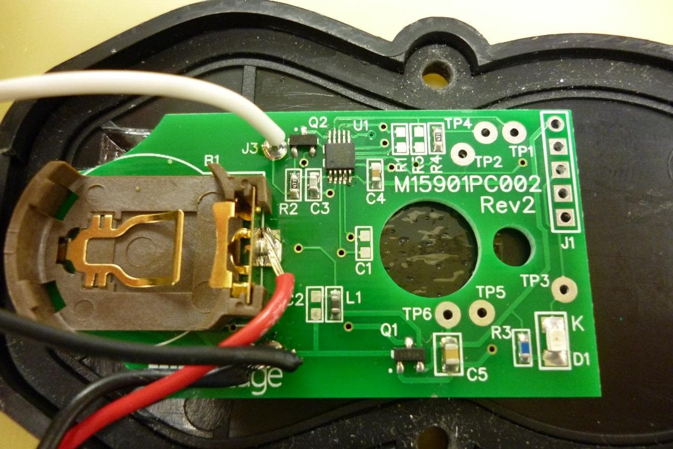
OYE-MTF10
Jun 22, 2014RF Link
Equipment Class
DXX - Part 15 Low Power Communication Device Transmitter
OYE-MWT120
May 01, 2013318 MHz SINGLE CHANNEL TRANSMITTER
Equipment Class
DSC - Part 15 Security/Remote Control Transmitter
OYE-MDTR3
Feb 02, 2012CONTROL ALARM TRANSMITTER
Equipment Class
DSC - Part 15 Security/Remote Control Transmitter