OYE-MEL315Monitored Edge Link
Miller Edge, Inc.
Click to zoom
Application Details
- Equipment Class
- DSC - Part 15 Security/Remote Control Transmitter
- Date of Grant
- Aug 11, 2014
- Application Purpose
- Original Equipment
- Date of Application
- Aug 11, 2014
- Equipment Note
- Monitored Edge Link
- Frequency Range
- 315.00000000 - 315.00000000
- Company
- Miller Edge, Inc.
- Country
- United States
Documents & Files
Document Text
Text extracted from the exhibit documents filed with the FCC. Open a document above to read the original.
Users Manual
2 - 1 . O p e n a n d u n p a c k t h e a n t e n n a , b a t t e r i e s , t r a n s m i t t e r a n d r e c e i v e r u n i t s . 2 - 2 . L o o s e n s c r e w s f r o m t h e t o p c o v e r a n d r e m o v e t h e l i d . 2 - 3 . R e m o v e t h e T r a n s m i t t e r P C B b y p u l l i n g u p w a r d o n o n e o f t h e s i l i c o n e c a p s . 2 - 4 . R o u t e t h e w i r e s f r o m t h e m o n i t o r e d e d g e t h r o u g h t h e s t r a i n r e l i e f c a b l e f i t t i n g f o r a p p r o x i m a t e l y f o u r i n c h e s . S t r i p t h e i n s u l a t i o n f r o m t h e t w o w i r e s b a c k ¼ ” a n d s e c u r e t h e w i r e s i n t h e t e r m i n a l b l o c k m a r k e d S E 1 . ( N o t p o l a r i z e d . ) A K n o c k o u t ( K . O . ) s w i t c h m a y b e w i r e d t o t h e T x t e r m i n a l s t r i p m a r k e d K O . ( E i t h e r n o r m a l l y o p e n o r n o r m a l l y c l o s e d s w i t c h e s m a y b e u s e d . ) 2 - 5 . P l a c e t h e t w o A A L i t h i u m b a t t e r i e s i n t h e i r h o l d e r s i n t h e p r o p e r d i r e c t i o n , p a y i n g a t t e n t i o n t o t h e ( + ) a n d ( - ) e n d s . 2 - 6 . T u c k t h e w i r e s c o n n e c t e d t o t h e S E t e r m i n a l b l o c k n e a t l y b e t w e e n t h e b a t t e r i e s a n d p u l l t h e e x c e s s w i r e b a c k t h r o u g h t h e s t r a i n r e l i e f . R e - s e a t t h e P C B i n t h e c a s e , a n d s e c u r e l y t i g h t e n t h e c a b l e f i t t i n g . 2 - 7 . S e t t h e T e r m i n a t i o n T y p e s w i t c h t o e i t h e r 1 0 K o r D C . ( s e e A p p e n d i x ) T h i s s e l e c t i o n m u s t m a t c h t h e T e r m i n a t i o n T y p e i n t h e S a f e t y E d g e . 2 - 8 . A d d r e s s S w i t c h e s S e t t h e G r o u p ( r e d ) a n d A d d r e s s ( b l u e ) s w i t c h e s t o t h e d e s i r e d p o s i t i o n . ( N o t e t h e s e t t i n g s f o r r e f e r e n c e w h e n s e t t i n g u p t h e R e c e i v e r . ) I f t h e G r o u p s w i t c h i s s e t t o 0 , t h e A d d r e s s s w i t c h m a y b e s e t t o a n y p o s i t i o n b e t w e e n 0 a n d F . I f t h e G r o u p s w i t c h i s s e t t o 1 , t h e A d d r e s s s w i t c h m a y b e s e t t o a n y p o s i t i o n b e t w e e n 0 a n d B . ( T h e r e m a i n i n g p o s i t i o n s , C , D , E , a n d F a r e r e s e r v e d f o r f a c t o r y t e s t . ) P.O. Box 159 • West Grove, PA 19390 • 800-220-3343 • 610-869-4422 • Fax: 610-869-4423 • www.milleredge.com 6809 South Harl Ave., Suite A • Tempe, AZ 85283 • 800-887-3343 • 480-755-3565 • Fax: 480-755-3558 MEL-K20_Inst_20140708 Model # MEL-K20 I N S T A L L A T I O N I N S T R U C T I O N S IMPORTANT: READ AND UNDERSTAND ALL INSTRUCTIONS BEFORE BEGINNING INSTALLATION. Parts List Kit Contents: 1. MEL-TX20 Transmitter Unit 2. MEL-RX20 Receiver Unit 3. Receiver Antenna 4. (2) AA Lithium Batteries 5. 3 ft. 20 AWG lead wire 6. (4) #6 Pan Head Transmitter Mounting Screws 1- PART NUMBER 2-Install Transmitter and Test T h e M o n i t o r e d E d g e L i n k ( M E L ) t r a n s m i t t e r / r e c e i v e r s y s t e m i s i n t e n d e d t o p r o v i d e a w i r e l e s s c o n n e c t i o n b e t w e e n a m o n i t o r e d s a f e t y e d g e a n d a m o t o r i z e d o p e r a t o r t h a t c o n t r o l s t h e a s s o c i a t e d d o o r o r g a t e . M E L m e e t s t h e U L - 3 2 5 / 2 0 1 0 r e q u i r e m e n t s f o r m o n i t o r e d d e v i c e s a n d h a s b e e n c e r t i f i e d a s a U L 3 2 5 r e c o g n i z e d c o m p o n e n t . I t i s d e s i g n e d f o r u s e o n o p e r a t o r s t h a t c o m p l y w i t h U L 3 2 5 - 2 0 1 0 u s i n g a T 2 o r T 3 t e r m i n a t e d e d g e s e n s o r . Required: 1. 1/8” Flat blade screwdriver 2. 1/4” Flat blade screwdriver 3. T2 (10K/Blue Band) or T3 (Diode- Capacitor/Red Band)Terminated Sensing Edge Recommended: VOM for test purposes Mounting screws as required for receiver T OP LID SCREWS TRANSMITTER PCB TEST BUTTON TERMINATION SELECTION SILICONE CAP (4) STRAIN RELIEF FITTING (2-6) EDGE WIRING TO TERMINAL BLOCK MEL-K20_Inst_20140708_WPE Instuctions 7/16/14 12:01 PM Page 1 P.O. Box 159 • West Grove, PA 19390 • 800-220-3343 • 610-869-4422 • Fax: 610-869-4423 • www.milleredge.com 6809 South Harl Ave., Suite A • Tempe, AZ 85283 • 800-887-3343 • 480-755-3565 • Fax: 480-755-3558 2-9. Momentarily press the TEST button. The Green Tx Data LED should flash. (The Red Low Battery LED will only light when the batteries fall below 2.4v.) 2-10. Mount the Transmitter to the door or gate using #6 - 20 x 3/4” self-drilling screws.The mounting holes are located under the Top Lid Screws. Mount the transmitter with the wire strain relief facing down or to the side. 2 -11. Replace the cover on the Transmitter and tighten the screws taking care to align the lid. *Note the alignment pin located in the upper left corner. 3-Install Receiver and Test 3-1. Remove lid of the Receiver Unit. 3-2. Set the Group (red) and Address (blue) switches to match the transmitter settings. 3-3. Mount the receiver close to the operator and in-the-line-of-sight of the transmitter using the mounting holes, as shown. 3-4. *Connect the receiver’s PE (Photo-Eye) output to the operator’s PE input terminals using Green and White wires. (Operator terminal label naming may differ. Contact factory for support). 3-5. Connect the Black and Red wires to a 12 or 24V ac/dc source. 3-6. Attach the antenna to the receiver RF board. 3-7. Preliminary Test : Confirm that the Transmitter and Receiver are powered ON. Activate the Safety Edge (or monitored device). The Address Valid Yellow LED on the Receiver should flash momentarily. If the Address Valid LED does not flash, check that the Group and Address switches match the transmitter settings. Confirm that the Photo-Eye and Safety Edge LEDs are lit while the safety edge is held active. Note that the Photo-Eye and Safety Edge LEDs go O…
Text truncated - open the document above for the full version.
Test Report
Certificates and reports shall not be reproduced except in full, without the written permission of Washington Laboratories, Limited. FCC Certification Test Report For the MILLER EDGE MEL-TX20 FCC ID: OYE-MEL315 WLL JOB# 13469-01 Rev 0 June 6, 2014 Prepared for: Miller Edge 300 N Jennersville Road West Grove, PA 19390 Prepared By: Washington Laboratories, Ltd. 7560 Lindbergh Drive Gaithersburg, Maryland 20879 Testing Certificate AT-1448 Miller Edge MEL-TX20 FCC Test Report June 2014 WLL Report #13469-01 - Page 1 of 22 - © 2014 Washington Laboratories, Ltd. FCC Certification Test Report for the MILLER EDGE MEL-TX20 FCC ID: OYE-MEL315 WLL JOB# 13469-01 Rev 0 June 6, 2014 Prepared by: __________________________ Steven Dovell Compliance Engineer Reviewed by: __________________________ Steven D. Koster Vice President Miller Edge MEL-TX20 FCC Test Report June 2014 WLL Report #13469-01 - Page 2 of 22 - © 2014 Washington Laboratories, Ltd. Abstract This report has been prepared on behalf of Miller Edge to support the attached Application for Equipment Authorization. The test report and application are submitted for an Intentional Radiator under Part 15.231 (10/2013) of the FCC Rules and Regulations. This Certification Test Report documents the test configuration and test results for a Miller Edge MEL-TX20. Testing was performed on an Open Area Test Site (OATS) of Washington Laboratories, Ltd, 7560 Lindbergh Drive, Gaithersburg, MD 20879. Site description and site attenuation data have been placed on file with the FCC's Sampling and Measurements Branch at the FCC laboratory in Columbia, MD. The Industry Canada OATS numbers are 3035A-1 and 3035A-2 for Washington Laboratories, Ltd. Site 1 and Site 2, respectively. Washington Laboratories, Ltd. has been accepted by the FCC and approved by ACLASS under Certificate AT-1448 as an independent FCC test laboratory. The Miller Edge MEL-TX20 complies with the limits for an Intentional Radiator device under FCC Part 15.231. Miller Edge MEL-TX20 FCC Test Report June 2014 WLL Report #13469-01 - Page 3 of 22 - © 2014 Washington Laboratories, Ltd. Table of Contents Abstract ........................................................................................................................................................2 1 Introduction ......................................................................................................................................4 1.1 Compliance Statement ................................................................................................................ 4 1.2 Test Scope ................................................................................................................................... 4 1.3 Contract Information ................................................................................................................... 4 1.4 Test Dates .................................................................................................................................... 4 1.5 Test and Support Personnel ........................................................................................................ 4 1.6 Abbreviations .............................................................................................................................. 5 2 Equipment Under Test .....................................................................................................................6 2.1 EUT Identification & Description ............................................................................................... 6 2.2 Test Configuration ...................................................................................................................... 6 2.3 Testing Algorithm ....................................................................................................................... 6 2.4 Test Location............................................................................................................................... 7 2.5 Measurements ............................................................................................................................. 7 2.5.1 References ............................................................................................................................... 7 2.6 Measurement Uncertainty ........................................................................................................... 7 3 Test Equipment ................................................................................................................................9 4 Test Results ....................................................................................................................................10 4.1 Duty Cycle Correction .............................................................................................................. 10 4.2 Transmit Turnoff Time (FCC Part §15.231(a) (2)) ................................................................... 14 4.3 FCC Part §15.231(a) (3) Compliance ....................................................................................... 15 4.4 Occupied Bandwidth: (FCC Part §2.1049) ............................................................................... 17 4.5 Radiated Emissions: (FCC Part §2.1053) ................................................................................. 18 4.5.1 Test Procedure ...................................................................................................................... 18 4.6 Conducted Emissions (AC Power Line) ................................................................................... 22 4.7 Receiver Emissions ................................................................................................................... 22 List of Tables Table 1: Device Summary ........................................................................................................................... 6 Table 2: Expanded Uncertainty…
Text truncated - open the document above for the full version.
Test Report
1 | Page August 7, 2014 Response to comments of: RE: ATCB015980 – Original Equipment Certification Application FCC ID: OYE-MEL315 for Miller Edge Inc. After a review of the submitted information, I have a few comments on the above referenced Application. 1 See next page.. 2 | Page For Your Information – Table 6 in the submitted test report shows the wrong emission limit for the emissions at 1575 MHz, 2205 MHz and 2835 MHz. These previous frequencies are in the restricted bands listed in Section 15.205 of the FCC Rules and the limits are 5000 uV/m @ 3m (peak) and 500 uV/m @ 3m (average) not the levels shown in the table. Since none of the reported emission levels are above 500 uV/m @ 3m, I will ignore this problem. However I will place a copy of this FYI into the test report exhibit to explain how these levels show compliance. Noted James Ritter EMC compliance Engineer
Test Setup Photos
1 | Page WLL XXXXX Test Setup Photos Miller Edge ‐ 13469 2 | Page WLL XXXXX
Contact Information
Applicant
Tim Castello
Technical Contact
Washington Laboratories, Ltd.Steve Koster
[email protected]301-216-1500
7560 Lindbergh Drive · Gaithersburg, Maryland · United States
Test Firm
Washington Laboratories, Ltd.Steve Koster
Technical Specifications
| # | Rule Parts | Frequency Range | Power Output |
|---|---|---|---|
| 1 | 15.231 | 315 MHz - 315 MHz | - |
Other Applications from Miller Edge, Inc.

OYE-MEL916
Aug 27, 2014Monitored Edge Link
Equipment Class
DXX - Part 15 Low Power Communication Device Transmitter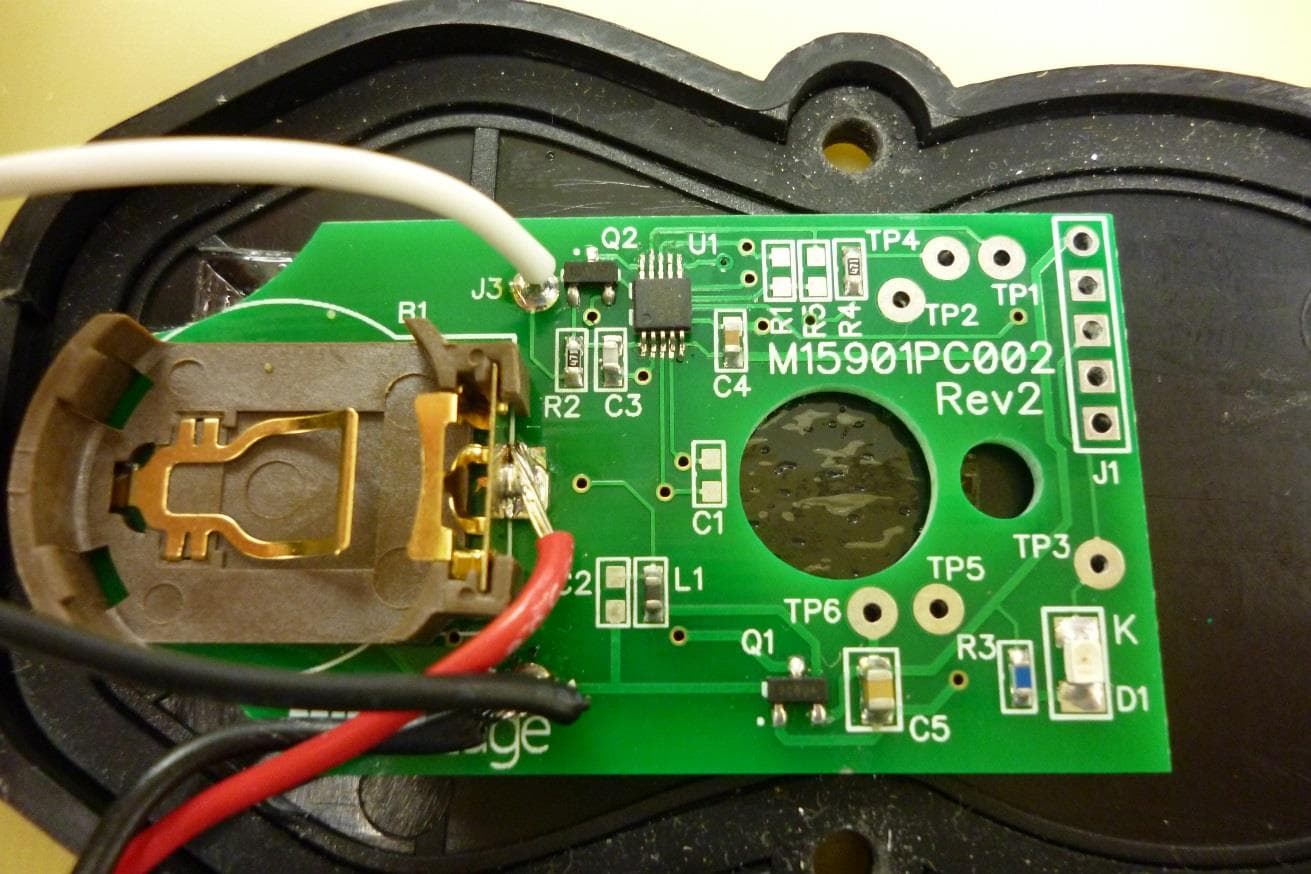
OYE-MTF10
Jun 22, 2014RF Link
Equipment Class
DXX - Part 15 Low Power Communication Device Transmitter
OYE-MWT120
May 01, 2013318 MHz SINGLE CHANNEL TRANSMITTER
Equipment Class
DSC - Part 15 Security/Remote Control Transmitter
OYE-MDTR303
Feb 06, 2012CONTROL ALARM TRANSMITTER
Equipment Class
DSC - Part 15 Security/Remote Control Transmitter
OYE-MDTR3
Feb 02, 2012CONTROL ALARM TRANSMITTER
Equipment Class
DSC - Part 15 Security/Remote Control Transmitter