OYE-MTF10RF Link
Miller Edge, Inc.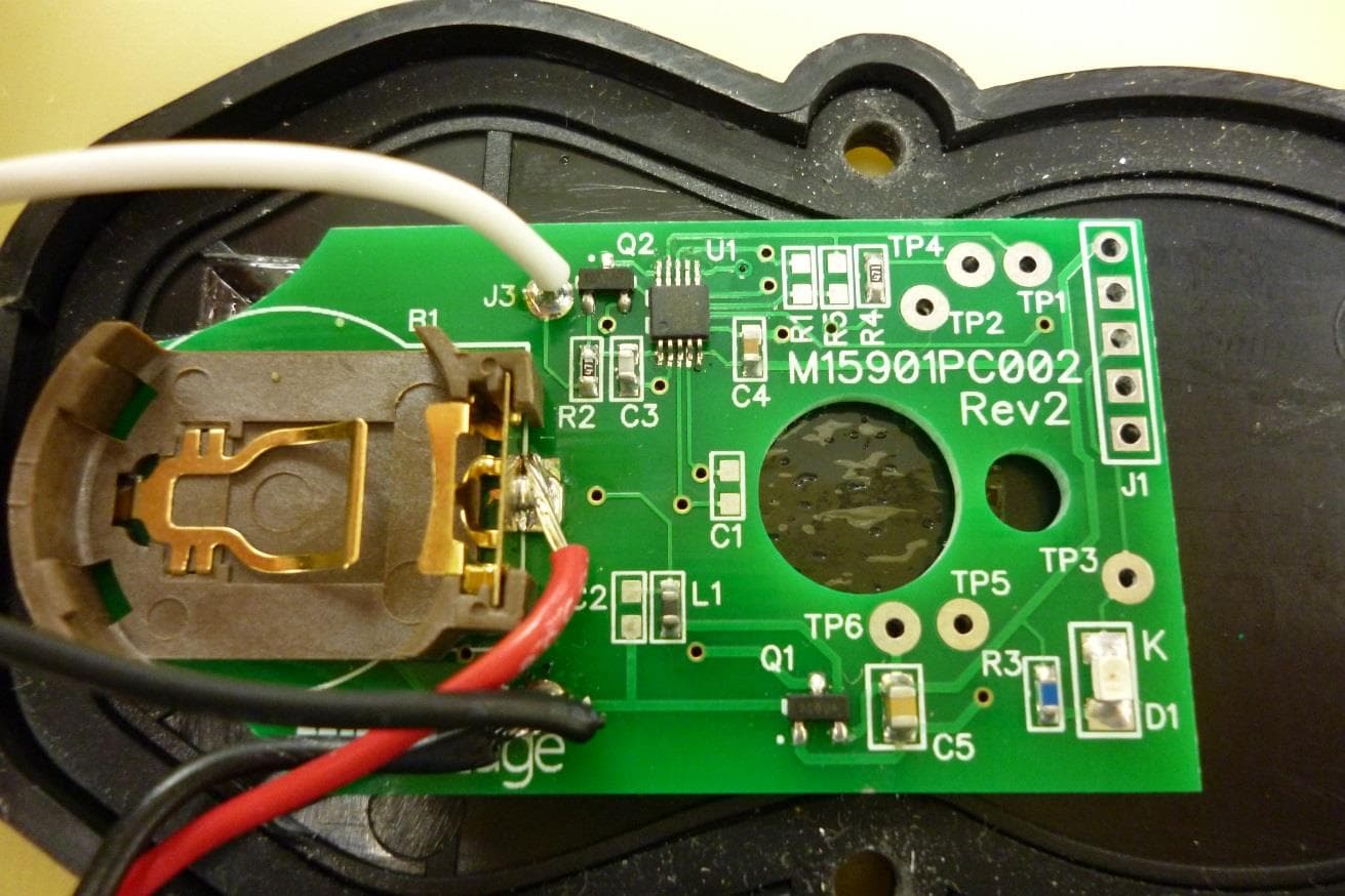
Click to zoom
Application Details
- Equipment Class
- DXX - Part 15 Low Power Communication Device Transmitter
- Date of Grant
- Jun 22, 2014
- Application Purpose
- Original Equipment
- Date of Application
- Jun 19, 2014
- Equipment Note
- RF Link
- Frequency Range
- 910.00000000 - 920.00000000
- Company
- Miller Edge, Inc.
- Country
- United States
Documents & Files
Document Text
Text extracted from the exhibit documents filed with the FCC. Open a document above to read the original.
Users Manual
AW12-RF/MRF-01 INSTALLATION INSTRUCTIONS Preliminary 1- PARTS LIST PART NUMBERS -AW12-RF Single Channel Transmitter/Air Wave™ Switch Assembly -MRF-01 Single Channel Receiver -P/N=? Battery, CR2032 -(4) #6-20x3/4”, Screw, Self-Drilling 2- INSTALL TRANSMITTER/AIR WAVE™SWITCH ASSY -Open box, unpack battery and remove lid from the AW12-RF. -Install CR2032 battery as shown with the “+” side up. Notice that the Red LED blinks once upon insertion. -Now position & attach, with provided screws, your AW12-RF to your bottom angle or end stile of your door. Replace lid. -Now, dependent upon your “kit”, make the necessary airline connections. 3- INSTALL RECEIVER -Open box, remove lid from the MRF-01 receiver. -Position receiver on operator, so that its wiring will reach the operator terminal strip. Keep in mind that the Green antenna wire must be exposed to the AW12-RF Transmitter/Air Wave™ Switch. It cannot be behind any type of metal. -Connect the Red (+) & Black (-) to your 24VAC/DC source. The White wire connects to a low voltage COMMON terminal. The Yellow wire connects to your EDGE/SAFETY terminal. 4- PROGRAMMING -Apply power to the receiver. -Green Power LED stays on; Channel 1 Red LED will be blinking. -To enter “Learn” mode simply press your fingertip onto CH1 (in the LEARN BUTTON section of the PCB). The Red LED remains on and the Amber Learn LED will begin to blink. -Activate the edge & note the Red & Amber LED’s will blink alternately rapidly. Then the Red LED will go out & the Amber LED remains on. -Channel 1 is now programmed. -To start-over/erase programming, press and hold CH1 again for 3 seconds, LED’s will blink for 5 seconds & then go into fault mode. 5- TEST SAFETY EDGE -Ensure that your door stops/reverses when safety edge is activated during close cycle. LED INDICATORS LED Color Function Description Green Power Always On Yellow Status Usually On – Off if right out of the box, no transmitter associated. Wink Off once per TX message received. Blinks rapidly during Learn Mode. Red (per channel) Relay State Learn Mode Off when Relay is Clear. On when Relay is in Fault. Blink very slowly for Low Battery. Blink slowly if no TX has been associated. On when this channel is in Learn Mode (Yellow blinking). Blinks rapidly when Learn Mode is complete. P.O. Box 159 • West Grove, PA 19390 • 800-220-3343 • 610-869-4422 • Fax: 610-869-4423 • www.milleredge.com 6809 South Harl Ave., Suite A • Tempe, AZ 85283 • 800-887-3343 • 480-755-3565 • Fax: 480-755-3558 5- Specifications and Controls: Transmitter Unit Frequency: 915 MHz. FSK Modulation. Indicator Lights: Red LED: Tx Data Power Source: Batteries: CR2032 Coincell. 3.0VDC Lithium. Dimensions: Antenna: Integral PCB loop. Response Time: Nominal 70 msec; Safety Edge Input to Receiver Relay Contact Output. 6-Specifications and Controls: Receiver Unit Indicator Lights: Green LED: Power on; Red LED: Relay energized, indicates safety edge activation; Yellow LED: Status Power Source: 10 to 40 VDC, 10-30 VAC (RMS) Power Consumption: 16 mA (Idle) with Relay Off; 53 mA (avg.) with Relay On Dimensions: 4.9”w x 3.75”h x 1.2”d Cable Connections: Integral 18” wiring with #8 spade lugs. Maximum Operating Distance: 100 Feet 7- FCC Compliance FCC ID: OYE-MTF10 THIS DEVICE COMPLIES WITH PART 15 OF THE FCC RULES. OPERATION IS SUBJECT TO THE FOLLOWING TWO CONDITIONS. 1) THIS DEVICE MAY NOT CAUSE HARMFUL INTERFERENCE AND 2) THIS DEVICE MUST ACCEPT ANY INTERFERENCE RECEIVED INCLUDING INTERFERENCE THAT MAY CAUSE UNDESIRED OPERATION. This equipment has been tested and found to comply with the limits for a Class B digital device, pursuant to Part 15 of the FCC Rules. These limits are designed to provide reasonable protection against harmful interference in a residential installation. This equipment generates, uses and can radiate radio frequency energy and, if not installed and used in accordance with the instructions, may cause harmful interference to radio communications. However, there is no guarantee that interference will not occur in a particular installation. If this equipment does cause harmful interference to radio or television reception, which may be determined by turning the equipment off and on, the user is encouraged to try to correct the interference by one or more of the following measures: 1- Re-orient or relocate the receiver antenna 2- Increase the separation between the equipment and the receiver 3- Connect the equipment into an outlet on a circuit different from that to which the receiver is connected. 4- Consult the dealer or an experienced radio/TVtechnician for help. Changes or Modifications Not Expressly Approved By The Party Responsible For Compliance Could Void The User’s Authority To Operate The Equipment.
Users Manual
2-1. Open and unpack the battery and remove lid from the AW14-RF. 2-2. Install the CR2032 battery as shown with the “+” side up. Notice that the RED LED blinks once upon insertion. Replace the lid of the AW14-RF 2-3 Position and attach the AW14-RF to the bottom angle or end stile of the door. 2-4 Depending on the configuration, make the necessary airline connections. P.O. Box 159 • West Grove, PA 19390 • 800-220-3343 • 610-869-4422 • Fax: 610-869-4423 • www.milleredge.com 6809 South Harl Ave., Suite A • Tempe, AZ 85283 • 800-887-3343 • 480-755-3565 • Fax: 480-755-3558 Model # AW14-RF I N S T A L L A T I O N I N S T R U C T I O N S I MPORTANT: READ AND UNDERSTAND ALL INSTRUCTIONS BEFORE BEGINNING INSTALLATION. Parts List 1. AW14-RF Transmitter/Air Wave Switch Assembly 2. Battery, CR2032 1- PART NUMBER 2-Install Transmitter / Air Switch Assembly Tools Required: 1. 1/8” Phillips Head Screwdriver 2. Mounting Screws (not supplied) Pending 3-Adjust The Switch Sensitivity 3-1 The AW14 is factory set and should rarely need to be adjusted. If you determine that the switch sensitivity is not correct, to make the switch more sensitive, turn the adjustment screw clock-wise. This will move the screw closer to the diaphragm inside the switch, thus less air movement is required to activate the switch (LED will Blink). Longer edges will require more sensitivity. Too sensitive will cause unwanted activations caused from door vibration. 2-12-2 2-3 2-4 3-1 DRAFT The AW14-RF switch offers installation time savings and improved visual aesthetics as there is no need to hard wire a coil cord or retracting reel. The AW14-RF switch kit includes a MRF-01 receiver which is wired to the motor controls. Kits may be installed on a doors up to18 feet wide. 5-Transmitter Specifications 6-FCC Compliance P.O. Box 159 • West Grove, PA 19390 • 800-220-3343 • 610-869-4422 • Fax: 610-869-4423 • www.milleredge.com 6809 South Harl Ave., Suite A • Tempe, AZ 85283 • 800-887-3343 • 480-755-3565 • Fax: 480-755-3558 Frequency:915 MHz. FSK Modulation Indicator Light:Red LED. Blinks when data is sent. Power Source:CR2032 Coincell Battery 3.0VDC Lithium Antenna: Integral PCB loop Response Time:Nominal 100 msec, Safety Edge Input to Receiver Relay Contact Output Operating Distance:50 feet minimum, Up to 100 feet depending on conditions Operating Temperature:14 o F - 140 o F (-10 o C - + 60 o C) (Battery Limit) Transmitter Model: AW14-RF FCC ID: OYE-MTF10 THIS DEVICE COMPLIES WITH PART 15 OF THE FCC RULES. OPERATION IS SUBJECT TO THE FOLLOWING TWO CONDITIONS: 1) THIS DEVICE MAY NOT CAUSE HARMFUL INTERFERENCE, AND 2) THIS DEVICE MUST ACCEPT ANY INTERFERENCE RECEIVED INCLUDING INTERFERENCE THAT MAY CAUSE UNDESIRED OPERATION. Changes or Modifications Not Expressly Approved By The Party Responsible For Compliance Could Void The User Authority To Operate The Equipment. 4-Test Safety Edge 3-1 Ensure that the door stops/reverses when the sensing edge is activated during the close cycle. This equipment has been tested and found to comply with the limits for a Class B digital device, pursuant to Part15 of the FCC Rules.These limits are designed to provide reason- able protection against harmful interference in a residential installation. This equipment generates, uses and can radiate radio frequency energy and, if not installed and used in accordance with the instructions, may cause harmful interference to radio communications. However, there is no guarantee that interference will not occur in a particular installation. If this equipment does cause harmful interference to radio or television reception, which may be determined by turning the equipment off and on, the user is encouraged to try to correct the interference by one or more of the following measures: 1- Re-orient or relocate the receiver antenna 2- Increase the separation between the equipment and the receiver 3- Connect the equipment into an outlet on a circuit different from that to which the receiver is connected. 4- Consult the dealer or an experienced radio/TV technician for help
Users Manual
2-1. Open and unpack the battery and remove lid from the PS20-RF. 2-2. Install the CR2032 battery as shown with the “+” side up. Notice that the RED LED blinks once upon insertion. 2-3. Replace the lid of the PS20-RF. 2-4. Insert the PS20-RF nipple into either end of the Hard Hose. 2-5. Insert remaining Hard Hose end into the Gum Rubber Hose located inside the bottom astragal. 2-6. Position and attach the PS20-RF to the bottom angle or end stile of the door, taking care not to pinch close the Hard Rubber or Gum Rubber Hose. P.O. Box 159 • West Grove, PA 19390 • 800-220-3343 • 610-869-4422 • Fax: 610-869-4423 • www.milleredge.com 6809 South Harl Ave., Suite A • Tempe, AZ 85283 • 800-887-3343 • 480-755-3565 • Fax: 480-755-3558 Model # PS20-RF I N S T A L L A T I O N I N S T R U C T I O N S I MPORTANT: READ AND UNDERSTAND ALL INSTRUCTIONS BEFORE BEGINNING INSTALLATION. Parts List 1. PS20-RF Transmitter/Air Switch Combination 2. HRH-375, Hard Hose, 4” 3. Battery, CR2032 1- PART NUMBER 2-Install Transmitter / Air Switch Assembly Tools Required: 1. 1/8” Phillips Head Screwdriver 2. Mounting Screws (not supplied) Pending The PS20RF switch offers installation time savings and improved visual aesthetics as there is no need to hard wire a coil cord or retracting reel. PS20RF switch includes a receiver which is wired to the motor controls. PS20 kits are available as either hard-wired (PS20A) or wireless (PS20RF) complete with receiver. Kits may be installed on a doors up to 18 feet wide. 2-12-2 2-32-4 2-4 2-5 2-6 2-6 DRAFT 4-TransmitterSpecifications 5-FCC Compliance P.O. Box 159 • West Grove, PA 19390 • 800-220-3343 • 610-869-4422 • Fax: 610-869-4423 • www.milleredge.com 6809 South Harl Ave., Suite A • Tempe, AZ 85283 • 800-887-3343 • 480-755-3565 • Fax: 480-755-3558 Frequency:915 MHz. FSK Modulation Indicator Light:Red LED. Blinks when data is sent. Power Source:CR2032 Coincell Battery 3.0VDC Lithium Antenna: Integral PCB loop Response Time:Nominal 100 msec, Safety Edge Input to Receiver Relay Contact Output Operating Distance:50 feet minimum, Up to 100 feet depending on conditions Operating Temperature:14 o F - 140 o F (-10 o C - + 60 o C) Transmitter Model: PS20-RF FCC ID: OYE-MTF10 THIS DEVICE COMPLIES WITH PART 15 OF THE FCC RULES. OPERATION IS SUBJECT TO THE FOLLOWING TWO CONDITIONS: 1) THIS DEVICE MAY NOT CAUSE HARMFUL INTERFERENCE, AND 2) THIS DEVICE MUST ACCEPT ANY INTERFERENCE RECEIVED INCLUDING INTERFERENCE THAT MAY CAUSE UNDESIRED OPERATION. 3-Test Safety Edge 3-1 Ensure that the door stops/reverses when the sensing edge is activated during the close cycle. Changes or Modifications Not Expressly Approved By The Party Responsible For Compliance Could Void The User Authority To Operate The Equipment. This equipment has been tested and found to comply with the limits for a Class B digital device, pursuant to Part15 of the FCC Rules.These limits are designed to provide reason- able protection against harmful interference in a residential installation. This equipment generates, uses and can radiate radio frequency energy and, if not installed and used in accordance with the instructions, may cause harmful interference to radio communications. However, there is no guarantee that interference will not occur in a particular installation. If this equipment does cause harmful interference to radio or television reception, which may be determined by turning the equipment off and on, the user is encouraged to try to correct the interference by one or more of the following measures: 1- Re-orient or relocate the receiver antenna 2- Increase the separation between the equipment and the receiver 3- Connect the equipment into an outlet on a circuit different from that to which the receiver is connected. 4- Consult the dealer or an experienced radio/TV technician for help
External Photos
Miller Edge, Inc. FCC ID: OYE-MTF10 AW12-RF Internal External AW14-RF Internal External PS20-RF Internal External
ID Label/Location Info
REVISIONS ZONEREV.DESCRIPTIONDATEAPPROVED 000RELEASE TO MANUFACTURING ECR 12725-22-14DL NOTES: UNLESS OTHERWISE SPECIFIED BLACK TEXT ON WHITE LABEL1. FACESTOCK - UL WHITE POLYESTER L344 @ 2.02. LAMINATION - LAMINCLTI1.0S80201.0PET3. 1.06 .63 REV. A DWG. NO. SIZE WEIGHT: 000 MATERIAL PS20-RF PROPRIETARY AND CONFIDENTIAL 228-70A FINISH DO NOT SCALE DRAWING APPLICATION USED ON NEXT ASSY FCC LABEL DRAWING IS THE SOLE PROPERTY OF REPRODUCTION IN PART OR AS A WHOLE PROHIBITED. COMMENTS: SHEET 1 OF 1 Q.A. MFG APPR. ENG APPR. CHECKED <INSERT COMPANY NAME HERE>. ANY WITHOUT THE WRITTEN PERMISSION OF 5-20-14 NAME <INSERT COMPANY NAME HERE> IS DATE DUFFY DRAWN THE INFORMATION CONTAINED IN THIS DIMENSIONS ARE IN INCHES TOLERANCES: FRACTIONAL ANGULAR: MACH BEND TWO PLACE DECIMAL THREE PLACE DECIMAL SCALE:2:1 REV. REPRODUCTION IN PART OR AS A WHOLE DWG. NO. SIZE WEIGHT: 000 MATERIAL AW-14-RF PROPRIETARY AND CONFIDENTIAL 228-70 FINISH DO NOT SCALE DRAWING APPLICATION USED ON NEXT ASSY FCC LABEL DRAWING IS THE SOLE PROPERTY OF A PROHIBITED. COMMENTS: SHEET 1 OF 1 Q.A. MFG APPR. ENG APPR. CHECKED <INSERT COMPANY NAME HERE>. ANY WITHOUT THE WRITTEN PERMISSION OF 5-20-14 NAME <INSERT COMPANY NAME HERE> IS DATE DUFFY DRAWN THE INFORMATION CONTAINED IN THIS DIMENSIONS ARE IN INCHES TOLERANCES: FRACTIONAL ANGULAR: MACH BEND TWO PLACE DECIMAL THREE PLACE DECIMAL SCALE:2:1 REVISIONS ZONEREV.DESCRIPTIONDATEAPPROVED 000RELEASE TO MANUFACTURING ECR 12725-22-14DL NOTES: UNLESS OTHERWISE SPECIFIED BLACK TEXT ON WHITE LABEL1. FACESTOCK - UL WHITE POLYESTER L344 @ 2.02. LAMINATION - LAMINCLTI1.0S80201.0PET3. 1.06 .63 REVISIONS ZONEREV.DESCRIPTIONDATEAPPROVED 000RELEASE TO MANUFACTURING ECR 12725-22-14DL NOTES: UNLESS OTHERWISE SPECIFIED BLACK TEXT ON WHITE LABEL1. FACESTOCK - UL WHITE POLYESTER L344 @ 2.02. LAMINATION - LAMINCLTI1.0S80201.0PET3. REPRODUCTION IN PART OR AS A WHOLE DWG. NO. SIZE WEIGHT: 000228-70B REV. PROPRIETARY AND CONFIDENTIAL THE INFORMATION CONTAINED IN THIS DUFFY MATERIAL FINISH DO NOT SCALE DRAWING APPLICATION USED ON DRAWING IS THE SOLE PROPERTY OF A PROHIBITED. COMMENTS: SHEET 1 OF 1 Q.A. MFG APPR. ENG APPR. CHECKED DRAWN <INSERT COMPANY NAME HERE> IS WITHOUT THE WRITTEN PERMISSION OF NEXT ASSY FCC LABEL <INSERT COMPANY NAME HERE>. ANY NAME 5-20-14 DATE AW12-RF DIMENSIONS ARE IN INCHES TOLERANCES: FRACTIONAL ANGULAR: MACH BEND TWO PLACE DECIMAL THREE PLACE DECIMAL SCALE:2:1 1.06 .63
Internal Photos
Miller Edge, Inc. FCC ID: OYE-MTF10 AW12-RF Internal External AW14-RF Internal External PS20-RF Internal External
Test Report
Certificates and reports shall not be reproduced except in full, without the written permission of Washington Laboratories, Limited. FCC Certification Test Report FCCID: OYE-MTF10 MILLER EDGE RF LINK WLL REPORT# 13314-01 Rev 1 April 16, 2014 Revised June 13, 2014 Prepared for: Miller Edge 300 N Jennersville Road West Grove, PA 19390 Prepared By: Washington Laboratories, Ltd. 7560 Lindbergh Drive Gaithersburg, Maryland 20879 Testing Certificate AT-1448 Miller Edge RF Link FCC Certification Test Report April, 2014 WLL Report #13314-01 Rev 1 - ii - © 2014 Washington Laboratories, Ltd. FCC Certification Test Report For the MILLER EDGE RF LINK FCC ID: OYE-MTF10 WLL REPORT# 13314-01 Rev 1 April 16, 2014 Revised June 13, 2014 Prepared by: ___________________________ John P. Repella Compliance Engineer Reviewed by: ____________________________ Steven D. Koster Vice President Miller Edge RF Link FCC Certification Test Report April, 2014 WLL Report #13314-01 Rev1 - iii - © 2014 Washington Laboratories, Ltd. Abstract This report has been prepared on behalf of Miller Edge to support the attached Application for Equipment Authorization. The test report and application are submitted for an Intentional Radiator under Part 15.249 (10/2013) of the FCC Rules. This Certification Test Report documents the test configuration and test results for Miller Edge RF Link. Testing was performed on an Open Area Test Site (OATS) of Washington Laboratories, Ltd, 7560 Lindbergh Drive, Gaithersburg, MD 20879. Site description and site attenuation data have been placed on file with the FCC's Sampling and Measurements Branch at the FCC laboratory in Columbia, MD. Washington Laboratories, Ltd. has been accepted by the FCC and approved by ACLASS under Certificate AT-1448 as an independent FCC test laboratory. The Miller Edge RF Link complies with the limits for an Intentional Radiator device under FCC Part 15.249. Revision History Reason Date Rev 0 Initial Release April 16, 2014 Rev 1 Corrected typographical errors added 910MHz bandwidth plot June 13, 2014 JR Miller Edge RF Link FCC Certification Test Report April, 2014 WLL Report #13314-01 Rev1 - iv - © 2014 Washington Laboratories, Ltd. Table of Contents Abstract ........................................................................................................................................... ii 1 Introduction ..............................................................................................................1 1.1 Compliance Statement .................................................................................................... 1 1.2 Test Scope ....................................................................................................................... 1 1.3 Contract Information ....................................................................................................... 1 1.4 Test Dates ........................................................................................................................ 1 1.5 Test and Support Personnel ............................................................................................ 1 1.6 Abbreviations .................................................................................................................. 2 2 Equipment Under Test .............................................................................................3 2.1 EUT Identification & Description ................................................................................... 3 2.2 Test Configuration .......................................................................................................... 4 2.3 Testing Algorithm ........................................................................................................... 4 2.4 Test Location................................................................................................................... 4 2.5 Measurements ................................................................................................................. 4 2.5.1 References ................................................................................................................... 4 2.6 Measurement Uncertainty ............................................................................................... 4 2.7 Test Equipment ............................................................................................................... 6 3 Test Results ..............................................................................................................7 3.1 Duty Cycle Correction .................................................................................................... 7 3.2 Occupied Bandwidth: (FCC Part §2.1049) ................................................................... 10 3.3 Radiated Emissions: (FCC Part §2.1053, RSS210 A2.9) ............................................. 12 3.3.1 Test Procedure .......................................................................................................... 12 List of Tables Table 1: Device Summary ............................................................................................................... 3 Table 2: Expanded Uncertainty ....................................................................................................... 5 Table 3: Test Equipment List .......................................................................................................... 6 Table 4: Occupied Bandwidth Results .......................................................................................... 10 Table 5: Radiated Emissions Limits ............................................................................................. 12 Table 6: Radiated Emission Test Data (Fundamental) ................................................................. 13 Table 7: Radiated Spurious Emission Test Data ........................................................................... 19 List of Fi…
Text truncated - open the document above for the full version.
Test Setup Photos
1 | Page WLL 13314 Test Setup Photos Miller Edge 2 | Page WLL 13314 3 | Page WLL 13314 4 | Page WLL 13314 5 | Page WLL 13314 6 | Page WLL 13314 7 | Page WLL 13314 8 | Page WLL 13314 9 | Page WLL 13314
Contact Information
Applicant
Tim Castello
Technical Contact
Washington Laboratories, Ltd.Steve Koster
[email protected]301-216-1500
7560 Lindbergh Drive · Gaithersburg, Maryland · United States
Test Firm
Washington Laboratories, Ltd.Steve Koster
Technical Specifications
| # | Rule Parts | Frequency Range | Power Output |
|---|---|---|---|
| 1 | 15C | 910 MHz - 920 MHz | - |
Other Applications from Miller Edge, Inc.

OYE-MEL916
Aug 27, 2014Monitored Edge Link
Equipment Class
DXX - Part 15 Low Power Communication Device Transmitter
OYE-MEL315
Aug 11, 2014Monitored Edge Link
Equipment Class
DSC - Part 15 Security/Remote Control Transmitter
OYE-MWT120
May 01, 2013318 MHz SINGLE CHANNEL TRANSMITTER
Equipment Class
DSC - Part 15 Security/Remote Control Transmitter
OYE-MDTR303
Feb 06, 2012CONTROL ALARM TRANSMITTER
Equipment Class
DSC - Part 15 Security/Remote Control Transmitter
OYE-MDTR3
Feb 02, 2012CONTROL ALARM TRANSMITTER
Equipment Class
DSC - Part 15 Security/Remote Control Transmitter