P2DWA601USB Wireless LAN Adapter
Fu Kuang Hui Electronics Co., Ltd (Shenzhen)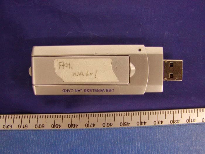
Click to zoom
Application Details
- Equipment Class
- DTS - Digital Transmission System
- Date of Grant
- Jul 03, 2004
- Application Purpose
- Original Equipment
- Date of Application
- Jul 03, 2004
- Equipment Note
- USB Wireless LAN Adapter
- Frequency Range
- 2412.00000000 - 2462.00000000
- Country
- China
Documents & Files
Document Text
Text extracted from the exhibit documents filed with the FCC. Open a document above to read the original.
Users Manual
USB Wireless LAN Adapter User Manual USB Wireless LAN Adapter 1 Content 1. Product Introduction............................................................................................2 2. USB Wireless LAN Adapter Installation.....................................................................4 3 Appendix..........................................................................................................18 USB Wireless LAN Adapter 2 1. Product Introduction Thank you for using USB WLAN product. This installation guide will help you install USB Wireless LAN Adapter and connect to the Internet quick & easy. Package Contents 1. USB Wireless LAN Adapter 2. Quick Installation Guide 3. Manual & Driver CD Disc 4. USB cable System Requirements 1. Desktop/ Laptop with USB port and CD-ROM driver 2. Operating System: Windows 98 SE/ME/2000/XP USB Wireless LAN Adapter 3 Applied Environments There are two application modes for this WLAN Adapter, the “Ad-Hoc mode” and the “Infrastructure mode”. (For further explain, please refer to the “WLAN Application Modes” below) Different modes require different settings. Please check the environment first. Infrastructure mode: Via “Access Point” (AP) to connect to the Internet. This mode further gives wireless access to Internet or data sharing under a previously wired environment. Figure1 Ad-Hoc mode: Connecting to other computer with WLAN Adapter. This mode does not need AP to connect to each other. USB Wireless LAN Adapter 4 Figure2 WLAN Application Modes Ad-Hoc Mode Ad-Hoc mode is a Peer-to-Peer mode. Without an AP, computers can also connect to each other by USB Wireless LAN Adapter. With this mode, computers are able to share data or connect to the Internet if one of them is already connected to. Infrastructure Mode Infrastructure mode including an AP, unlike Ad-Hoc mode, enabling users to best utilizes the frequency bandwidth of the AP. This mode enables users to integrate wired and wireless infrastructures. Through APs, wireless users are able to access wired resources, for example: Internet, database, and printers. Advantages Comparing to Ad-Hoc mode, Infrastructure mode has the following advantages: 9 Longer distance: Through AP, the wireless access distance is longer. 9 Roaming: The wireless devices can move within the AP support area. 9 Integration of wired and wireless environment. USB Wireless LAN Adapter 5 2. USB Wireless LAN Adapter Installation Note: The screens showed below are from Windows XP .For other Windows system, the steps are the same, but the screens shown will be a little different. After plugging USB Wireless LAN Adapter into your PC, it will automatically find and alert a New USB Device. , Then you do nothing ,our wireless lan Adapter will do all things,if your computer has a long time response ,you can click cancel ,it wil also help you do it . After successful installation, The software will automatically search for available APs for connecting to the Internet. Figure3 Here are two different utility to configure you wireless setting on XP, although we provide another choice, but in functional, both of them are similar. You can choose any one of them, which you more like or convenience to use. 1 Windows XP Wireless Network Connection Setting. 1. After finished install driver and utility on your system. Let’s starting to setup your wireless Adapter. First of all we will see the connection notice in the right corner Figure4 USB Wireless LAN Adapter 6 2. Click the notice frame and it will popup a setup dialog as below. If there have some efficient access point, which efficient range contains your pc Adapter range, then the SSID will show in the “Available networks” list. Select one and click the Connect button. Figure5 3 It’s normal sight when you pick a good connection. Windows XP will appear warning notice for a second. 4. After several seconds, you will see connection states information on notice frame. It will show SSID and signal strength. USB Wireless LAN Adapter 7 Figure6 2 Use Manufacturer’s Configuration Utility We provide another wireless setting utility for Windows use. In windows XP system, But you need to disable the Windows XP's wireless configuration USB Wireless LAN Adapter 8 Figure7 Click properties, Uncheck Use Windows to configure my wireless network settings Figure8 Then click OK Click the icon and the software utility window shows up. 1. Status window allows you to change Operation Mode, Channel, SSID, Tx Rate, Int Romaing, and Radio. It also shows the connecting signal and quality for you to adjust related infrastructures and configurations. USB Wireless LAN Adapter 9 Figure9 2. Statistics window: It shows the real time transmitting and receiving status. Figure10 3. Site Survey window: Click “Scan” to search all available WLAN devices and their status in current environment. Double click the device you want to connect. USB Wireless LAN Adapter 10 Figure11 4. Encryption window: USB Wireless LAN Adapter is able to provide 64/128Bit encryption. Figure12 USB Wireless LAN Adapter 11 5. Advanced window: It provides you to adjust PREAMBLE, Fragmentation Threshold, RTS/CTS Threshold, and Power Save function. Figure13 6. Profiles window: It provides customers to change settings and save them in the configuration file. USB Wireless LAN Adapter 12 Figure14 7. Info window: It shows the latest software version and MAC address. Figure15 USB Wireless LAN Adapter 13 Appendix 1. Operation Mode: USB Wireless Lan Adapter has two modes, ‘Infrastructure’ and ‘Ad-Hoc’. The default setting is “Infrastructure”. (Please refer to the Product Introduction ) 2 Channel: The channel setting should follow the regulation of the local government. For ‘Infrastructure’ mode, the channel does not need to be set. It will automatically change to the same channel as AP’s. In ‘Ad-Hoc’ mode, users can change the channel to match the connected computer. 3 SSID: When STA (WLAN Adapter) is in Ad-Hoc mode, all connecting STA should have the same SSID…
Text truncated - open the document above for the full version.
Block Diagram
ANT Regulator Regulator 2.4GHz Usb USB HUB AU9254 USB Port (PC Side) USB PORT Micro controller Reset Circuit (Built-in MCU) Power supply (Built-in MCU) LED Write protection N and flash 16~256MB AT M E L MAC&Base band AT76C505 BPF PA RF5189 Oscillator 12MHz EPPROM Switch RF TransceiverRF2958 SAW374MHZ SRAM
External Photos
EXHIBIT C - EUT EXTERNAL PHOTOGRAPHS EUT – Top View EUT – Bottom View EUT – Port Cover Removed View I EUT – Port Cover Removed View II
ID Label/Location Info
EXHIBIT A - FCC ID LABEL INFORMATION Proposed FCC ID Label Specifications : Text is black or white in color and is left justified. Labels are silk- screened and shall be “permanently affixed” at a conspicuous location on the EUT. Proposed Label Location on EUT Bottom Side of EUT/FCC ID Label FCC ID: I38-NA8300-001 This device complies with Part 15 o the FCC Rules. Operation is subject to the following two conditions: (1) this device may not cause harmful interference, and (2) this device must accept any interference received, including interference that may cause undesired operation. 2.1875" 1.0" FCC ID: P2DWA601
Internal Photos
EXHIBIT C - EUT INTERNAL PHOTOGRAPHS EUT – Housing and Board View Board – Component View Board – Solder View EUT – Cover and Antenna View Interface Board – Component View Interface Board – Solder View Transceiver Board – Component View Transceiver Board – Solder View
Operational Description
The WA601 circuit description: The usb flash disk controller AU9384 USB signal powered by the hub AU9254 that is an integrated single chip USB hub controller designed for the emerging industry-standard Universal Serial Bus (USB) . The AU9254 supports four USB downstream ports. Each downstream port has power switch control, and over-current sensing. The NO.1 downstream port connected the USB flash disk data signal D+ and d-, by right of this, The usb flash disk controller briged the flash memory and host USB bus. The NO.4 downstream port connected the wireless LAN dongle, In Schematic file,the j1 is wireless LAN dongle connector. From the PC HOST on carrying the copular USB BUS through two electric resistance for matchings R13, R15 links the USB HUB AU9254, among them HUB of next a the first port links the controller of UFD 6685, HUB of next a the fourth port links WIRELESS LAN module, descend a port match the electric resistance is a R16/17/11/12. USB HUB next an USB for the first with the fourth port linking DEVICE all from the power supply of USB BUS, the controller of UFD manages a NAND FLASH, such as:U3/ U4.( K9F6408/2808 ...) by the I/O BUS of the itself. The crystal oscillates the machine( Y1) work in the 12 MHZ, for the controller of UFD and standard clock in offering in HUB in USB signal. The transmitter of the EUT is powered by host equipment. The antenna used in this product is External antenna with URL connector. The other instruction, please have a look at the users manual. DSSS Information This device is Direct Sequence Spread Spectrum, the data is mixed by pseudorandom code which is an orthogonal code. The mixed data is digital modulated by BPSK and QPSK technique depends on the data rates. The CCK coding is applied for increasing the data rate, and also the processing gain will be increased. The bit rates are 1, 2, 5.5, 11Mbps, the symbol rates are 1, 1, 1.375, 1.375Mbps, and the chip rates are always 11Mbps. So, the Chip/symbol is 11, 11, 8 and 8 respectively. Although is higher bit rate, the processing gain is lower than 10, but the CCK coding used in higher bit rate will provide 2.2dB coding gain.
Schematics
nMOEnSCE MOSI M_D[0:7] M_A[0:16] USBATT DP MISO SPI_CLK DN S_DATASEL0S_CLK 22MHz nSPI_CS RADIO_PEdGSSEL1 nMWE RX_I+ DVGCTXVGC RX_Q+PAPERX_PE ANTSEL1ANTSEL0 RX_Q- RX_I- TX_Q+TX_I+ CCA GPIO4 GPIO5 GPIO6 GPIO7 GPIO2 GPIO1 GPIO0 LED TX_PE CFG0 CFG1 nTRST TCKTDO DVCC VCCS VCCS VCCS VCCS VCCS VCCS VCCS VCCS C111 100nF C115 2.2nF, 10% C105 2.2nF, 10% C158 100 nF R103 3.3K,NP R2043.3K C98 10 uF R33 10M C100 100nF C116 100nF U101 ComboUSB D3 A1 C2 B1E4 D2C1 E3 D1 F4F3 E1E2 G4 F1F2 G1G2G3 H2H1H3 J2J1J3 H4 K1 J4 K2 L1 K3 L2 K4 M1 L3 M2 J5 L4 M3 K5 M4 J6 K6 M5 L5 J7 M6 L6 M7 L7 K7 L8 M8 K8 L9 M9 K9 J8 M10 J9 L10 M11 K10 L11 B11C10B12C11D9C12E9D10D12D11E10E12E11F10F11F12G11G12F9H11H12G10G9J12H10K12J11H9L12K11M12J10 B2 C3 A2 B3 D4 A3 D5 C4 A4 B4 C5 A5 B5 C6 B6 A6 B7 A7 D6 B8 A8 C7 D7 A9 C8 A10 B9 D8 A11 B10 A12 C9 ntrst1tms1VCCGNDVCCacGNDacGNDDPDMSUSPGPIO3test_cktestselGNDLFTVCCXTAL1XTAL2GNDacspi_pcsMOSIMISOspi_clkVCCacGNDacMA19MA18MA17MA16MA15MA14MA13 MA12 MA11 MA10 VCC GND MA9 MA8 MA7 MA6 MA5 MA4 MA3 MA2 MA1 MA0 VCCac GNDac MD7 MD6 MD5 MD4 MD3 MD2 MD1 MD0 VCC GND VCCac GNDac cssr cspr nwrite avddac iref vref agnd1 vcx_ac tx_agc rx_agc rx_iprx_in avdd1 avddpy1 agndpy2 rx_qnrx_qp tx_iptx_in tx_qntx_qp agndcw1 GPIO0 RX_PE PA_PE TX_PE GNDac VCCac VCC GND GNDac reset GND nINTROMCONF nread TDO1 TDI1 TCK1 NC2 VCC USBattach GND GND VCC GNDac VCCac GPIO4 GPIO5 GPIO6 GPIO7 SYNTHCLK SYNTHDATA CCA LNAGAIN ANT1 ANT0 SEL1 SEL0 GND VCC RADIO_PE GPIO2 GPIO1 NC1 VCC ULFT GND R104 3.3K, C110 100nF R102 3.3KNP R100 150 , 5% C165 10nF, 10% R32 100 C114 100nF R2000 C112 100nF R105 0 C104 10nF, 10% R18 150 , 5% R101 3k3 C102 100nF C99100 nF nMWEnMOE M_D[0:7] nSCE M_A[0:16] MOSI nSPI_CS MISO SPI_CLK nSPI_CSMOSI SPI_CLK MISO VCCS VCCS VCCS C118100nF C216100nF U26IS63LV1024 G5H6H5H4H3H2H1A6B3 D6 B5A5C4B4A4B2A2G4 D1 G1 F1 C1 B1E1 G6 F6 C6 B6 G2 E6 G3A1F4F3 A15A14A13A12A11A10 A9A8 WE VCC2 A7A6A5A4A3A2A1 A16 GNDI/O7I/O6I/O5I/O4VCCI/O3I/O2I/O1I/O0 OE GND2 CE A0 A17A18 R1203.3k U109 AT45DB 011-XC 1234567 891011121314 RDY/BUSY RESETWPVCCGNDSCKSO SI NCNCNCNCNC CS U14 MAP-8Y1_P0.65_W4.9_L3.0 5 3142 678 SI nWPnCSGNDSO SCK nHOLD VCC RX_Q RX_Q+ RX_I+ TX_Q+ TX_I+ TX_ITX_Q DVGC RX_VGC MCLK22MHz SEL1 SDI SPI_CLK SCLKSSB RX_I RX_Q- RX_I- LNA_GS RX_PE 1V7REF dGS V MOSI VCC VCOSC VCCS R65NP R15 100 C23NP R510 R531K C2968pF.NP R951K C22NP R77 39k U1122MHz. F338/20 ppm 12 43 E/DGND Vcc Out C183220nF C107 22pF R63 150K C3027pF.NP U106TC7SL08 NP 123 45 IN1IN2gnd out vcc -+ U107LMV-821 13 4 52 C28NP C166100nF NP C71220nF R8 0.NP R10 0 R179 0 R69 0 R16 O .NP C132100nF R93 1K R13 0 R941K C177pF R76100k C1022pF R6647 C1067pF R626.2K R35330 R210R410 R68 0 R6710 R910 R140 .NP R58NP C1822pF C19 10nF 55 44 33 22 11 D D C C B B A A of RX_PETX_PEMCLKRX_VGCRX_IRX_QTX_ITX_QLNA_GSSDISSBSCLK 1V7REF VCC VCC VCC VCC VCC VCCPA VCC VCC C1NP C216.2pF C356.2pF L4 56nH R6NP C4 10nF C4722pF C11 6.2pF L612nH C469.1pF C810nF L7 BLM11HA471 C3NP C1510nF C426.2pF C5 330pF C26.2pF C36 10nF C2010nF U8RF2958 1 2 3 4 5 6 7 8 9 10111213141516 3231302928272625 24 23 22 21 20 19 18 17 33 IF IN+ IF IN- VCC IF R BIAS VCC RF2 VCC RF1 IF OUT- IF OUT+ TX VGCRF OUTVCC RF3RF INLNA GSVCC PLL1DIG REGMODE1 RX VGC RX I RX Q VCC BB TX I I BYP TX Q Q BYP VREF PLL REG VCC PLL4 SCLK SSB SDI MCLK MODE0 GND FL2BPF 2.45GHz 1 2 4 5 3 IN OUT GND GND GND R11 0 R1 22.1K, 1% C399.1pF C27 10nF C9 6.2pF C43 NP C710nF C4412pF L2 15nH C4512pF U2 RF5189 123 4 5 6 789 10 11 12 13 RF_INVREG1_GNDSGND VREG1 VREG2 VREG2_GND PWR_SN RF_OUTRF_OUT VCC1 VCC1 VCC2 GND C256.2pF R12 0 L556nH C4110nF J2CL331-0471-0-01 1 23 IN GND1GND2 C31 NP R7NP L3 15nH C40 6.2pF C6 330pF C13 6.2pF U6AS179-92 13 465 2 TXRX /RXEN RXEN ANT GND C261uF FL1 SAW 374MHz 12 4 5 3 67 8 GNDIN- GND GND IN+ OUT- OUT+ GND of LED V DVCC VCCS VCCS VCCPA VCOSC VCC +5V L20Ferrite BEAD C48 10nF C173 100nF C16 1nF C931uF R1760 R172 0 Q13 2SC5658 1 32 R178 1K C24 100nF C101 4.7uF R3 0NP L85Ferrite BEAD R174 0 D2 led_0603 12 L103Ferrite BEAD C122 10nF C184 100nF U19AME8801CEEV 1 5 32 4 Input Output ON-/OFFGND BYP C127 4.7uF C123 4.7uF,NP C12 2.2uF C322.2uF R1843.3K, 5% U17 AME-8805.33 2 1 3 Vin GND Vout R1140 R177 330, 5% L8 Ferrite BEAD DP USBATT DN +5V VCCS L42 C174 4.7uF C177 220pF U15 A PLUG USB CONN. 4 23 1 GND D- D+ VCC R182 24 L41 R180 24 R36 1.5K R1810. NP C176 100nF C178 220pF 55 44 33 22 11 D D C C B B A A PAPESEL1RX_Q-dVGCRADIO_PEANTSEL1ANTSEL0RX_I+RX_PERX_Q+TXVGCTX_PESEL0dGSRX_I-SPI_CLKMOSInSPI_CSMISOS_DATARX_VGCLNA_GSCCASCLKTX_QTX_I LED GPIO0GPIO1GPIO2 GPIO4 GPIO5GPIO6GPIO7 TCKCFG0CFG1 TDO nTRST RX_IRX_QS_CLK DVCC VCCPA VCC VCCS VCCPA RX_I ANTSEL1 VCCS CFG0 S_DATASEL0 GPIO7 TCK TX_PE nTRST PAPEMISO TX_I GPIO1 VCCP TX_Q dGSRX_I-dVGC GND_A TXVGCRX_I+RADIO_PEMOSI RX_Q LNA_GS GPIO5 SEL1 VCC RX_PE GPIO4 TDOCFG1 GPIO2GPIO6 VDD DGND GPIO3 GPIO0 SPI_CLKSCLKS_CLKRX_Q-ANTSEL0nSPI_CSRX_VGC VCCPA RX_Q+CCA
Test Report
Note: This test report is specially limited to the above client company and product model only. It may not be duplicated without prior written consent of Bay Area Compliance Laboratory Corporation. This report must not be used by the client to claim product endorsement by NVLAP or any agency of the U.S. Government. FCC PART 15.247 EMI MEASUREMENT AND TEST REPORT For FU KUANG HUI ELECTRONICS CO., LTD.(SHEN ZHEN) The second Industrial Park of Xia Village, Gongming Baoan District, Shenzhen City, Guongdong Province, China FCC ID: P2DWA601 This Report Concerns: Original Report Equipment Type: Transceiver - USB Wireless LAN Adapter Test Engineer: Ming Jing / Report No.: R0405114 Report Date: 2004-05-25 Reviewed By: Ling Zhang / Prepared By: Bay Area Compliance Laboratory Corporation (BACL) 230 Commercial Street Sunnyvale, CA 94085 Tel: (408) 732-9162 Fax: (408) 732 9164 FU KUANG HUI ELECTRONICS CO., LTD.(SHEN ZHEN) FCC ID: P2DWA601 Report # R0405114Rpt.doc Page 2 of 32 FCC Part 15.247 Test Report TABLE OF CONTENTS GENERAL INFORMATION.......................................................................................................................................4 PRODUCT DESCRIPTION FOR EQUIPMENT UNDER TEST (EUT) ....................................................................................4 OBJECTIVE...................................................................................................................................................................4 RELATED SUBMITTAL(S)/GRANT(S).............................................................................................................................4 TEST METHODOLOGY..................................................................................................................................................4 TEST FACILITY.............................................................................................................................................................4 SYSTEM TEST CONFIGURATION ..........................................................................................................................6 JUSTIFICATION.............................................................................................................................................................6 EUT EXERCISE SOFTWARE..........................................................................................................................................6 SPECIAL ACCESSORIES.................................................................................................................................................6 SCHEMATICS / BLOCK DIAGRAM.................................................................................................................................6 EQUIPMENT MODIFICATIONS.......................................................................................................................................6 CONFIGURATION OF TEST SYSTEM..............................................................................................................................7 TEST SETUP BLOCK DIAGRAM.....................................................................................................................................7 SUPPORT EQUIPMENT LIST AND DETAILS....................................................................................................................8 EXTERNAL I/O CABLING LIST AND DETAILS...............................................................................................................8 SUMMARY OF TEST RESULTS ...............................................................................................................................9 §15.203 - ANTENNA REQUIREMENT....................................................................................................................10 STANDARD APPLICABLE............................................................................................................................................10 §15.207(A) - CONDUCTED EMISSIONS.................................................................................................................11 MEASUREMENT UNCERTAINTY..................................................................................................................................11 EUT SETUP................................................................................................................................................................11 SPECTRUM ANALYZER SETUP....................................................................................................................................11 TEST EQUIPMENT LIST AND DETAILS.........................................................................................................................11 TEST PROCEDURE......................................................................................................................................................11 SUMMARY OF TEST RESULTS.....................................................................................................................................12 CONDUCTED EMISSIONS TEST DATA.........................................................................................................................12 PLOT OF CONDUCTED EMISSIONS TEST DATA...........................................................................................................12 §15.209(A) - SPURIOUS EMISSION ........................................................................................................................15 STANDARD APPLICABLE............................................................................................................................................15 MEASUREMENT PROCEDURE......................................................................................................................................15 EQUIPMENT LISTS...................................................................…
Text truncated - open the document above for the full version.
Test Setup Photos
EXHIBIT B - TEST SETUP PHOTOGRAPHS Conducted Emission - Front View Conducted Emission - Side View Radiated Emission - Front View Radiated Emission - Rear View Antenna Location Antenna Location Antenna Location Antenna Location
Contact Information
Applicant
Lin Wen Long(PCC Supervisor)
Test Firm
Bay Area Compliance LaboratoryJohn Chan
Technical Specifications
| # | Rule Parts | Frequency Range | Power Output |
|---|---|---|---|
| 1 | 15C | 2.41 GHz - 2.46 GHz | 15.90 mW |
Other Applications from Fu Kuang Hui Electronics Co., Ltd (Shenzhen)
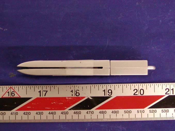
P2DBTU97
Oct 30, 2003UFD+Bluetooth
Equipment Class
DSS - Part 15 Spread Spectrum Transmitter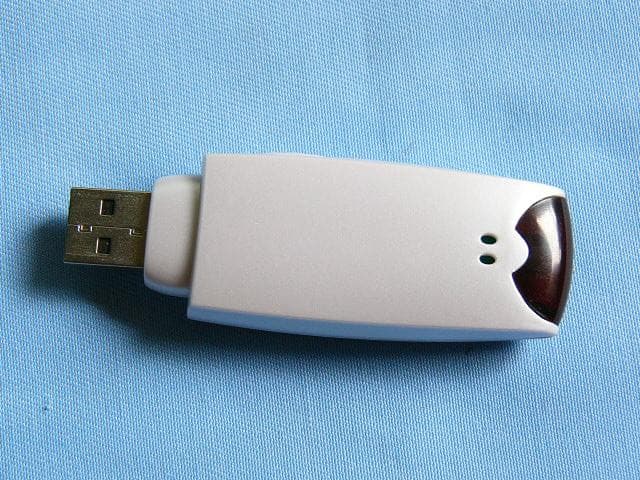
P2DBTU9X
Sep 28, 2003UFD + Bluetooth
Equipment Class
DSS - Part 15 Spread Spectrum Transmitter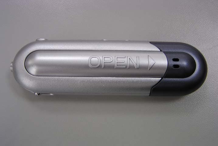
P2DMP309
Apr 23, 2003Digital Media Player
Equipment Class
JBP - Part 15 Class B Computing Device Peripheral
P2DMP308
Apr 23, 2003Digital Media Player
Equipment Class
JBP - Part 15 Class B Computing Device Peripheral
P2DMP307
Apr 23, 2003Digital Media Player
Equipment Class
JBP - Part 15 Class B Computing Device Peripheral