P35SSG-819-1W2WCellular and PCS Band Full Duplex Amplifier
Arrista Technologies Inc.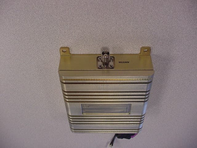
Click to zoom
Application Details
- Equipment Class
- AMP - Amplifier
- Date of Grant
- Jan 06, 2003
- Application Purpose
- Original Equipment
- Date of Application
- Oct 22, 2002
- Equipment Note
- Cellular and PCS Band Full Duplex Amplifier
- Frequency Range
- 1850.00000000 - 1910.00000000
- Company
- Arrista Technologies Inc.
- Country
- Canada
Documents & Files
Document Text
Text extracted from the exhibit documents filed with the FCC. Open a document above to read the original.
Users Manual
SG8-19 Signal Amplifier Installation Manual Page 1 of 2 Copyright 2002, Arrista Technologies, Inc., All rights reserved. Rev C D00000413 Made in North America Note: Before installing the SG8-19 Signal Amplifier, please read the entire contents of this manual. Parts List Item Qty Description 1 1 SG8-19 Signal Amplifier 2 1 1.5 Meter (59”) RF Cable 3 1 2 Meter (78”) DC Power Cable Tools and Other Materials Required Item Description 1 Electric drill (as required for signal amplifier mounting holes) 2 Screw driver 3 Qty 4 screws (length and type as required for signal amplifier mounting) 4 Wire cutters / strippers 5 Qty 2 wire connection insulators or insulating material (as required for DC power cable connection to 12V DC system) WARNINGS! ∇ Directly wired vehicle antennas, mounted a minimum distance of 50 cm (19.5”) away from any person, are recommended. ∇ Ensure that the external antenna connected to the SG8-19 amplifier is mounted at least 0.5 meters away from any seating position in the automobile to ensure that the FCC Maximum Possible Exposure (MPE) guidelines are satisfied. At a distance of 0.5 meter from the externally mounted 3dBi antenna connected to the SG800, the uncontrolled MPE power density will be 0.13mW/cm 2 (FCC guideline 0.55mW/ cm 2 ). ∇ Mounting a signal amplifier in the engine cavity or on the underside of the vehicle will void the manufacturer’s warranty. ∇ Subjecting the amplifier to voltages greater than 30 Volts DC will damage the amplifier and void the manufacturers warranty. ∇ Any vehicle with an electrical system of greater than 30 Volts DC should use a step-down voltage regulator to bring the voltage within the DC operating power range of the amplifier (10 to 30V dc). ∇ Under no circumstances should the amplifier be powered up without a properly connected 50 ohm 800 MHz cellular antenna or the amplifier may be damaged, resulting in the manufacturer’ warranty being void. ∇ For optimum performance and compatibility with cellular service provider requirements, it is recommended that an external antenna with a maximum gain of 3dBi be installed. ∇ Use of cellular amplifiers with antennas of higher gains than 3 dBi gain is in violation of FCC regulations for which the offender will be fully liable, and warranty claims will be voided. It is recommended that only certified automotive installation technicians install this product in a vehicle. Installation by any other person is at the risk of the vehicle owner and operator. Installation Selecting a Suitable Location To Mount The Signal Amplifier Locate a suitable place to mount and conceal the signal amplifier. Suggested mounting locations include: under the dashboard, under the seat, or in the trunk. For peak performance the signal amplifier should be mounted as close to the phone handset as SG8-19 Signal Amplifier Installation Manual Page 2 of 2 Copyright 2002, Arrista Technologies, Inc., All rights reserved. Rev C D00000413 Made in North America possible. The amplifier’s location should be easily accessible and mounted away from moving parts, as well as excessive heat and moisture. Installation Cautions ∇ Use caution to avoid drilling through or near fuel lines or fuel tanks; brake lines; or electrical wiring. ∇ Do not mount the signal amplifier or its associated wiring in a location that may interfere with the safe operation of the vehicle. Installation Of The Signal Amplifier SignalAmplifier 1.5 M Cable Color/Black Black (12 V DC) Antenna* 1 Antenna Cable* 1 * 1 Optional items must be purchased separately. Phone/Cradle or RF output device* 1 1 2 3 SignalAmplifier 1.5 M Cable Color/Black Black (12 V DC) Antenna* 1 Antenna Cable* 1 * 1 Optional items must be purchased separately. Phone/Cradle or RF output device* 1 1 2 3 Typical Installation For Under The Seat Mounting 1. For safety, disconnect the vehicle’s negative “−“ battery terminal to remove power from the vehicle. 2. Drill holes and mount the signal amplifier (ITEM 1) in the selected location. 3. Connect the colored striped black wire of the supplied 2 Meter (78”) power cable (ITEM 3) for the signal amplifier to a positive connection on the vehicle’s electrical system. Choose a 10 to 30 Volt DC circuit that is: fuse protected; and ignition switched. (Often referred to as the “Accessory output”) 4. Attach the solid black wire of the supplied 2 Meter (78”) power cable (ITEM 3) to a vehicle electrical ground point. 5. Attach one end of the antenna cable* 1 to the 3dB antenna. The other end is connected to the cellular phone handset via a cradle or an RF output cable *1 to the signal amplifier’s ANTENNA output connector. 6. Connect the amplifier’s PHONE input connector to the cellular phone handset via a cradle or an RF output cable using the provided 1.5 Meter (59”) RF cable (ITEM 2). 7. Reconnect the vehicle’s negative “−“ Battery terminal. Limited Warranty Arrista Technologies Inc. warrants that this product is free from any defects in material or workmanship for a period of one year. If a defect in material or workmanship is found, Arrista Technologies Inc. agrees to repair or replace the product at its own discretion, free of charge to the original purchaser. Please return the product along with proof of purchase to the original authorized dealer. This warranty is null and void if the product has been modified, abused, tampered with, subjected to abnormal conditions, or transferred to someone other than the original purchaser. All brands and trademarks are the property of their respective owners. Designed and manufactured in North America Use a 3dB antenna for Optimal Performance
Users Manual
SA200 Signal Amplifier Installation Manual Note: Before installing the SA200 Signal Amplifier, please read the entire contents of this manual. Parts List Item Description 1 SA200 Signal Amplifier. 1 2 1.5 meter (59”) RF cable. 2 3 2 meter (78”) power cable. 3 4 Connector adapter FME female to TNC male. 4 5 Connector adapter FME male to TNC male. 5 6 Cellular telephone / Cradle or RF Output Device. (Optional item purchased separately) 6 7 Antenna Cable. (Optional item purchased separately) 7 8 Antenna. (Use 3 dB antenna for optimal performance) (Optional item purchased separately) 8 SA200 Dual Band Cellular Amplifier 1 2 3 45 Tools and Other Materials Required Item Description 1 Electric drill (as required for signal amplifier mounting holes). 2 Screw driver. 3 Qty 4 screws (length and type as required for signal amplifier mounting). 4 Wire cutters / strippers. 5 Qty 2 wire connection insulators or insulating material (as required for power cable connection to 12V system). WARNINGS! ∇ NOTICE: During transmitter operation, a minimum distance of 50cm (20 in.) shall be maintained between the antenna and personnel, in order to meet the maximum permissible exposure (MPE) limits in section 1.1310 of FCC Rules. ∇ ∇ Mounting a signal amplifier in the engine cavity or on the underside of the vehicle will void the manufacturer’s warranty. ∇ ∇ Subjecting the amplifier to voltages greater than 30V will damage the amplifier and void the manufacturer’s warranty. ∇ ∇ Any vehicle with an electrical system of greater than 30V should use a step-down voltage regulator to bring the voltage within the operating power range of the amplifier (10-30V). ∇ ∇ Under no circumstances should the amplifier be powered up without a properly connected 50 ohm 800/1900 MHz cellular antenna or the amplifier may be damaged, resulting in the manufacturer’s warranty being void. ∇ ∇ For optimum performance and compatibility with cellular service provider requirements, it is recommended that an external antenna with a maximum gain of 3dB be installed. ∇ ∇ Use of cellular amplifiers with antennas of higher gains than 5 dBd gain is in violation of FCC regulations for which the offender will be fully liable, and warranty claims will be voided. ∇ It is recommended that only certified automotive installation technicians install this product in a vehicle. Installation by any other person is at the risk of the vehicle owner and operator. Rev A D00050652 Made in North America Page 1 of 1 Rev A D00050652 Page 1 of 1 SA200 Signal Amplifier Installation Manual Installation Selecting a Suitable Location to Mount the Signal Amplifier Locate a suitable place to mount and conceal the signal amplifier. Suggested mounting locations include: under the dashboard, under the seat, or in the trunk. For peak performance the signal amplifier should be installed using the supplied cabling and connectors. The amplifier should be mounted away from moving parts, as well as excessive heat and/or moisture. Installation Cautions ∇ Use caution to avoid drilling through or near fuel lines or fuel tanks; brake lines; or electrical wiring. ∇ ∇ Do not mount the signal amplifier or its associated wiring in a location that may interfere with the safe operation of the vehicle. ∇ Installation Of The Signal Amplifier 1 + 3 _ 12V DC 2 6 7 8 Typical Installation For Under The Seat Mounting 1. For safety, disconnect the vehicle’s negative (− ) battery terminal to remove power from the vehicle. 1. 2. Drill holes and mount the signal amplifier 1 in the selected location. 2. 3. Connect the white-striped black wire of the supplied 2-meter (78”) power cable 3 to a positive connection on the vehicle’s electrical system. Choose a 10-30V circuit that is fuse protected and ignition switched. (Often referred to as the “Accessory Output”) 3. 4. Attach the solid black wire of the supplied 2-metre (78”) power cable 3 to a vehicle electrical ground point. 4. 5. Connect the amplifier’s ANTENNA( ) connector to the 3dB antenna using the provided antenna cable 7 and adapter 4 or 5 if necessary. 5. 6. Connect the amplifier’s PHONE() connector to the cellular phone handset via a cradle using the provided 1.5 Meter (59”) RF cable 2 and adapter 4 or 5 if necessary. 6. 7. Reconnect the vehicle’s negative (− ) Battery terminal. 7. Limited Warranty The SA200 Signal Amplifier is warranted free from any defects in material or workmanship for a period of one year. If a defect in material or workmanship is found, the product will be repaired or replaced at the discretion of the manufacturer, free of charge to the original purchaser. Please return the product along with proof of purchase to the original point of purchase. This warranty is null and void if the product has been modified, abused, tampered with, subjected to abnormal conditions, or transferred to someone other than the original purchaser. All brands and trademarks are the property of their respective owners. Rev A D00050652 Made in North America Page 2 of 2 Rev A D00050652 Page 2 of 2
Cover Letter(s)
_______________________________________________________________________ Confidential Page 1 October 25, 2002 5-55 Henlow Bay, Winnipeg, Manitoba, R3Y 1G4 Phone: 204-489-3200 Fax: 204-489-8300 October 25, 2002 Exhibit of Confidentiality To Whom It May Concern: Arrista Technologies would like the following submitted exhibits treated as confidential material: 1. Amplifier Schematic 2. Block Diagram Amplifier 3. Amplifier Parts Listing 4. Operational Description The amplifier design, specifically, the gain control circuitry is of novel design and a US patent has been filed on it. As there is no other amplifier design that incorporates the gain control function the way the SG8-19 does, we believe that we have a competitive advantage over competing designs out in the market place. Roman Wroczynski Director of Product Development Arrista Technologies Inc Tel: (204) 489-3200 Fax: (204) 489-8300 [email protected]
External Photos
________________________________________________________________________ Confidential Page 1 October 28, 2002 5-55 Henlow Bay, Winnipeg, Manitoba R3Y 1G4 Phone: 204-489-3200 Fax: 204-489-8300 SG8-19 External Photos
ID Label/Location Info
C00000 A LABEL, FCC WARNING Sheet 1 of 1 C00000 020130SRC NOTES: 1. LABEL SPECIFICATIONS: LABEL STOCK: 3M TAMPER-INDICATING LABEL MATERIAL FOR THERMAL TRANSFER PRINTING 7866. FACE STOCK: 2.0 MIL GLOSS WHITE POLYESTER DESTRUCT PATTERN: "VOID" ADHESIVE: 1.0 MIL #300 "HI-STRENGTH" ACRYLIC LINER: 3.2 MIL55# DENSIFIED KRAFT SCALE: NTS Caution: This product is designed to be used with an external antenna with maximum gain of 3 dBi or less. The use of an antenna of higher gain is strictly prohibited and violates FCC regulations. 8 point Helvetica, Bold 6 point Helvetica FCC ID: P35SSG-819-1W2W Made In Canada 6 point Helvetica Patent Pending 8 point Helvetica 6 point Helvetica 2.25 1.00
ID Label/Location Info
FCC Label Location Photo The following picture shows a label mounted to the bottom of the amplifier casing. We have used a label that was placed on an earlier revision of this product to demonstrate positioning. The amplifier will use the label specifications that has been submitted in an earlier document, and will be placed according to this photo.
Internal Photos
________________________________________________________________________ Confidential Page 1 October 28, 2002 5-55 Henlow Bay, Winnipeg, Manitoba R3Y 1G4 Phone: 204-489-3200 Fax: 204-489-8300 SG8-19 Internal Pictures
RF Exposure Info
________________________________________________________________________ Confidential Page 1 October 18, 2002 5-55 Henlow Bay, Winnipeg, Manitoba R3Y 1G4 Phone: 204-489-3200 Fax: 204-489-8300 RF Human Exposure Analysis Users may be concerned with the power levels achieved using booster amplifiers in-line with the handset, cradle and automobile antenna. The far field on-axis power flux density (W/m 2 ) is calculated using the following formula: S = G P T / 4πR 2 , Where: G = Numerical gain of the antenna P T = Power delivered to the antenna in watts R = Distance from the antenna in meters The following table shows the maximum output power of the booster amplifier combined with an antenna with 3dBi gain. This is the maximum antenna gain permissible as documented in the user/installation manual. The resulting radiated power density is compared to MPE limits for both uncontrolled and controlled environments. ________________________________________________________________________ Confidential Page 2 October 18, 2002 5-55 Henlow Bay, Winnipeg, Manitoba R3Y 1G4 Phone: 204-489-3200 Fax: 204-489-8300 Cellular Band (824-849MHz) Table 1. Cellular Band MPE Calculations Output power of the amplifier: 2W maximum Antenna Gain: Maximum antenna gain allowed as described in user/installation manual. 3dBi Operational Frequency: 824-849MHz Minimum distance (Controlled): From radiating source for personnel aware of radiofrequency equipment and who are able to limit their exposure time. (Installation Technicians) 0.5m Antenna mounted on vehicle exterior Minimum distance (Uncontrolled): From radiating source for personnel unaware of radiofrequency equipment and who are not able to limit their exposure time. (General Public) 0.5m Antenna mounted on vehicle exterior Estimated RF Power Density: 0.127mW/cm 2 Maximum Permissible Exposure (MPE): Controlled 6 min avg exposure 2.75mW/cm 2 Uncontrolled 30 min avg exposure 0.55mW/ cm 2 Complies with MPE Limits Yes Yes ________________________________________________________________________ Confidential Page 3 October 18, 2002 5-55 Henlow Bay, Winnipeg, Manitoba R3Y 1G4 Phone: 204-489-3200 Fax: 204-489-8300 PCS Band (1850-1910MHz) Table 2. PCS Band MPE Calculations Output power of the amplifier: 1W maximum Antenna Gain: Maximum antenna gain allowed as described in user/installation manual. 3dBi Operational Frequency: 1850-1910MHz Minimum distance (Controlled): From radiating source for personnel aware of radiofrequency equipment and who are able to limit their exposure time. (Installation Technicians) 0.5m Antenna mounted on vehicle exterior Minimum distance (Uncontrolled): From radiating source for personnel unaware of radiofrequency equipment and who are not able to limit their exposure time. (General Public) 0.5m Antenna mounted on vehicle exterior Estimated RF Power Density: 0.064 mW/cm 2 Maximum Permissible Exposure (MPE): Controlled 6 min avg exposure 5 mW/cm 2 Uncontrolled 30 min avg exposure 1 mW/ cm 2 Complies with MPE Limits Yes Yes
RF Exposure Info
FCC PART 1.1310 REPORT NO.: ATMPE00001 RF Human Exposure Analysis as per 47CFR§1.1310 1. Guidelines For transmitters operating in the 824-849 MHz range, paragraph 1.1310 Table 1 limits maximum permissible exposure (MPE) to f/1500 mW/cm 2 for uncontrolled environments and f/300 mW/cm 2 for controlled environments. For transmitters operating in the 1850-1910 MHz range, paragraph 1.1310 Table 1 limits maximum permissible exposure (MPE) to 1 mW/cm 2 for uncontrolled environments and 5 mW/cm 2 for controlled environments. The far field on-axis power flux density (W/m 2 ) is calculated using the following formula: S = G P T / 4πR 2 (1) Where: S = Power density (in appropriate units, e.g. mW/cm 2 ) G = Power gain of the antenna in the direction of interest relative to an isotropic radiator P T = Power input to the antenna (in appropriate units, e.g., mW) R = Distance to the center of radiation of the antenna (appropriate units, e.g., cm) It is important to note that the power gain factor, G, in Equation (1) is normally numeric gain. Therefore, when power gain is expressed in logarithmic terms, i.e., dB, a conversion is required using the relation: G=10^(dB/10) For example, a logarithmic power gain of 14 dB is equal to a numeric gain of 25.12. 2. SA200 Cellular Signal Amplifier Particulars The following table shows the maximum output power of the signal amplifier combined with an antenna with 3dBi gain. This is the maximum antenna gain permissible as documented in the user/installation manual. The resulting radiated power density is compared to MPE limits for both uncontrolled and controlled environments. Company: Arrista Technologies Inc. Equipment: SA200 Cellular Signal Amplifier Page 1 Copyright 2000 Arrista Technologies Inc. This document contains confidential information. FCC PART 1.1310 REPORT NO.: ATMPE00001 3. Cellular Band (824-849MHz) Table 1. Cellular Band MPE Calculations Output power of the amplifier: 1.36 W maximum Antenna Gain: Maximum antenna gain allowed as described in user/installation manual. 3dBi Operational Frequency: 824-849MHz Minimum distance (Controlled): From radiating source for personnel aware of radiofrequency equipment and who are able to limit their exposure time. (Installation Technicians) 50cm Antenna mounted on vehicle exterior Minimum distance (Uncontrolled): From radiating source for personnel unaware of radiofrequency equipment and who are not able to limit their exposure time. (General Public) 50cm Antenna mounted on vehicle exterior Calculated RF Power Density: 0.0864 mW/cm 2 Maximum Permissible Exposure (MPE): Controlled 6 min avg exposure 2.75mW/cm 2 Uncontrolled 30 min avg exposure 0.55mW/ cm 2 Complies with MPE Limits Yes Yes 4. Calculations S = G P T / 4πR 2 (1) S = (1.995 * 1.36*10³)/(4π*50 2 ) S = 2713/(10000π) S = 0.0864 mW/cm 2 Company: Arrista Technologies Inc. Equipment: SA200 Cellular Signal Amplifier Page 2 Copyright 2000 Arrista Technologies Inc. This document contains confidential information. FCC PART 1.1310 REPORT NO.: ATMPE00001 5. PCS Band (1850-1910MHz) Table 2. PCS Band MPE Calculations Output power of the amplifier: 1.00 W maximum Antenna Gain: Maximum antenna gain allowed as described in user/installation manual. 3dBi Operational Frequency: 1850-1910MHz Minimum distance (Controlled): From radiating source for personnel aware of radiofrequency equipment and who are able to limit their exposure time. (Installation Technicians) 0.5m Antenna mounted on vehicle exterior Minimum distance (Uncontrolled): From radiating source for personnel unaware of radiofrequency equipment and who are not able to limit their exposure time. (General Public) 0.5m Antenna mounted on vehicle exterior Calculated RF Power Density: 0.064 mW/cm 2 Maximum Permissible Exposure (MPE): Controlled 6 min avg exposure 5 mW/cm 2 Uncontrolled 30 min avg exposure 1 mW/ cm 2 Complies with MPE Limits Yes Yes 6. Calculations S = G P T / 4πR 2 , (1) S = (1.995 * 1.00*10³)/(4π*50 2 ) S = 1995/(10000π) S = 0.0635 mW/cm 2 The following instructions will be placed in the User/Installation Manual instructing installers and users to maintain the minimum MPE distances during operation of the EUT: "NOTICE: During transmitter operation, a minimum distance of 50cm (20 in.) shall be maintained between the antenna and personnel, in order to meet the maximum permissible exposure (MPE) limits in section 1.1310 of FCC Rules." Company: Arrista Technologies Inc. Equipment: SA200 Cellular Signal Amplifier Page 3 Copyright 2000 Arrista Technologies Inc. This document contains confidential information.
Test Report
Test Report: ATEMC000025 Applicant: Arrista Technologies Inc. 5-55 Henlow Bay Winnipeg, MB, CA R3Y 1G4 Equipment Under Test (EUT): AMPS / PCS / TDMA / CDMA Cellular Signal Amplifier MODEL: AT498 FCC ID: IN ACCORDANCE WITH: FCC PART 22, SUBPART H; FCC PART 24, SUBPART E CELLULAR BAND REPEATERS FCC PART 22, SUBPART H CELLULAR BAND REPEATERS REPORT NO.: ATEMC000025 Applicant: Arrista Technologies Inc. Equipment: AT498 Cellular Signal Amplifier Copyright 2000 Arrista Technologies Inc. This document contains confidential information. Page i FCC PART 22, SUBPART H CELLULAR BAND REPEATERS REPORT NO.: ATEMC000025 Applicant: Arrista Technologies Inc. T EST LAB PERSONNEL: Test Performed by: Date Signature Paul Eberling, CNA August 8, 2002 Brent Griffiths August 8, 2002 All information contained in and/or disclosed in this document is considered confidential information of Arrista Technologies Incorporated. Reproduction and distribution of this document in whole or part is strictly prohibited without the written consent of Arrista Technologies Incorporated. A PPROVALS: Date Name Title Signature October 21, 2002 Roman Wroczynski Director Development & Test Equipment: AT498 Cellular Signal Amplifier Copyright 2000 Arrista Technologies Inc. This document contains confidential information. Page ii FCC PART 22, SUBPART H CELLULAR BAND REPEATERS REPORT NO.: ATEMC000025 Applicant: Arrista Technologies Inc. Table of Contents 1. General Information.....................................................................................................6 1.1. Purpose................................................................................................................6 1.2. Test Methodology.................................................................................................6 1.3. Test Equipment list...............................................................................................6 1.4. Equipment Under Test Description.......................................................................7 1.5. General Equipment Specification..........................................................................7 1.5.1. Power Supply Specifications..........................................................................7 1.5.2. Transmitter (800 MHz Band)..........................................................................8 1.5.3. Receiver (800 MHz Band)..............................................................................8 1.5.4. Transmitter (1900 MHz Band)........................................................................8 1.5.5. Receiver (1900 MHz Band)............................................................................8 1.5.6. EUT Functional Block Diagram......................................................................9 1.6. Test Result Summary.........................................................................................10 1.7. Deviations...........................................................................................................10 1.8. Test Schedule Description..................................................................................10 1.8.1. RF Power Output.........................................................................................11 1.8.2. Emissions limitation & Occupied Bandwidth................................................11 1.8.3. Conducted Spurious Emissions at Antenna Terminals................................11 1.8.4. Radiated Field Strength of Spurious Emissions...........................................11 1.9. Test Facilities Description...................................................................................11 1.9.1. Internal Facilities..........................................................................................11 1.9.2. Radiated Emissions Test Site......................................................................11 2. Test Results...............................................................................................................13 2.1. RF Power Output................................................................................................13 2.1.1. SPECIFICATION REQUIREMENT:.............................................................13 2.1.2. MEASUREMENT PROCEDURE:................................................................13 2.1.3. TEST RESULTS:.........................................................................................13 2.1.4. MEASUREMENT DATA:.............................................................................13 2.1.5. Plot Data......................................................................................................15 2.2. Emissions Limitations For Cellular......................................................................19 2.2.1. SPECIFICATION REQUIREMENT:.............................................................19 2.2.2. MEASUREMENT PROCEDURE:................................................................19 2.2.3. TEST RESULTS:.........................................................................................20 2.2.4. MEASUREMENT DATA:.............................................................................20 2.3. Emissions Limitations For Cellular CDMA........................................................... 21 2.3.1. SPECIFICATION REQUIREMENT:.............................................................21 2.3.2. MEASUREMENT PROCEDURE:................................................................21 2.3.3. TEST RESULTS:.........................................................................................22 Equipment: AT498 Cellular Signal Amplifier Copyright 2000 Arrista Technologies Inc. This document contains confidential information. Page iii FCC PART 22, SUBPART H CELLULAR BAND REPEATERS REPORT NO.: ATEMC000025 Applicant: Arrista Technologies Inc. 2.3.4. MEASUREMENT DATA:.............................................................................22 2.4. CDMA Occupied Bandwidth …
Text truncated - open the document above for the full version.
Contact Information
Applicant
Roman Wroczynski(Manager, Product Development)
Test Firm
Arrista TechnologiesElwood Friesen
Technical Specifications
| # | Rule Parts | Frequency Range | Power Output | Emission |
|---|---|---|---|---|
| 5 | 24 | 1.85 GHz - 1.91 GHz | 590.00 mW | F9W |
Other Applications from Arrista Technologies Inc.
P35WYPCJTE6
Feb 03, 2005Full Duplex Amplifier
Equipment Class
PCB - PCS Licensed Transmitter
P35SH2U64GG
Aug 04, 2004Full Duplex Amplifier
Equipment Class
AMP - Amplifier
P35UTHNEXW9
Mar 28, 2004Full Duplex Amplifier
Equipment Class
TNB - Licensed Non-Broadcast Station Transmitter
P35K7P9YE8S
Jun 10, 2003Full Duplex Amplifier
Equipment Class
AMP - Amplifier
P35ARR-800-P207
Feb 26, 2002Cellular Band Bi-Directional Power Amplifier
Equipment Class
AMP - Amplifier