P35UTHNEXW9Full Duplex Amplifier
Arrista Technologies Inc.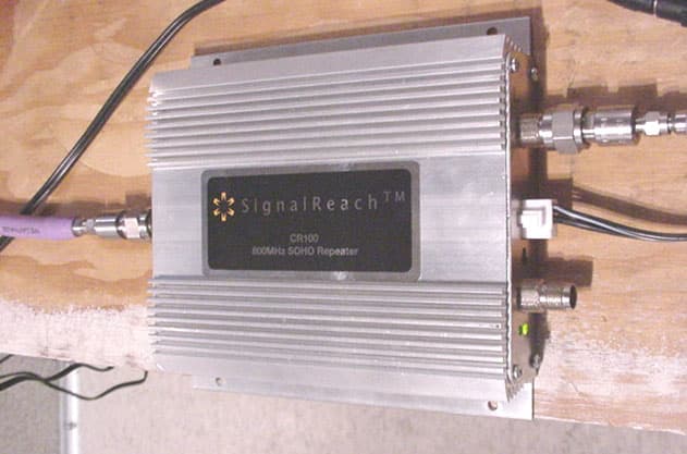
Click to zoom
Application Details
- Equipment Class
- TNB - Licensed Non-Broadcast Station Transmitter
- Date of Grant
- Mar 28, 2004
- Application Purpose
- Original Equipment
- Date of Application
- Jan 18, 2004
- Equipment Note
- Full Duplex Amplifier
- Frequency Range
- 869.00000000 - 894.00000000
- Company
- Arrista Technologies Inc.
- Country
- Canada
Documents & Files
Document Text
Text extracted from the exhibit documents filed with the FCC. Open a document above to read the original.
Users Manual
Installation & User Manual CR100 Bi-Directional Repeater Document Number: 102-2001-001 Product release: Document version:Prelim 2.02 Date:Jan 2004 Copyright1 Printing2Legal statements3 Trademarks 4 1Copyright 2000- 2004 SignalReach Inc., All Rights Reserved 2Printed in Canada 3Information is subject to change without notice. Arrista Technologies Inc. reserves the right to make changes in design or components as progress in engineering and manufacturing may warrant. 4 Trademarks are property of their respective owners Introduction In-building repeaters provide enhanced coverage of cellular telephone signals for areas that are confined or enclosed such as tunnels, underground parking garages, and within buildings. Many buildings are constructed of materials like metal, brick and concrete that attenuate cellular telephone signals. Symptoms such as dropped calls, broken audio and static indicate the need for an in-building repeater. The SignalReach TM CR100 Small Office Home Office (SOHO) Cellular Repeater extends cellular services into buildings, parking garages, tunnels and other poor coverage areas. The CR100 is designed for use with 800MHz cellular telephones and offers a cost-effective solution for small business and residential applications. The repeater is useful in areas where cellular service is available outside of the building but marginal indoors. The SignalReach TM CR100 is a stationary device that automatically reradiates signals from the base transmitters without channel translation, for the purpose of improving coverage of existing service by increasing the signal strength in dead spots. The repeater is a network-compatible device that amplifies cellular signals in both the uplink and downlink directions. The repeater is simple to install, and contains circuitry to ensure proper operating power levels, and as well, includes an automatic feedback and detection circuitry that detects, as a result of poor isolation between the subscriber and donor antennae. In this condition the repeater will adjust it’s gain to compensate for the abnormality, and warn the user through a visual indicator LED. The CR100 will enhance the cellular telephone user’s experience while complying with cellular network specifications. Linear operation is guaranteed under all conditions. The CR100 allows up to two indoor antennas to be used without the need of external components. Its auxiliary indoor antenna port allows a second indoor zone to be easily connected. The repeater can be powered by its AC adapter or through the in-building primary subscriber antenna port using an optional power inserter. Threshold of handset recei ver: -104dBm Base Station Signal strength outside buildi ng -90dBm Actual received power: as low as -130dBm (too low for handset) Building material attenuates signal by 10 to 40dB Threshold of handset recei ver: -104dBm Base Station Signal strength outside buildi ng -90dBm Actual received power: as low as -130dBm (too low for handset) Building material attenuates signal by 10 to 40dB This product is designed for installations where cellular coverage is available outside the building, and indoor coverage is inadequate. CR100 Features: • Easy Installation – No calibration required • Automatic feedback detection and warning circuitry • Auxiliary in-building antenna port provides enhanced coverage • Up to 20000sq.ft of free space coverage with only one interior antenna • Network-compatible operation • Auto levelling circuitry ensures linear operation • FCC approved • Optional power inserter available • External fault output signal Functional Description & Operation The repeater works on the principle of receiving the handset signal through a subscriber (indoor) antenna, amplifying or ‘boosting’ its signal level, and then passing it on to the donor antenna located outside the building. Signals from the cellular tower (downlink) are also amplified and passed to the subscriber antenna. Threshold of handset recei ver: -104dBm Base Station Signal strength outside buildi ng at antenna: -90dBm In-buildi ng repeater provides 40 dB gain Actual recei ved power (with losses inside building): -95dBm (10 dB ma rgin ) Threshold of handset recei ver: -104dBm Base Station Signal strength outside buildi ng at antenna: -90dBm In-buildi ng repeater provides 40 dB gain Actual recei ved power (with losses inside building): -95dBm (10 dB ma rgin ) Arrista’s CR-100 in-building repeater is a Class B Broadband device, it will process the entire cellular 800MHz spectrum. Input and output duplexers and band pass filters in the downlink and uplink path provide the repeater’s filtering and isolation. The maximum gain in each of the downlink and uplink path is 60dB. Both the downlink and uplink paths incorporate automatic gain/level control, to ensure that downlink and uplink power amplifiers are not overdriven and operate free of distortion. As well, the automatic gain/level control ensures that in normal operation the downlink and uplink gain mirror each other. The CR100 also has primary and secondary subscriber ports, allowing the repeater to double the in-building coverage area. Installation Procedure The repeater unit should be installed in a sheltered area, it’s operating temperature range is extensive, but is not sealed to prevent water (rain) ingress. The repeater unit should not be installed in an area where the ambient temperature is expected to exceed +60°C. The indoor and outdoor antenna locations must be chosen carefully to avoid re-generative feedback. Re-generative feedback occurs when the subscriber antenna picks up the donor antenna transmit signal. A general rule of thumb is to locate the antennae where the isolation is at least 10 dB greater than the operating repeater gain. The Arrista repeater has a maximum gain of 60dB in uplink path, as a result, the isolation required between the subscriber and the donor antenna is in a range of 70dB. The line of sight separation between the subscriber and do…
Text truncated - open the document above for the full version.
Users Manual
Installation & User Manual S i g n a l R e a c h T M CR100 Bi-Directional Repeater Document Title: Installation & User Manual Product release:CR100 Document version:CR100ManVer1.6wts.doc Date:March 04 Copyright1 Printing2Legal statements3 Trademarks 4 1Copyright 2000- 2004 SignalReach Inc., All Rights Reserved 2Printed in Canada 3Information is subject to change without notice. Arrista Technologies Inc. reserves the right to make changes in design or components as progress in engineering and manufacturing may warrant. 4 Trademarks are property of their respective owners Table of Contents Introduction_____________________________________________________________________________4 Functional Description & Operation__________________________________________________________4 Installation Procedure_____________________________________________________________________7 Product Maintenance______________________________________________________________________8 Operation________________________________________________________________________________8 Troubleshooting__________________________________________________________________________9 Specifications___________________________________________________________________________10 General Specifications____________________________________________________________________10 Introduction In-building repeaters provide enhanced coverage of cellular telephone signals for areas that are confined or enclosed such as tunnels, underground parking garages, and within buildings. Many buildings are constructed of materials like metal, brick and concrete that attenuate cellular telephone signals. Symptoms such as dropped calls, broken audio and static indicate the need for an in-building repeater. The SignalReach TM CR100 Small Office Home Office (SOHO) Cellular Repeater extends cellular services into buildings, parking garages, tunnels and other poor coverage areas. The CR100 is designed for use with 800MHz cellular telephones and offers a cost-effective solution for small business and residential applications. The repeater is useful in areas where cellular service is available outside of the building but marginal indoors. The SignalReach TM CR100 is a stationary device that automatically reradiates signals from cellular base stations without channel translation, for the purpose of improving coverage of existing service by increasing the signal strength in dead spots. The repeater is a network-compatible device that amplifies cellular signals in both the uplink and downlink directions. The repeater is simple to install, and contains circuitry to ensure proper operating power levels, and as well, includes an automatic feedback and detection circuitry that detects poor isolation between the subscriber and donor antennae. In this condition the repeater will adjust it’s gain to compensate for the abnormality, and warn the user through a visual indicator LED. The CR100 will enhance the cellular telephone user’s experience while complying with cellular network specifications. Linear operation is guaranteed under all conditions. The CR100 allows up to two indoor antennas to be used without the need of external components. Its auxiliary indoor antenna port allows a second indoor zone to be easily connected. The repeater can be powered by its AC adapter or through the in-building primary subscriber antenna port using an optional power inserter. This product is designed for installations where cellular coverage is available outside the building, and indoor coverage is inadequate. CR100 Features: • Easy Installation – No calibration required • Automatic feedback detection and warning circuitry • Auxiliary in-building antenna port provides enhanced coverage • Up to 20000 ft 2 of free space coverage with only one interior antenna • Network-compatible operation • Auto levelling circuitry ensures linear operation • FCC approved • Optional power inserter available • External fault output signal Functional Description & Operation The repeater works on the principle of receiving the handset signal through a subscriber (indoor) antenna, amplifying or ‘boosting’ its signal level, and then passing it on to the donor antenna located outside the building. Signals from the cellular tower (downlink) are also amplified and passed to the subscriber antenna. The SignalReach TM CR-100 in-building repeater is a Class B Broadband device, and processes the entire cellular 800MHz spectrum. Input and output duplexers and band pass filters in the downlink and uplink path provide the repeater’s filtering and isolation. The maximum gain in each of the downlink and uplink path is 60dB. Both the downlink and uplink paths incorporate automatic gain control, to ensure that downlink and uplink power amplifiers are not overdriven and operate free of distortion. The CR100 has primary and secondary subscriber ports, allowing the repeater to double the in-building coverage area. Installation Procedure Warning; Equipment Installation: Proper Grounding ¾ Follow the local building codes for installation of antennae on buildings. ¾ Ensure that the exterior mounted donor antenna is properly mounted and grounded for lightning protection. RF exposure Guidelines ¾ During transmitter operation, in order to meet RF Maximum Permissible Exposure Safety Guidelines, a minimum distance of 50 cm (20 in.) shall be maintained between the outdoor (uplink) antenna and personnel. ¾ During transmitter operation, in order to meet RF Maximum Permissible Exposure Safety Guidelines, a minimum distance of 20 cm shall be maintained between the indoor antenna and personnel. ¾ The maximum cellular outdoor (uplink) antenna gain authorized shall be limited to 18 dBi or less in order to meet RF exposure (MPE) limit as per FCC guidelines. ¾ The maximum cellular indoor (downlink) antenna gain authorized shall be limited to 9 dBi or less in order to meet RF exposure (MPE) limit as per FCC guidelines. When servicing or installing outdoor …
Text truncated - open the document above for the full version.
Cover Letter(s)
_______________________________________________________________ Document Type: Cover Letter Applicant: Arrista Technologies Incorporated 5-55 Henlow Bay Winnipeg, MB, Canada R3Y 1G4 Equipment Under Test (EUT): Bi-directional Cellular Amplifier Model: CR100 FCC ID: P35UTHNEXW9 Confidential Page 1 January 15, 2004 5-55 Henlow Bay, Winnipeg, Manitoba R3Y 1G4 Phone: 204-489-3200 Fax: 204-489-8300 _______________________________________________________________ Confidential Page 2 January 15, 2004 5-55 Henlow Bay, Winnipeg, Manitoba R3Y 1G4 Phone: 204-489-3200 Fax: 204-489-8300 Exhibit of Confidentiality To Whom It May Concern: Arrista Technologies would like the following submitted exhibits treated as confidential material: 1. Amplifier Schematic 2. Amplifier Block Diagram 3. Amplifier Parts Listing The amplifier design, specifically, the gain control circuitry is of novel design and a US patent has been filed on it. As there is no other amplifier design that incorporates the gain control function the way the CR100 does, we believe that we have a competitive advantage over competing designs out in the market place. Roman Wroczynski Director of Product Development Arrista Technologies Inc Tel: (204) 489-3200 Fax: (204) 489-8300 [email protected]
External Photos
_______________________________________________________________ Document Type: External Photos Applicant: Arrista Technologies Incorporated 5-55 Henlow Bay Winnipeg, MB, Canada R3Y 1G4 Equipment Under Test (EUT): Bi-Directional Cellular Amplifier Model: CR100 FCC ID: P35UTHNEXW9 IN ACCORDANCE WITH: FCC PART 2.1033 (c) Confidential Page 1 January 15, 2004 5-55 Henlow Bay, Winnipeg, Manitoba R3Y 1G4 Phone: 204-489-3200 Fax: 204-489-8300 _______________________________________________________________ Article 01- External Photo: Top View Article 02- External Photo: Bottom View Confidential Page 2 January 15, 2004 5-55 Henlow Bay, Winnipeg, Manitoba R3Y 1G4 Phone: 204-489-3200 Fax: 204-489-8300 _______________________________________________________________ Confidential Page 3 January 15, 2004 5-55 Henlow Bay, Winnipeg, Manitoba R3Y 1G4 Phone: 204-489-3200 Fax: 204-489-8300 Article 03- External Photo: Input Side View Article 04- External Photo: Signal Output Side View
ID Label/Location Info
_______________________________________________________________ Document Type: ID Label/Location Info Applicant: Arrista Technologies Incorporated 5-55 Henlow Bay Winnipeg, MB, Canada R3Y 1G4 Equipment Under Test (EUT): iDEN Cellular Amplifier Model: CR100 FCC ID: P35UTHNEXW9 IN ACCORDANCE WITH: FCC PART 2.925, 2.926, 2.1033(c) Confidential Page 1 January 15, 2004 5-55 Henlow Bay, Winnipeg, Manitoba R3Y 1G4 Phone: 204-489-3200 Fax: 204-489-8300 _______________________________________________________________ Confidential Page 2 January 15, 2004 5-55 Henlow Bay, Winnipeg, Manitoba R3Y 1G4 Phone: 204-489-3200 Fax: 204-489-8300 Article 01- Photo: FCC Identifier Location
Internal Photos
_______________________________________________________________ Document Type: Internal Photos Applicant: Arrista Technologies Incorporated 5-55 Henlow Bay Winnipeg, MB, Canada R3Y 1G4 Equipment Under Test (EUT): Bi-Directional Cellular Amplifier Model: CR100 FCC ID: P35UTHNEXW9 IN ACCORDANCE WITH: FCC PART 2.1033 (c) Confidential Page 1 January 15, 2004 5-55 Henlow Bay, Winnipeg, Manitoba R3Y 1G4 Phone: 204-489-3200 Fax: 204-489-8300 _______________________________________________________________ Confidential Page 2 January 15, 2004 5-55 Henlow Bay, Winnipeg, Manitoba R3Y 1G4 Phone: 204-489-3200 Fax: 204-489-8300 Article 01- Internal Photo: Top View Article 02- Internal Photo: Bottom View
Operational Description
Data Sheet CRV4.0 CR Series SOHO Cellular Repeater AMPS • •• • PCS • •• • TDMA • •• • GSM • •• • CDMA• •• • iDEN Description The SignalReach TM CR Series Small Office Home Office (SOHO) Cellular Repeaters extend cellular services into buildings and other poor coverage areas. The CR Series Repeaters are designed for use with cellular telephones (800 and 1900 MHz, and iDEN band) and offer a cost-effective solution for small business and residential applications. The repeaters are useful in areas where cellular service is available outside of the building and marginal indoors. The two-way radio functionality of cellular telephones is preserved. The repeaters are network-compatible devices that amplify cellular signals in both the uplink and downlink directions. The repeaters are simple to install, and contains circuitry to ensure proper operating power levels, and as well, include automatic low isolation and detection circuitry that detects low isolation between the indoor and outdoor antennas. In this condition, the repeaters will adjust their gain to compensate for the abnormality, and warn the user through an indicator LED. The CR Series Repeaters will enhance the cellular telephone user’s experience while complying with cellular network specifications. Linear operation is guaranteed under all conditions. The CR Series Repeaters allow up to two indoor antennas to be used without the need of external components. Their auxiliary indoor antenna port allows a second indoor zone to be easily connected. The repeaters can be powered by their AC adapter or through the in-building antenna port using an optional power inserter. Features • Easy Installation – no calibration required, • Up to 40,000 sq. ft. of free space coverage (with two interior antennas), • Automatic Low Isolation Detection and Indication Circuitry, • Feedback Overload Shutdown and Auto Start, • Auto levelling circuitry ensures linear operation, • Network-compatible operation, • Auxiliary in-building antenna port provides enhanced coverage, • FCC approved, • Optional power inserter available. CR Series Repeater Exterior Antenna Interior Antenna Optional 2nd Interior Antenna RF Specifications CR100 CR300 CR500 All Product Cellular iDEN PCS Frequency Range (MHz) 824-849 806-825 1850-1910 Low Isolation Detection Output Power (dBm) 1 +23 +23 +23 An amber LED indicator will indicate low isolation between indoor and outdoor antennas. Up-link Maximum Gain (dB) 60 60 60 Maximum Possible Exposure (MPE) At the interior antenna port, exposure to non-ionizing radiation meets or exceeds the permissible FCC mandated MPE specification. Frequency Range (MHz) 869-894 851-870 1930-1990 Group Delay < 200 nS Output Power (dBm) 1 +15 +15 +15 Down- link Maximum Gain (dB) 60 60 60 1 The RF output power specification is for a multi-carrier environment of up to three simultaneous TDMA carriers or one CDMA carrier. General Specifications Product All Power Requirements 120V AC adapter included Operating Temperature Range -40 to +60°C (-40 to 128°F); indoor use only Dimensions 135mm L x 152mm W x 33mm H (5.31” L x 5.98” W x 1.30” H) without RF connectors Net Weight 1.36 kg (3 lbs) RF Connectors TNC Female Recommended Indoor Antenna 3 dBi ceiling mount omni-directional Recommended Outdoor Antenna 2 dBi omni-directional Included Accessories 120V AC adapter Optional Accessories 2 Power inserter, indoor and outdoor omni-directional antennas, 5m (16.25’) low loss RF cable for the interior antenna interface 2 Recommended exterior antenna cable types are indicated in the product’s installation and user manual. An exterior directional antenna may be required in some cases where network coverage is weaker. For more Information Contact: [email protected] © 2002-2004 SignalReach TM . All rights reserved. All trademarks listed in this document are the property of their respective owners. Specifications are subject to change without notice. www.signalreach.com
Operational Description
Data Sheet CR Series SOHO Cellular Repeater AMPS • PCS • TDMA • GSM • CDMA• iDEN Description The SignalReach TM CR Series Small Office Home Office (SOHO) Cellular Repeaters extend cellular services into buildings and other poor coverage areas. The CR Series Repeaters are designed for use with cellular telephones (800 and 1900 MHz, and iDEN band) and offer a cost-effective solution for small business and residential applications. The repeaters are useful in areas where cellular service is available outside of the building and marginal indoors. The two-way radio functionality of cellular telephones is preserved. The repeaters are network-compatible devices that amplify cellular signals in both the uplink and downlink directions. The repeaters are simple to install, and contains circuitry to ensure proper operating power levels, and as well, include automatic low isolation and detection circuitry that detects low isolation between the indoor and outdoor antennas. In this condition, the repeaters will adjust their gain to compensate for the abnormality, and warn the user through an indicator LED. The CR Series Repeaters will enhance the cellular telephone user’s experience while complying with cellular network specifications. Linear operation is guaranteed under all conditions. The CR Series Repeaters allow up to two indoor antennas to be used without the need of external components. Their auxiliary indoor antenna port allows a second indoor zone to be easily connected. The repeaters can be powered by their AC adapter or through the in-building antenna port using an optional power inserter. Features • Easy Installation – No calibration required, • Up to 40,000 sq. ft. of free space coverage (with two interior antennas), • Automatic Low isolation detection and warning circuitry, • Feedback overload shutdown and auto start, • Auto levelling circuitry ensures linear operation, • Network-compatible operation, • Auxiliary in-building antenna port provides enhanced coverage, • FCC approved, • Optional power inserter available. CR Series Repeater Exterior Antenna Interior Antenna Optional 2nd Interior Antenna RF Specifications CR100 CR300 CR500 All Product Cellular iDEN PCS Frequency Range (MHz) 824-849 806-825 1850-1910 Low Isolation Detection Output Power (dBm) 1 +20 +20 +20 An LED indicator will indicate low isolation between indoor and outdoor antennas. Up-link Maximum Gain (dB) 60 60 60 Maximum Possible Exposure (MPE) Meets or exceeds the permissible FCC mandated MPE specification. Frequency Range (MHz) 869-894 851-870 1930-1990 Group Delay < 200 nS Output Power (dBm) 1 +15 +15 +15 Down- link Maximum Gain (dB) 60 60 60 1 The RF output power specification is for a multi-carrier environment of up to three simultaneous TDMA carriers or one CDMA carrier. General Specifications Product All Power Requirements 120V AC adapter included Operating Temperature Range -40 to +60°C (-40 to 128°F); indoor use only Dimensions 135mm L x 152mm W x 33mm H (5.31” L x 5.98” W x 1.30” H) without RF connectors Net Weight 1.36 kg (3 lbs) RF Connectors TNC Female Outdoor Antenna Not to exceed 18dBi Indoor Antenna Not to exceed 9 dBi Included Accessories 2 120V AC adapter For more Information Contact: [email protected] © 2002 SignalReach TM . All rights reserved. All trademarks listed in this document are the property of their respective owners. Specifications are subject to change without notice. www.signalreach.com CRV3.0
RF Exposure Info
FCC ID: P35UTHNEXW9 CELLULAR BAND REPEATERS REPORT NO.: ATEMC000043 FCC PART 22, SUBPART H Applicant: Arrista Technologies Inc. 1.9.5. RF EXPOSURE Test Type: Maximum Permissible Exposure FCC Para No.: 1.1310, 2.1093 Tested By: Paul Eberling Date: January 13, 2004 1.9.5.1. SPECIFICATION REQUIREMENT: As per FCC 47CFR§1.1301; FCC OET Bulletin 65, 97-01 “Evaluating Compliance with FCC Guidelines for Human Exposure to Radiofrequency Electromagnetic Fields” and FCC OET Bulletin 65, Supplement C, 01- 01, “Additional Information for Evaluating Compliance of Mobile and Portable Devices with FCC Limits for Human Exposure to Radiofrequency Emissions”, for transmitters operating in the 824-849 MHz range, paragraph 1.1310 Table 1 limits maximum permissible exposure (MPE) to f/1500 mW/cm 2 for uncontrolled environments and f/300 mW/cm 2 for controlled environments. The far field on-axis power flux density (W/m 2 ) is calculated using the following formula: S = G P T / 4πR 2 [6] Where: S = Power density (in appropriate units, e.g. mW/cm 2 ) G = Power gain of the antenna in the direction of interest relative to an isotropic radiator P T = Power input to the antenna (in appropriate units, e.g., mW) R = Distance to the center of radiation of the antenna (appropriate units, e.g., cm) It is important to note that the power gain factor, G, in Equation (1) is normally numeric gain. Therefore, when power gain is expressed in logarithmic terms, i.e., dB, a conversion is required using the relation: G=10^(dB/10) [7] For example, a logarithmic power gain of 14 dB is equal to a numeric gain of 25.12. 1.9.5.2. CR100 C ELLULAR SIGNAL AMPLIFIER PARTICULARS The following table shows the maximum downlink output power of the signal amplifier combined with an antenna with 9dBi gain. This is the maximum antenna gain permissible for the downlink signal as documented in the user/installation manual. The following table also shows the maximum uplink output power of the signal amplifier combined with an antenna with 18dBi gain. This is the maximum antenna gain permissible for the downlink signal as documented in the user/installation manual. The resulting radiated power density is compared to MPE limits for both uncontrolled and controlled environments. Equipment: CR100 Bi-Directional Cellular Signal Amplifier Copyright 2004 Arrista Technologies Inc. This document contains confidential information. Page 19 FCC ID: P35UTHNEXW9 CELLULAR BAND REPEATERS REPORT NO.: ATEMC000043 FCC PART 22, SUBPART H Applicant: Arrista Technologies Inc. 1.9.5.3. UP LINK (824-849MHZ) Uplink MPE Calculations Output power of the amplifier: 0.09 W maximum Antenna Gain: Maximum antenna gain allowed as described in user/installation manual. Isotropic Gain = 9 dBi Numerical Gain = 7.94 Operational Frequency: 824-849MHz Minimum distance (Controlled): From radiating source for personnel aware of radiofrequency equipment and who are able to limit their exposure time. (Installation Technicians) 20cm Antenna mounted in building interior Minimum distance (Uncontrolled): From radiating source for personnel unaware of radiofrequency equipment and who are not able to limit their exposure time. (General Public) 20cm Antenna mounted in building interior Calculated RF Power Density: 0.142 mW/cm 2 Maximum Permissible Exposure (MPE): Controlled 6 min avg exposure 2.75mW/cm 2 Uncontrolled 30 min avg exposure 0.55mW/ cm 2 1.9.5.4. TEST RESULTS: Complies 1.9.5.5. CALCULATIONS S = G P T / 4πR 2 [8] S = (7.94* .09*10³)/(4π*20 2 ) S = 714.6/(1600π) S = 0.142 mW/cm 2 Equipment: CR100 Bi-Directional Cellular Signal Amplifier Copyright 2004 Arrista Technologies Inc. This document contains confidential information. Page 20 FCC ID: P35UTHNEXW9 CELLULAR BAND REPEATERS REPORT NO.: ATEMC000043 FCC PART 22, SUBPART H Applicant: Arrista Technologies Inc. 1.9.5.6. DOWN LINK (869-894MHZ) Downlink MPE Calculations Output power of the amplifier: 0.032 W maximum Antenna Gain: Maximum antenna gain allowed as described in user/installation manual. Isotropic Gain = 18 dBi Numerical Gain = 63.1 Operational Frequency: 824-849MHz Minimum distance (Controlled): From radiating source for personnel aware of radiofrequency equipment and who are able to limit their exposure time. (Installation Technicians) 50cm Antenna mounted on building exterior Minimum distance (Uncontrolled): From radiating source for personnel unaware of radiofrequency equipment and who are not able to limit their exposure time. (General Public) 50cm Antenna mounted on building exterior Calculated RF Power Density: 0.064 mW/cm 2 Maximum Permissible Exposure (MPE): Controlled 6 min avg exposure 2.90mW/cm 2 Uncontrolled 30 min avg exposure 0.58mW/ cm 2 1.9.5.7. TEST RESULTS: Complies 1.9.5.8. CALCULATIONS S = G P T / 4πR 2 [9] S = (63.1* .032*10³)/(4π*50 2 ) S = 2019/(10000π) S = 0.064 mW/cm 2 Equipment: CR100 Bi-Directional Cellular Signal Amplifier Copyright 2004 Arrista Technologies Inc. This document contains confidential information. Page 21
RF Exposure Info
FCC ID: P35UTHNEXW9 CELLULAR BAND REPEATERS REPORT NO.: ATEMC000043 FCC PART 22, SUBPART H 1.1.1. RF EXPOSURE Test Type: Maximum Permissible Exposure FCC Para No.: 1.1310, 2.1093 Tested By: Paul Eberling Date: January 13, 2004 1.1.1.1. SPECIFICATION REQUIREMENT: As per FCC 47CFR§1.1301; FCC OET Bulletin 65, 97-01 “Evaluating Compliance with FCC Guidelines for Human Exposure to Radiofrequency Electromagnetic Fields” and FCC OET Bulletin 65, Supplement C, 01- 01, “Additional Information for Evaluating Compliance of Mobile and Portable Devices with FCC Limits for Human Exposure to Radiofrequency Emissions”, for transmitters operating in the 824-849 MHz range, paragraph 1.1310 Table 1 limits maximum permissible exposure (MPE) to f/1500 mW/cm 2 for uncontrolled environments and f/300 mW/cm 2 for controlled environments. The far field on-axis power flux density (W/m 2 ) is calculated using the following formula: S = G P T / 4πR 2 [6] Where: S = Power density (in appropriate units, e.g. mW/cm 2 ) G = Power gain of the antenna in the direction of interest relative to an isotropic radiator P T = Power input to the antenna (in appropriate units, e.g., mW) R = Distance to the center of radiation of the antenna (appropriate units, e.g., cm) It is important to note that the power gain factor, G, in Equation (1) is normally numeric gain. Therefore, when power gain is expressed in logarithmic terms, i.e., dB, a conversion is required using the relation: G=10^(dB/10) [7] For example, a logarithmic power gain of 14 dB is equal to a numeric gain of 25.12. 1.1.1.2. CR100 C ELLULAR SIGNAL AMPLIFIER PARTICULARS The following table shows the maximum downlink output power of the signal amplifier combined with an antenna with 9dBi gain. This is the maximum antenna gain permissible for the downlink signal as documented in the user/installation manual. The following table also shows the maximum uplink output power of the signal amplifier combined with an antenn…
Text truncated - open the document above for the full version.
Contact Information
Applicant
Roman Wroczynski(Manager, Product Development)
Technical Contact
Arrista Technologies Inc.Paul Eberling
[email protected]204-489-3200
5-55 Henlow Bay · Winnipeg · Canada
Test Firm
Arrista TechnologiesElwood Friesen
Technical Specifications
| # | Rule Parts | Frequency Range | Power Output | Emission | Tolerance |
|---|---|---|---|---|---|
| 4 | 22H | 869 MHz - 894 MHz | 30.00 mW | DXW | Amp |
Other Applications from Arrista Technologies Inc.
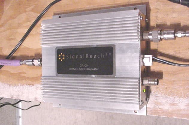
P35WYPCJTE6
Feb 03, 2005Full Duplex Amplifier
Equipment Class
PCB - PCS Licensed Transmitter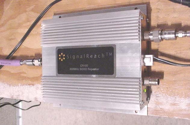
P35SH2U64GG
Aug 04, 2004Full Duplex Amplifier
Equipment Class
AMP - Amplifier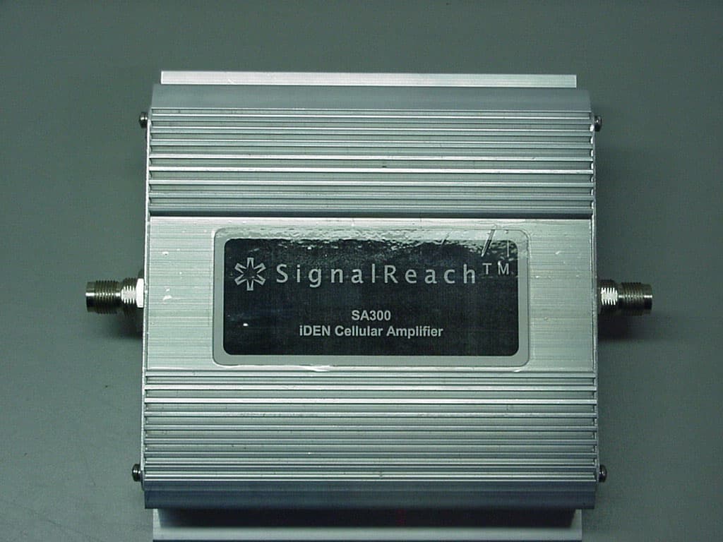
P35K7P9YE8S
Jun 10, 2003Full Duplex Amplifier
Equipment Class
AMP - Amplifier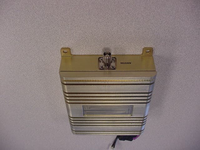
P35SSG-819-1W2W
Jan 06, 2003Cellular and PCS Band Full Duplex Amplifier
Equipment Class
AMP - Amplifier
P35ARR-800-P207
Feb 26, 2002Cellular Band Bi-Directional Power Amplifier
Equipment Class
AMP - Amplifier