P3YSPOTCELL0008Spotcell 100 Release 2.3
Spotwave Wireless Ltd.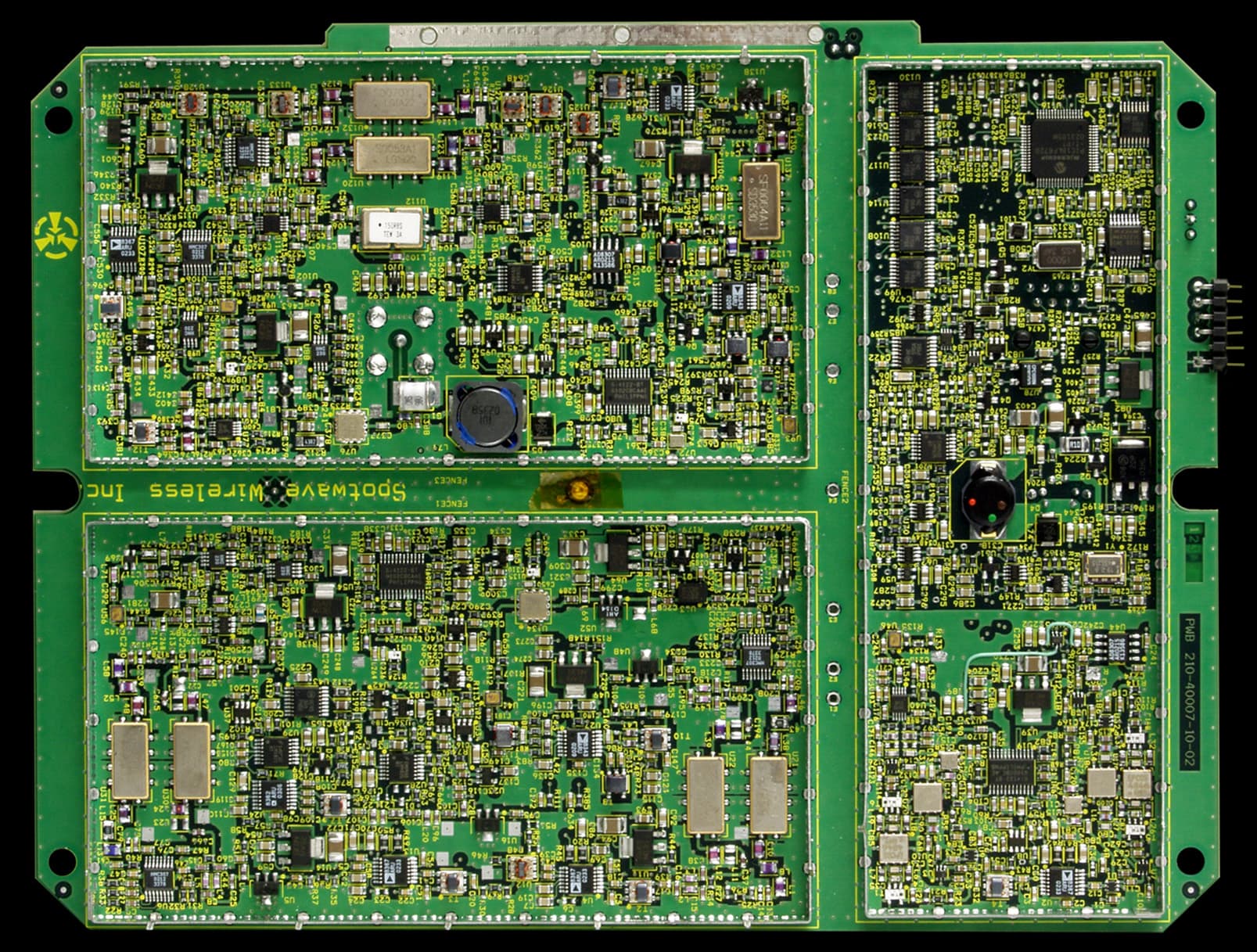
Click to zoom
Application Details
- Equipment Class
- AMP - Amplifier
- Date of Grant
- Jul 23, 2003
- Application Purpose
- Original Equipment
- Date of Application
- Jul 23, 2003
- Equipment Note
- Spotcell 100 Release 2.3
- Frequency Range
- 869.04000000 - 893.97000000
- Company
- Spotwave Wireless Ltd.
- Country
- Canada
Documents & Files
Document Text
Text extracted from the exhibit documents filed with the FCC. Open a document above to read the original.
Users Manual
Spotwave Wireless Inc.1 Hines Road, Ottawa ON K2K 3C7 Canada 780-00009-01-01 © 2003 Spotwave Wireless Inc. All rights reserved. Printed in Canada Spotwave and SpotCell are trademarks of Spotwave Wireless Inc. Patents pending. SpotCell Coverage Extension Kit Installation Guide SpotCell Coverage Extension Kit Installation Guide ™ www.spotwave.com 2. Coverage Extension antenna location WARNING: The extended coverage antenna should be mounted in locations where people will not approach within 20 cm in front of the antenna. The main CU and the auxillary antennas should never be co-located side by side and facing in the same direction. The two antennas must have a minimum of 10cm of separation when facing in opposite direction. The SpotCell Coverage Extension should be connected to the Coverage Unit (CU) only after the SpotCell 100 or SpotCell 200 system has been properly installed. The SpotCell Coverage Extension kit extends SpotCell system coverage into hard to reach places that are blocked by obstructions such as dense walls or shadowed by elevator shafts or duct work. 1. Parts List ! ! ! ! Coverage Extension antenna Adapter cable coax connector 25m RG6 cable 3. CU connection Connect the Adapter cable to the Coverage Extension antenna (MCX) connector on the back of the CU. The CU can be powered and operational while connecting the Coverage Extension antenna. 4. Adapter cable to RG6 Join the other end of the adapter cable to one end of the provided RG6 cable with the supplied connector. 5. Connect RG6 to Coverage Extension Antenna Connect the other end of the RG6 cable to the F-connector on the Coverage Extension antenna. Finally, mount the Coverage Extension antenna in a suitable location on the wall or ceiling. Coverage Extension antenna RG6 cable Adapter cable Coverage Extension antenna connector LIMITED WARRANTY Spotwave Wireless Inc. warrants to the original Purchaser that the Spotwave SpotCell Coverage Extension is free from defects in material and workmanship undernormal use andservice foraperiodof12months fromthe dateofshipment fromSpotwave(the "Limited WarrantyPeriod"). Adapter cable Connector RG6 cable Adapter cable DU CU Auxiliary Antenna > 20 cm > 10 cm CU Antenna · · · · · Gain +3 dBi Elevation Beamwidth 180° Azimuth Beamwidth 175° Front-to-Back 12 dB Horizontally Polarized Extension Antenna Characteristics
Users Manual
SpotCell™ 100 SERIES USER MANUAL Affordable, reliable In-building wireless coverage solutions. Technical Support The SpotCell TM serial number must be available to authorize technical support and/or to establish a return authorization for defective units. The serial number is located on the back of the Coverage Unit (CU) and Donor Unit (DU) as well as the box in which they were delivered. Additional support information may be obtained by accessing the SpotwaveWireless Inc. website at www.spotwave.com. To contact support by telephone, call your local Spotwave vendor, or if you are unable to reach your vendor, contact Spotwave Wireless at 1-877-610- 9586. Important Safety Information Wa r n i n g ! For your safety, beware of power lines and ensure appropriate safety measures are maintained at all times during the installation of the SpotCell equipment. If equipment not shipped with the SpotCell system is to be used during installation or mounting, follow all equipment manufacturer’s instructions in proper use to ensure injury is avoided. The DU and CU of the SpotCell are low power transmitters. As with a cell phone antenna, avoid unneccessary contact with the front of the units after installed. Mount the units in a location where people will not approach within 1 meter of the front of the DU and 20 centimeters in front of the CU. When deploying the extended coverage antenna, there must be a minimum separation of 10 cm between the main CU and the extended coverage antenna with the antennas facing in opposite directions. The extended coverage antenna should be mounted in locations where people will not approach within 20 cm in front of the antenna. This manual outlines installation instructions and the appendix offers practical safety tips (see page 43 entitled ‘Safety Hints’). If you are not sure about a safe installation, do not attempt to install it yourself. Call a professional installer for help. iiSpotCell LIMITED WARRANTY AND LIMITATION OF LIABILITY: 1. What is Covered and for How Long? Spotwave Wireless Inc. ("Spotwave") warrants to the original Purchaser that the Spotwave SpotCell System (the "System") is free from defects in material and workmanship under normal use and service for a period of 12 months from the date of shipment from Spotwave (the "Limited Warranty Period"). 2. What is not covered? This Limited Warranty is conditioned upon proper use of the System by the Purchaser. This Limited Warranty does not cover (and will become null and void in the event of ): (a) defects or damage resulting from accident, misuse, abuse, neglect, unusual physical, electrical or electromechanical stress, modification of the System or any part thereof, or cosmetic damage; (b) removal, alteration or defacing of the serial number or other identifying marks on the System; (c) all plastic surfaces and other externally exposed components that are scratched or damaged due to normal use; (d) malfunctions resulting from the use of the System in conjunction with accessories, products or (ancillary) or peripheral equipment not provided by Spotwave; or (e) defects or damage from unauthorized or improper testing, operation, maintenance, installation, servicing or adjustment of the System. Any repairs or replacements provided by Spotwave outside of the Limited Warranty Period (including repairs to or replacement after the end of the Warranty Period), or in excess of the services provided during the Limited Warranty Period, will subject to Spotwave's then prevailing rates. 3. What are Spotwave's Obligations and how do you make a claim? During the Limited Warranty Period, Spotwave will repair or replace, at Spotwave's sole option, without charge to Purchaser, any defective component of the System, provided that the System is returned promptly upon discovery of the defect and during the Limited Warranty Period. To obtain service, Systems must be returned to an authorized service facility in the original packaging or packaging adequate for shipping, accompanied by Purchaser's sales receipt or comparable substitute proof of sale showing the date of purchase and the serial number of the System. A valid RMA is required prior to any return. To locate your nearest authorized service facility, call Spotwave Customer Service at 1-877-610-9586. Spotwave may, at Spotwave's sole option, use rebuilt, reconditioned, or new parts or components when repairing any System or replace a System with a rebuilt, reconditioned or new System. Repaired Systems will be warranted for a period equal to the remainder of the original Limited Warranty Period for the original System or for 90 days, whichever is longer. All replaced parts, components, boards or equipment shall become the property of Spotwave. If Spotwave determines that any System is not covered by this Limited Warranty, Purchaser must pay the costs for all parts, shipping, and labor charges for the repair or return of such System. 4. What are the Limits on Spotwave's Liability? EXCEPT FOR THE WARRANTY IN PARAGRAPH 1, THE SYSTEMS AND ANY ASSOCIATED SERVICES ARE PROVIDED BY SPOTWAVE ON AS 'AS IS' BASIS AND THERE ARE NO OTHER REPRESENTATIONS, WARRANTIES OR CONDITIONS, ,EXPRESS OR IMPLIED, WRITTEN OR ORAL, ARISING BY STATUTE, OPERATION OF LAW, COURSE OF DEALING, USAGE OF TRADE OR OTHERWISE, REGARDING THEM OR ANY OTHER PRODUCT OR SERVICE PROVIDED HEREUNDER OR IN CONNECTION HEREWITH BY SPOTWAVE. SPOTWAVE DISCLAIMS ANY IMPLIED WARRANTIES OR CONDITIONS OF DURABILITY, MERCHANT ABILITY, MERCHANTABLE QUALITY, SATISFACTORY QUALITY, NON- INFRINGEMENT OR FITNESS FOR A PARTICULAR PURPOSE. SPOTWAVE DOES NOT REPRESENT OR WARRANT THAT THE SYSTEMS WILL MEET ANY OR ALL OF PURCHASERS' PARTICULAR REQUIREMENTS, THAT THE SYSTEMS WILL OPERATE ERROR-FREE OR UNINTERRUPTED OR THAT ALL ERRORS OR DEFECTS IN THE SYSTEMS CAN BE FOUND TO BE CORRECTED. System performance is dependant upon the performance and availability of services or technology provided by third parties and Spotwave is not responsible for…
Text truncated - open the document above for the full version.
ID Label/Location Info
PRODUCT INDUSTRY CANADA ID. FCC ID CU 800MHz 4189A - 00000002 P3YSPOTCELL0008 CU 800(CN) NOT USED (BLANK) NOT USED (BLANK)
ID Label/Location Info
UNIT LABEL LOCATION
Operational Description
Spotwave Wireless Inc. 1 Hines Road Ottawa ON K2K 3C7 Canada Tel: (613) 591-1662 Fax: (613) 591-8107 www.spotwave.com Subject: Operational Description of Spotcell 100, Release 2.3 The SpotCell 100 uses an IF frequency to perform gain control and filtering functions in both the downlink and uplink directions. The same LO signal is used to provide both down-conversion and up-conversion of the RF signal. In this configuration the output RF frequency is independent of the actual LO frequency, or any LO frequency error. The LO signal is generated by a frequency sythesizer that phase locked to a TCXO reference source, which has a maximum frequency error of +/- 2.5 ppm (see attached vt204 data sheet). However as noted above, because the same LO is used to convert to and from the IF frequency, this error is not transferred to the output frequency. The only sources of spurious radiation within the SpotCell are the Local Oscialltors used in the uplink and downlink, and the clock frequency used by the on-board micro-controller. The LO frequencies have been selected to prevent in-band spurious signals from being generated. Out of band spurious signals are filtered by SAW RF filters which are located between the uplink and downlink gain stages. The uplink and downlink oscillators and associated components are located in separate shielded compartments to control stray radiation. The microprocessor and associated digital circuits that use the 15MHz clock are housed in their own, separate shielded compartment to ensure that the clock and harmonics do not create spurious signals at the antennas. In addition, each RF stage in the uplink and downlink chain has its own decoupling components to prevent clock and LO signals from entering the signal path through the power supply. The PCB uses 3 separate ground planes to provide shielding and provide a low impedance ground for the RF stages and decoupling components. SpotCell 100 uses an AGC circuit in both the uplink and downlink to control the RF power fed to the output stages. These stages are calibrated during manufacture to ensure that output amplifiers are limited to operating at 10dB or more below the maximum output power of the device. This ensures linear operation, and prevents any distortion of the signal that may affect the occupied bandwidth of the signal (modulation). The AGC circuit use logarithmic detectors to measure the AGC output power, together with an integrator and linear voltage controlled amplifier. This AGC configuration allows the system to operate linearly over a wide dynamic range. In addition, a supervisory system is used to monitor the input power level and to shut down the downlink or uplink if the input power exceeds the maximum specified. The final amplifier stage in the downlink is a linear RF amplifier part number Ah1(see attached PDF data sheet). This device is operated at a supply voltage of 5V, and current of 150 - 180mA.
Operational Description
WJ Communications, Inc.• Phone: 1-800-WJ1-4401 • FAX: 408-433-5649 • e-mail: [email protected] • Web site: www.wj.com September 2000 AH1 Product Description The AH1 is a high dynamic range amplifier packaged in a low cost surface mount package. The combination of low noise figure and high output IP3 at the same bias point makes it ideal for receiver and transmitter applications. The AH1 achieves +41 dBm IP3 at a mounting temperature of 85 ̊C with an associated MTTF of >100 years. The package is a SOT-89. All devices are 100% RF & dc tested. The product is targeted for applications where high linearity is required. Product Features • 250-3000 MHz Bandwidth • 41 dBm Output IP3 • 2.7 dB Noise Figure • 13.5 dB Gain • 21 dBm P1dB • High Reliability • SOT-89 Surface Mount Package • Single +5 V Supply Functional Diagram 4 123 Function Pin No. Input1 Ground2 Output Bias3 Ground4 High Dynamic Range Amplifier Specifications ParameterUnitsMinimumTypicalMaximumCondition Frequency RangeMHz250-3000 S21-Gain dB12.413.5 S11-Input Return LossdB-8 S22-Output Return LossdB-15 Output IP3dBm3741 Noise FiguredB2.7 Output P1dBdBm21 Operating Current RangemA120 150180Vdd = 5.0 V Supply Voltage V5 Test conditions unless otherwise noted. 1. T = 25°C, Vdd = 5.0, Freq = 800 MHz, 50 ohm system. 2. 3OIP Measured with two tones at an output power of 5 dBm/tone separated by 10 MHz. The suppression on the largest IM3 product is used to calculate the 3OIP using a 2:1 slope rule. 3. S21 and S11 can be improved in the band of interest using a single input shunt microstrip to ground. 4. Degradation of 3OIP occurs at low temperatures. Minimum typical 3OIP at -40 ̊C is 35dBm. 5. MTTF calculated with channel temperature at 155 ̊C and ground lead temperature at 85 ̊C. Absolute Maximum Ratings ParameterRating Operating Case Temperature-40 to +85°C Storage Temperature -40 to +125 °C Junction Temperature+155°C Thermal Resistance (θ JC )85°C/W Supply Voltage+6.0 V Input RF Power (continuous) +10 dBm Operation of this device above any of these parameters may cause permanent damage. Ordering Information Part No.Description AH1High Dynamic Range Amplifier (Available in tape and reel) AH1-PCBFully Assembled Application Circuit The Communications Edge ™ AH1 Advanced Product Information WJ Communications, Inc.• Phone: 1-800-WJ1-4401 • FAX: 408-433-5649 • e-mail: [email protected] • Web site: www.wj.comSeptember 2000 Application Circuit: 250-650 MHz Application Circuit: 0.9-2.5 GHz Frequency (MHz) 0100 200 300 400 500700 8006001000900 S-Parameters 20 10 0 -10 -20 -30 Typical Specifications Frequency250 MHz650 MHZ Magnitude S2115.4 dB14.2 dB Magnitude S11-11.0 dB-11.5 dB Magnitude S22-19.9 dB-14.0 dB IP340.0 dBm40.0 dBm Noise Figure2.8 dB2.8 dB Bias Vd = 5 V, Id = 160 mA FR4 Board Layout (T = 14 Mil) Schematic S21 S11 100 mil200 mil SOURCE 0603 Package C = 56 pF 0603 Package C = 56 pF 0603 Package L = 82 nH L = 15 nH 0603 Package +5 V GATEDRAIN S22 Z = 50 ohm 100 mil 200 mil AH1 C = 56 pF L = 15 nH RF OUT RF IN DC 5 V C = 56 pF L = 82 nH Z = 50 ohm Magnitude (dB) Frequency (GHz) 00.511.5232.5 S-Parameters 20 10 0 -10 -20 -30 Typical Performance Frequency0.9 GHz1.9 GHZ2.4 GHZ Magnitude S2114.2 dB12.4 dB11.7 dB Magnitude S11-18.5 dB-12.9 dB-13.6 dB Magnitude S22-14.7 dB-12.6 dB-11.0 dB IP339.0 dBm41.0 dBm40 dBm Noise Figure2.7 dB3.4 dB3.7 dB Bias Vd = 5 V, Id = 170 mA FR4 Board Layout (T = 14 Mil) Schematic S21 S11 300 mil GND GND 0603 Package C = 56 pF 0603 Package C = 56 pF 0603 Package L = 12 nH 0603 Package L = 100 nH 0603 Package C = 56 pF 0603 Package L = 5.6 nH +5 V INPUTOUTPUT S22 Z = 22 ohm 300 mil AH1 C = 56 pF C = 56 pF RF OUT RF IN DC 5 V C = 56 pF L = 12 nH L = 100 nH L = 5.6 nH 3 or more Via Grounds req. WJ Communications, Inc.• Phone: 1-800-WJ1-4401 • FAX: 408-433-5649 • e-mail: [email protected] • Web site: www.wj.comSeptember 2000 Application Circuit: 1900 MHz Frequency (GHz) 00.51.01.52.03.02.5 S-Parameters 20 10 0 -10 -20 -30 Typical Specifications Frequency1900 MHz Magnitude S2112.6 dB Magnitude S11-14.5 dB Magnitude S22-11.7 dB IP341.0 dBm Noise Figure2.5 dB Bias Vds = 5 V, Id = 170 mA FR4 Board Layout (T = 14 Mil) Schematic S21 S11 100 mil200 mil SOURCE 0603 Package C = 56 pF 0603 Package C = 2.2 pF 0603 Package C = 56 pF 0603 Package L = 47 nH 0603 Package L = 2.7 nH 0603 Package L = 2.7 nH +5 V GATEDRAIN S22 Magnitude (dB) Z = 38 ohm 100 mil 200 mil AH1 C = 56 pF L = 2.7 nH C = 2.2 pF L = 6.8 nH RF OUT RF IN DC 5 V C = 56 pF L = 47 nH Z = 38 ohm Application Circuit: 900 MHz Frequency (GHz) 00.51.01.52.03.02.5 S-Parameters 20 10 0 -10 -20 -30 Typical Specifications Frequency900 MHz Magnitude S2114.3 dB Magnitude S11-16.5 dB Magnitude S22-13.9 dB IP341.0 dBm Noise Figure2.5 dB Bias Vd = 5 V, Id = 170 mA FR4 Board Layout (T = 14 Mil) Schematic S21 S11 100 mil200 mil SOURCE 0603 Package C = 56 pF 0603 Package C = 56 pF 0603 Package L = 47 nH 0603 Package L = 12 nH +5 V GATEDRAIN S22 Z = 38 ohm 100 mil 200 mil AH1 C = 56 pF L = 12 nH RF OUT RF IN DC 5 V C = 56 pF L = 47 nH Z = 38 ohm Magnitude (dB) AH1 Advanced Product Information WJ Communications, Inc.• Phone: 1-800-WJ1-4401 • FAX: 408-433-5649 • e-mail: [email protected] • Web site: www.wj.comSeptember 2000 Performance Charts(V DS = 5.0 V, I DS = 150 mA, T = 22°C, unmatched device in a 50 ohm system) IP3 (dBm) Frequency (MHz) 500100015002000250035003000 IP3 vs. Frequency Gain vs. Power Out Output Power (dBm)Output Power (dBm) 2.54.56.58.512.510.514.516.5 45 40 35 30 25 20 Gain (dB) 14.5 14.0 13.5 13.0 12.5 12.0 Output IP3 vs. Power Out 2.54.56.58.512.510.514.516.5 Output IP3 (dBm) 45 40 35 30 25 20 IP3 Pull Circles Temperature (C) Gain vs. Temperature Gain (dB) -40-20020406080 15.0 12.0 12.5 13.0 13.5 14.0 14.5 IP3 (dBm) Temperature (C) -50-250255010075 IP3 vs. Temperature 43 37 38 39 40 41 42 Frequency = 900 MHzFrequency = 900 MHz Frequency = 900 MHz Vds = 5.0 V, 100% Idss, T = 22∞C 36 37 39 41 4.0 3.0 2.0 1.5 IP3 = 35 VSWR = 5.0 38 50% Idss 75% Idss 100% Idss MTTF vs. Temperature Ground …
Text truncated - open the document above for the full version.
RF Exposure Info
Spotwave Wireless Inc. 1 Hines Road Ottawa ON K2K 3C7 Canada Tel: (613) 591-1662 Fax: (613) 591-8107 www.spotwave.com Maximum Permissible Exposure (MPE) Compliance Statement for the SpotCell 100 (800MHz Cellular) Adaptive Repeater for Uncontrolled Exposure (general population) and Occupational Workers (controlled exposure). The SpotCell 100 (800MHz) equipment has been tested and the performance characterized in accordance with the MPE requirement of CFR 47, Part 1.1310. The system is a low power adaptive repeater, having integral antennas built into the CU and DU modules. For the highest frequency of the Cellular Services, 894MHz, the MPE limit for the General Population is 0.6mW/cm 2 (894/1500 = 0.596≈0.6mW/cm 2 ). For Occupational Workers (controlled exposure), the MPE limit is 3.0mW/cm 2 (894MHz/300 = 2.98mW/cm 2 ≈ 3.0mW/cm 2 ). For the DU, with a rated output power of +20dBm and antenna gain of 10dBi, the power density is 0.6mW/cm 2 at a distance of 11.5cm from the antenna. The analysis used is: S = Power Density = EIRP/(4πR 2 ) S= 0.6mW/cm 2 = 1000mW/(4πR 2 ) Solving for R, this gives a value of 11.5cm. For occupational workers, the Maximum Permissible Exposure (MPE) limit is given by 3mW/cm 2 , by CFR 47, Part 1.1310. (f/300 mW/cm 2 ). The prediction methods provided are based on worst-case far-field calculations: S = EIRP/(4πR 2 ), Where S is power density at a distance R from the radiating element, in mW/cm 2 . EIRP is the radiated power in mW(milliWatts). R is the distance in cm. Using this calculation, for the DU of EIRP = 1000mW (30dBm) S = 3mW/cm 2 . EIRP = 1000mW. R = 5.2cm For the CU, a similar analysis is used for a rated output power of +7dBm per RF port and antenna gain of 3dBi. For this release, Spotcell 100 Rel 2.3, the CU has two downlink output RF ports. The main RF port feeds the integral antenna. The second RF port, with MCX connector, shall be used for extended coverage by customers who wish to do so. The RF output from the second port will be conducted via a coax cable to an external antenna with a maximum gain of +3dBi. Spotwave Wireless shall provide the external antenna in a similar housing as the main CU. There will be a maximum of 6dB cable loss and minimum of 1dB cable loss. As a result, the radiated out put power from the external antenna shall always be less than the main antenna. MPE Analysis: The distance from the main CU antenna at which the power density is 0.6mW/cm 2 is 1.15cm for the general public and the distance at which the power density is 3mW/cm 2 is 0.50cm for occupational persons. For the main CU: S = 0.6mW/cm 2 for the general population and 3mW/cm 2 for occupational persons. EIRP = 10mW (10dBm) Using the prediction method, S = EIRP/(4πR 2 ): R = 1.15cm for the general population and R = 0.50cm for occupational workers. The integral radome on CU provides > 1.5cm physical separation from the antenna so that no warning statement is required for this module. For the external antenna for extended coverage, there will be at least 1dB of cable loss. The external antenna shall have a maximum of +3dBi gain. The maximum EIRP from the external antenna shall be = 8mW (9dBm). Using the prediction method, S = EIRP/(4πR 2 ): R= 1.03cm for the general public and R = 0.50cm for occupational workers. The housing on the main CU and the external antenna provides a separation >1.5cm between the radiating element and the radome and so no warning statement shall be required for both the main CU and the external antenna. The two antennas are never going to be co-located. Spotwave Wireless Inc will make a recommendation, in the customer manual for the extended coverage KIT, that a minimum of 10meters of separation be applied when the antennas are deployed facing in opposite directions. When the main CU and the extended coverage antenna are deployed 10cm apart and facing in opposite directions, the back lobe of the radiation from one antenna will be super-imposed on top of the main radiated signal. The main CU antenna and the extended coverage antenna have a Front-to-back (F/B) ratio of 12dB. The additional radiation from the second antenna shall be –3dBm (9dBm –12dB) or –0.5mW. The free space loss for a separation of 10cm and at Maximum frequency of 894MHz is 11dB (calculated below). For this deployment scenario, the MPE calculation shall be: Free Loss = 32.44+20log( f )+20log (d), f in MHz and d is in Km. = 32.44+20log(894)+20log 10 -4 = 11.0dB. EIRP in front of main antenna due to external antenna = 9dBm – 12dB – 11dB = - 14dBm = 0.04mW Total EIRP = 10.04mW 0.6mW/cm 2 = (Total EIRP)/ (4πR 2 ) = 10.04mW/(4πR 2 ), for the general public and 3mW/cm 2 = (Total EIRP)/ (4πR 2 ) = 10.04mW/(4πR 2 ), for occupational persons. Solving for R gives a distance of 1.15cm for the general public and a distance of 0.52cm for occupational persons. This is still below the 20cm safety margin required. Worst Case scenario : In an unlikely scenario, if the two antenna are separated by 10cm and facing in the same direction, the total EIRP in front of the main CU due to the external antenna shall be: 10mW (from the main CU) + 0.6mW (from external antenna). The EIRP from the external antenna in front of the main CU is calculated as follows: 9dBm – 11dB (due to free space of 10cm) = -2dBm = 0.6mW. MPE distance for this scenario is: 0.6mW/cm 2 = (Total EIRP)/ (4πR 2 ) = 10.6mW/(4πR 2 ), for general public. 3mW/cm 2 = (Total EIRP)/ (4πR 2 ) = 10.6mW/(4πR 2 ), for occupational persons. Solving for R gives a distance of 1.18cm for the general public and 0.53cm for occupational persons. Not that this type of deployment is not recommended by Spotwave Wireless Inc. This calculation is included to show that even in the worst case type of deployment the safety requirement within the 20cm distance is met. MPE Limits Summary: DU: 11.50cm for the general public and at 5.20cm for occupational workers. CU: 1.15cm for the general public and at 0.50cm for occupational workers. External antenna: 1.03cm f…
Text truncated - open the document above for the full version.
RF Exposure Info
Prediction of MPE limit at a given distance Spotwave Wireless P3YSPOTCELL0008 Equation from page 18 of OET Bulletin 65, Edition 97-01where: S = power density P = power input to the antennaG = power gain of the antenna in the direction of interest relative to an isotropic radiatorR = distance to the center of radiation of the antenna Maximum peak output power at antenna input terminal: 10.00 (dBm) Maximum peak output power at antenna input terminal: 10 (mW) Antenna gain(typical): 3 (dBi) Maximum antenna gain: 1.995262315 (numeric) Prediction distance: 20 (cm) Prediction frequency: 869-894 (MHz) MPE limit for uncontrolled exposure at prediction frequency: 0.6 (mW/cm^2) Power density at prediction frequency: 0.003969 (mW/cm^2) Maximum allowable antenna gain: 24.79421106 (dBi) Margin of Compliance at 20cm = 21.8dB 2 4 R PG S π =
Test Report
Master: Generic FCC Date: October 16, 2001 Test Report: 3W07299 Applicant: Spotwave Wireless Inc. 1 Hines Rd. Ottawa, Ontario K2K 3C7 Equipment Under Test: SpotCell 100 CU (EUT) Low Power Cellular Band Repeater In Accordance With: FCC Part 22, Subpart H FCC ID. : P3YSPOTCELL0008 Tested By: Nemko Canada Inc. 303 River Road, R.R. 5 Ottawa, Ontario K1V 1H2 Authorized By: Russell Grant, Senior Technical Assessor. Date: 14 July 2003 Total Number of Pages: 34 Nemko Canada Inc. FCC PART 22, SUBPART H PROJECT NO.: 3W07299 EQUIPMENT: SpotCell 100, Low Power Cellular Band Repeater Page 2 of 34 Table of Contents Section 1. Summary of Test Results ...................................................................................3 Section 2. General Equipment Specification......................................................................5 Section 3. RF Power Output ................................................................................................7 Section 4. Occupied Bandwidth ........................................................................................10 Section 5. Spurious Emissions at Antenna Terminals ....................................................19 Section 6. Field Strength of Spurious Emissions .............................................................29 Section 7. Frequency Stability...........................................................................................31 Section 8. Block Diagrams .................................................................................................32 Section 9. Test Equipment List .........................................................................................34 Nemko Canada Inc. FCC PART 22, SUBPART H PROJECT NO.: 3W07299 EQUIPMENT: SpotCell 100, Low Power Cellular Band Repeater Page 3 of 34 Section 1. Summary of Test Results General All measurements are traceable to national standards. These tests were conducted on a sample of the equipment for the purpose of demonstrating compliance with FCC Part 22, Subpart H. New Submission Production Unit Class II Permissive Change Pre-Production Unit A M P Equipment Code THIS TEST REPORT RELATES ONLY TO THE ITEM(S) TESTED. THE FOLLOWING DEVIATIONS FROM, ADDITIONS TO, OR EXCLUSIONS FROM THE TEST SPECIFICATIONS HAVE BEEN MADE. See “ Summary of Test Data”. TESTED BY: ______________________________ DATE: 14 July 2003 Glen Westwell, Wireless Technologist Nemko Canada Inc. authorizes the above named company to reproduce this report provided it is reproduced in its entirety and for use by the company’s employees only. Any use which a third party makes of this report, or any reliance on or decisions to be made based on it, are the responsibility of such third parties. Nemko Canada Inc. accepts no responsibility for damages, if any, suffered by any third party as a result of decisions made or actions based on this report. This report applies only to the items tested. Nemko Canada Inc. FCC PART 22, SUBPART H PROJECT NO.: 3W07299 EQUIPMENT: SpotCell 100, Low Power Cellular Band Repeater Page 4 of 34 Summary Of Test Data Name Of Test Para. No. Result RF Power Output 2.1046 Complies Occupied Bandwidth 2.1049 Complies Spurious Emissions at Antenna Terminals 2.1051 Complies Field Strength of Spurious Emissions 2.1053 Complies Frequency Stability 2.1055 N/A Notes: This RF device, the Spotcell 100 CU is part of a Cellular Band amplifier. It is used to enhance signals in the Downlink direction. The EUT is an f1-f1 amplifier, as such frequency stability was not performed. Indoor Temperature: 22 °C Humidity: 45 % Outdoor Temperature: 28 °C Humidity: 40 % . Nemko Canada Inc. FCC PART 22, SUBPART H PROJECT NO.: 3W07299 EQUIPMENT: SpotCell 100, Low Power Cellular Band Repeater Page 5 of 34 Section 2. General Equipment Specification Manufacturer: Spotwave Wireless Inc. Model No.: SpotCell 100 CU Serial No.: CU S/N SPO-030004570001 S/N SPO-030004580002 Date Received In Laboratory: 04 July 2003 Nemko Identification No.: #1&6 Supply Input Voltage: 120 VAC Frequency Range: Downlink: BLK A&B: 869-894MHz RF Output (Rated/Antenna Port): CU (Downlink): +7dBm (Max. Composite) Antenna Gain (Integral): CU (Downlink): 3dBi Emission Designator(modulation): CDMA - DXW TDMA - F9W AMPS - F8W Nemko Canada Inc. FCC PART 22, SUBPART H PROJECT NO.: 3W07299 EQUIPMENT: SpotCell 100, Low Power Cellular Band Repeater Page 6 of 34 Test Set Up Configuration Main Integral Ant. (EUT) Analyser Uplink Spectrum Analyser AC/DC Power Converter Spotcell 100 System Under Test DU CU Ant Port Ant Port Downlink Spectrum Downlink Signal Generator Uplink Signal Generator RF coax cable Auxiliary Antenna Dummy Load Nemko Canada Inc. FCC PART 22, SUBPART H PROJECT NO.: 3W07299 EQUIPMENT: SpotCell 100, Low Power Cellular Band Repeater Page 7 of 34 Section 3. RF Power Output Para. No.: 2.1046 Test Performed By: Glen Westwell Date of Test: 14 July 2003 Minimum Standard: 22.913(a) Test Results: Complies. The maximum RF output power is within ± 1dB of the manufacturer’s rating. The RF output power is de-rated according to the number of channels via AGC and is equal to Pmax –10LogN. Pmax = Maximum RF Output Power N = Number Of Channels Nemko Canada Inc. FCC PART 22, SUBPART H PROJECT NO.: 3W07299 EQUIPMENT: SpotCell 100, Low Power Cellular Band Repeater Page 8 of 34 Nemko Canada Inc. FCC PART 22, SUBPART H PROJECT NO.: 3W07299 EQUIPMENT: SpotCell 100, Low Power Cellular Band Repeater Page 9 of 34 Nemko Canada Inc. FCC PART 22, SUBPART H PROJECT NO.: 3W07299 EQUIPMENT: SpotCell 100, Low Power Cellular Band Repeater Page 10 of 34 Section 4. Occupied Bandwidth Para. No.: 2.1049 Test Performed By: Glen Westwell Date of Test: 14 July 2003 Minimum Standard: 22.917 Test …
Text truncated - open the document above for the full version.
Contact Information
Applicant
Jay R Sengupta(Engineering Manager)
Test Firm
Nemko Canada Inc.Stuart Beck
Technical Specifications
| # | Rule Parts | Frequency Range | Power Output | Emission |
|---|---|---|---|---|
| 3 | 22 | 869.04 MHz - 893.97 MHz | 5.00 mW | F8W |
Other Applications from Spotwave Wireless Ltd.
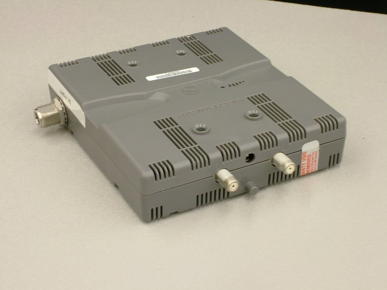
P3YSPOTCELL0102
Jun 05, 2012SpotCell 2500 XI
Equipment Class
TNB - Licensed Non-Broadcast Station Transmitter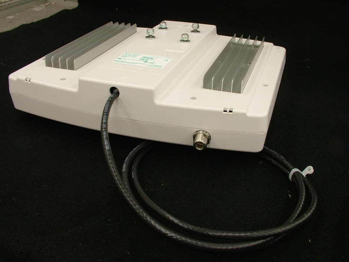
P3YSPOTCELL0101
Jun 05, 2012SpotCell 2500 XI
Equipment Class
TNB - Licensed Non-Broadcast Station Transmitter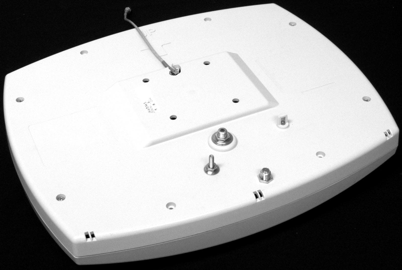
P3YSPOTCELL0013
Nov 02, 2004DU 1900 Full Band
Equipment Class
PCB - PCS Licensed Transmitter
P3YSPOTCELL0012
Nov 02, 2004Cell enhancer
Equipment Class
PCB - PCS Licensed Transmitter
P3YSPOTCELL0011
Aug 30, 2004Spotcell 612
Equipment Class
PCB - PCS Licensed Transmitter