P4U-MCT245MCT245
Kar-Tech, Inc.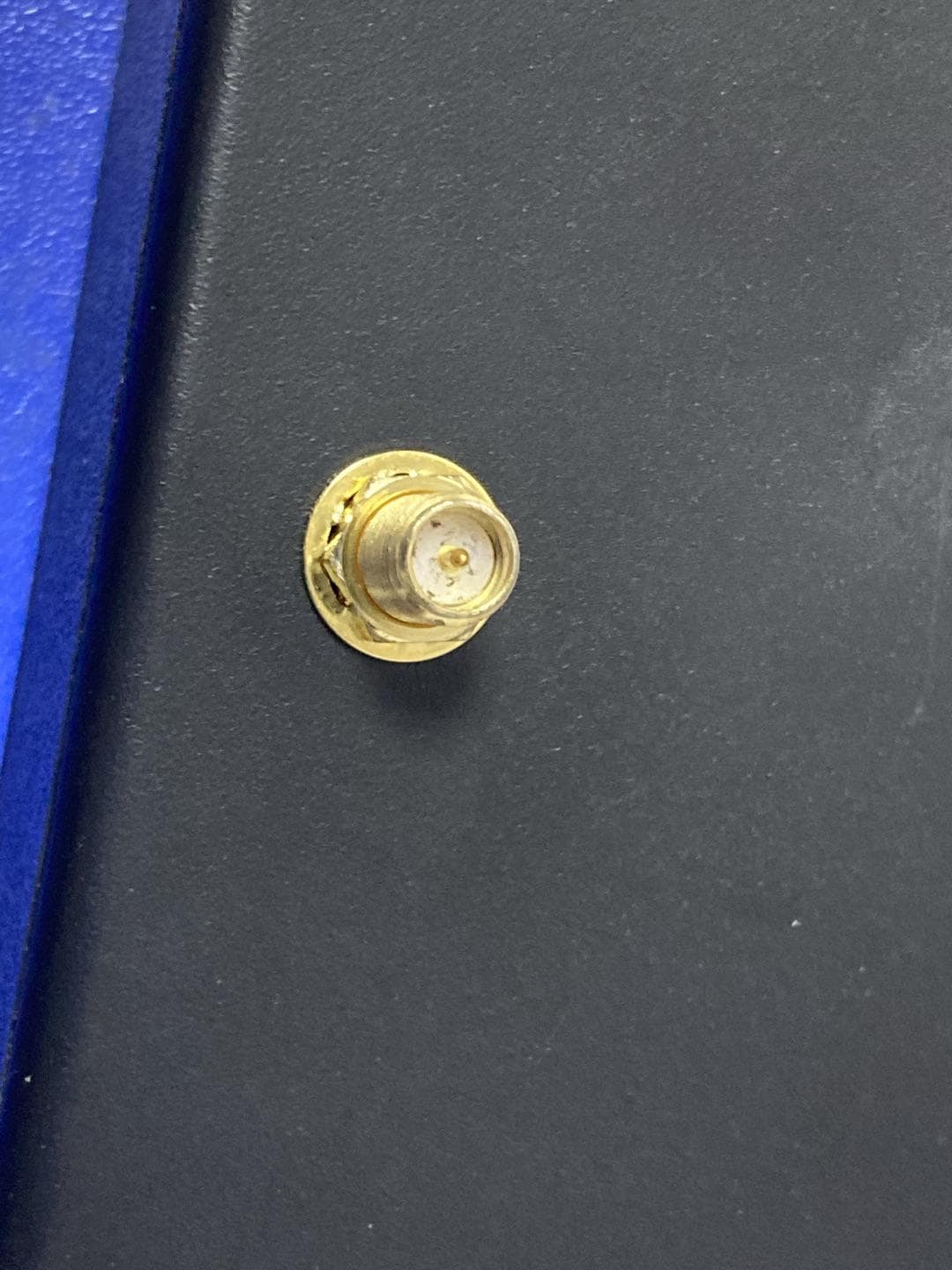
Click to zoom
Application Details
- Equipment Class
- DSS - Part 15 Spread Spectrum Transmitter
- Date of Grant
- Jul 23, 2020
- Application Purpose
- Original Equipment
- Date of Application
- Jul 23, 2020
- Equipment Note
- MCT245
- Frequency Range
- 2407.00000000 - 2470.00000000
- Company
- Kar-Tech, Inc.
- Country
- United States
Documents & Files
Document Text
Text extracted from the exhibit documents filed with the FCC. Open a document above to read the original.
Users Manual
MCT245 2.4GHz RECEIVER OEM INSTALLATION AND OPERATION MANUAL June 27, 2020 TH MCT245 RECEIVER 1 INDEX DESCRIPTION ........................................................................... 2 OPERATION .............................................................................. 2 INSTALLATION ......................................................................... 4 BEFORE APPLYING POWER! ...................................................... 5 TROUBLESHOOTING ................................................................. 6 TRANSCEIVER PICTORIAL ........................................................ 7 SPECIFICATIONS ...................................................................... 7 INSTRUCTION TO THE USER ..................................................... 8 INDUSTRY CANADA STATEMENTS ........................................... 10 MCT245 RECEIVER 2 DESCRIPTION The MCT245 is a frequency hopping spread spectrum transceiver unit, designed to be compatible with US (FCC Part 15.247), Canadian (RSS-210), EU(EN 60950-1, EN 300 328, EN 301 489) and Australian() regulations for license free use in the 2.4 GHz ISM band. The MCT245 is designed for mobile applications in accordance to Part 2.1091(b). The MCT245 remote control products are assembled by Kar- Tech, at Kar-Tech. There are no user serviceable parts on the MCT245 transceiver. The MCT245 is not designed for multiple antenna applications and should not be used to transmit simultaneously with any other transmitter. OPERATION The MCT245 is a radio Receiver product for the 2.4 GHz ISM bands. The Receiver microcontroller includes a CPU, GPI/O, a fully integrated frequency synthesizer, a power amplifier, a modulator and a receiver unit. The data received from antenna is sent to the microcontroller for processing. The MCT245 microcontroller monitors the input data, received data and controls outputs. The system data is sent to the RF processor and then to RF circuit, and then to the antenna. The microcontroller is responsible for the control of the entire communication. The MCT245 transceiver contains a DC regulator which generates a constant 1.8 VDC for the digital MCT245 RECEIVER 3 circuitry. The RF section runs on the 3.3V supply. The MCT245 uses Frequency Hopping Spread Spectrum that uses 16 channels for any hop mode, between 2.407GHZ and 2.470GHZ, with 1MHZ resolution. The receivers are matched to the transmitters to use the same channels and sequence as the transmitter’s signals. The MCT245 controls outputs which can operate relays, hydraulic valves, lights, or other similar load devices, according to customer requirements. Where Used Typical applications for the MCT245 are to controlling valves, relays and lights on agricultural equipment, construction equipment, and other similar equipment. MCT245 RECEIVER 4 INSTALLATION 1) Attach the external harness to the MCT245. 2) Assemble the MCT245 assembly into the Enclosure. 3) Place a label on the outside of the enclosure on the side. On the label, include the following: “FCC ID: P4U- MCT245” and “IC: 4534A- MCT245, CE” MCT245 RECEIVER 5 Application Requirements: A) Power the MCT245 Receiver with 9-30VDC nominal voltage, with peak current draw of 150mA. B) Assemble the MCT245, into a KAR-TECH Receiver enclosure. C) The MCT245 is to be installed only in mobile applications. See Part 2.1091 for definitions of mobile and fixed applications. D) Do not operate the MCT245 without an antenna. E)Documentations: In the host’s User Manual include the following: a. That there are no user serviceable parts in the radio product. They should not remove or install radio modules. b. The “Instructions To The User” section. c. The “Industry Canada Statement”. d. Include in the manual, “This device is granted for use in Mobile only configurations in which the antennas used for this transmitter must be installed to provide a separation distance of at least 20cm from all person and not be co- located with any other transmitters except in accordance with FCC and Industry Canada multi-transmitter product procedures.” BEFORE APPLYING POWER! Check power and ground for proper polarity. MCT245 RECEIVER 6 Read the rest of this manual. TROUBLESHOOTING There are no user serviceable parts in the MCT245 Receiver. Contact your KAR-TECH representative for further instructions or servicing. PARTS LIST PART NUMBER DESCRIPTION 022081A MCT245 RADIO TRANSCEIVER – REMOVEABLE ANTENNA There are no user-serviceable parts inside the transmitter or the receiver. Return the units for service. The information, specifications, and illustrations in this manual are those in effect at the time of printing. We reserve the right to change specifications or design at any time without notice. MCT245 RECEIVER 7 SPECIFICATIONS Equipment Class .............................. Part 15 Spread Spectrum Transmitter FCC ID ............................................................................. P4U- MCT245 ICC (Industry Canada Certification) ID .............................. 4534A- MCT245 TRANSCEIVER Power supply ......................................................................... 9-30VDC Operating Current ........................................................................ 48mA Operating temperature - Radio ....................................... -40 ̊C to +85 ̊C Storage temperature ................................................... -40 ̊C to +100 ̊C RF Frequency .................................................................... 2.4-2.48 GHz RF Transmit power (EIRP) .......................................................... 100 mW RF Receive Sensitivity ............................................................. -126 dBm MCT245 RECEIVER 8 INSTRUCTION TO THE USER This device complies with part 15 of the FCC Rules. Operation is subject to the following two conditions: (1) This device may not cause harmful interference, and (2) this device must accept any interference received, including interference that may cause undesired…
Text truncated - open the document above for the full version.
Cover Letter(s)
Kar-Tech,Inc. OfficeofEngineeringTechnology FederalCommunicationsCommission 7435OaklandMillsRoad Columbia,MD21046 USA Date:2020-07-21 Subject;RequestforConfidentiality FCCID:P4U-MCT245 ToWhomItMayConcern, PursuanttotheprovisionsoftheCommission’srulesTitle47Sections§0.457and§0.459,we arerequestingtheCommissiontowithholdthefollowingattachment(s)asconfidential documentsfrompublicdisclosureindefinitely. Thesedocumentscontaindetailedsystemandequipmentdescriptionsandareconsideredas proprietaryinformationinoperationoftheequipment.Thepublicdisclosureofthesedocuments mightbeharmfultoourcompanyandwouldgivecompetitorsanunfairadvantageinthemarket. SchematicDiagram BlockDiagram PartsList OperationalDescription Tune-upProcedure Inadditionaltoabovementioneddocuments,inordertocomplywiththemarketingregulations inTitle47CFR§2.803andtheimportationrulesinTitle47CFR§2.1204,whileensuringthat businesssensitiveinformationremainsconfidentialuntiltheactualmarketingofnewly authorizeddevices,werequestShortTermConfidentialityofthefollowingattachment(s); ExternalPhotos TestSetupPhotos InternalPhotos UserManual For45days,pursuanttoPublicNoticeDA04-1705. OR For180dayspursuanttoKDB726920D01. Itisourunderstandingthatallmeasurementtestreports,FCCIDlabelformatand correspondenceduringthecertificationreviewprocesscannotbegrantedasconfidential documentsandthisinformationwillbeavailableforpublicreviewoncethegrantofequipment authorizationisissued. Sincerely, Signature: Name:HassanKarbassi Title:President
Cover Letter(s)
Kar-Tech,Inc. AgentAuthorization Company:Kar-Tech,Inc. Address:111EnterpriseRoad,Delafield,WI53018 ProductName:MCT245 TradeMark:Kar-Tech ModelNumber(s):MCT245 FCCID:P4U-MCT245 WeauthorizeMiCOMLabsInc.,575BoulderCourt,Pleasanton,California94566,USA, toactonourbehalfonallmattersconcerningthecertificationofabovenamed equipment. WedeclarethatMiCOMLabsInc.isallowedtoforwardallinformationrelatedtothe approvalandcertificationofequipmenttotheregulatoryagenciesasrequiredandto discussanyissuesconcerningtheapprovalapplication.Anyandallactscarriedoutby MiCOMLabsonourbehalfshallhavethesameeffectasactsofourown. Signature:Date:2020-07-21 Name:HassanKarbassi Title:President Company:Kar-Tech,Inc.
External Photos
SHENZHENLCSCOMPLIANCETESTINGLABORATORYLTD.FCCID:P4U-MCT245IC:4534A-MCT245 8.EXTERIORPHOTOGRAPHS Fig.1 Fig.2 Antenna SHENZHENLCSCOMPLIANCETESTINGLABORATORYLTD.FCCID:P4U-MCT245IC:4534A-MCT245 Fig.3 Fig.4 SHENZHENLCSCOMPLIANCETESTINGLABORATORYLTD.FCCID:P4U-MCT245IC:4534A-MCT245 Fig.5 Fig.6 SHENZHENLCSCOMPLIANCETESTINGLABORATORYLTD.FCCID:P4U-MCT245IC:4534A-MCT245 Fig.7 Fig.8 SHENZHENLCSCOMPLIANCETESTINGLABORATORYLTD.FCCID:P4U-MCT245IC:4534A-MCT245 Fig.9
ID Label/Location Info
Introduction The MCT245 is a direct sequence spread spectrum transceiver product designed to be compatible wit h US (FCC Part 15.247) and Canadian (RSS-210) regulations for license free use in the 2.4GHz IS M band . The MCT245 trans ceiver is a stand-alone Kar-Tech remot e cont rol product. Theory of Operation The MCT245 is a radio transceiver product for the 2.4GHz ISM bands. The transceiver microcontroller includes a CPU, GPI/O, a fully integrated frequency synthesizer, a power amplifier, a modulator and a receiver unit. The MCT245 is primarily a receiver that communicates with a transmitter bidirectionally in a half-duplex fashion. The data received from antenna is sent to the RF microcontroller. The microcontroller takes the RF data to control outputs. The microcontroller also monitors input signals from local inputs. This data is sent to the RF processor and then is sent from the RF processor to RF circuit, and then to the antenna. The microcontroller is responsible for the control of the entire communication. The MCT245 transceiver contains a DC regulator which generates a constant 1.8 VDC for the digital circuitry. The RF section runs on the 3.3V supply. The receivers are matched to the transmitters to use the same channels and sequence as the transmitter’s signals. Specifications EUT : MCT245 Test Model : Power Supply MCT245 : DC 9-30V Hardware Version : A Software Version : A SRD : Operation frequency:2407MHz-2470MHz Channel Number : 64 Channels 2407~2467MHz for Hop one; 2408~2468MHz for Hop two; 2409~2469MHz for Hop three; 2410~2470MHz for Hop four; Channel Spacing : 1MHz Modulation Type : GFSK Antenna Description : Monopole antenna, 4dBi(Max.)
Internal Photos
SHENZHENLCSCOMPLIANCETESTINGLABORATORYLTD.FCCID:P4U-MCT245IC:4534A-MCT245 9.INTERIORPHOTOGRAPHS Fig.1 Fig.2 SHENZHENLCSCOMPLIANCETESTINGLABORATORYLTD.FCCID:P4U-MCT245IC:4534A-MCT245 Fig.3 Fig.4 SHENZHENLCSCOMPLIANCETESTINGLABORATORYLTD.FCCID:P4U-MCT245IC:4534A-MCT245 Fig.5 Fig.6
RF Exposure Info
SHENZHENLCSCOMPLIANCETESTINGLABORATORYLTD.FCCID:P4U-MCT245 Thisreportshallnotbereproducedexceptinfull,withoutthewrittenapprovalofShenzhenLCSComplianceTestingLaboratoryLtd. Page 1 of 4 MaximumPermissibleExposureReport 1.ProductInformation FCCID: P4U-MCT245 EUT: MCT245 TestModel: MCT245 PowerSupply: DC9-30V HardwareVersion: A SoftwareVersion: A SRD: Operationfrequency:2407MHz-2470MHz ChannelNumber: 64Channels 2407~2467MHzforHopone; 2408~2468MHzforHoptwo; 2409~2469MHzforHopthree; 2410~2470MHzforHopfour; ChannelSpacing: 1MHz ModulationType: GFSK AntennaDescription:Monopoleantenna,4dBi(Max.) Exposurecategory:Generalpopulation/uncontrolledenvironment EUTType:ProductionUnit DeviceType:MobileDevice SHENZHENLCSCOMPLIANCETESTINGLABORATORYLTD.FCCID:P4U-MCT245 Thisreportshallnotbereproducedexceptinfull,withoutthewrittenapprovalofShenzhenLCSComplianceTestingLaboratoryLtd. Page 2 of 4 2.EvaluationMethod SystemsoperatingundertheprovisionsofFCC47CFRsectionshallbeoperatedinamannerthatensuresthatthe publicisnotexposedtoradiofrequencyenergylevelinexcessoftheCommission’sguidelines. Inaccordancewith47CFRFCCPart2SubpartJ,section2.1091thisdevicehasbeendefinedasmobiledevicewhereby adistanceof0.2mnormallycanbemaintainedbetweentheuserandthedevice,andbelowRFPermissibleExposure limitshallcomplywith. InaccordancewithKDB447498D01forSimultaneoustransmissionMPEtestexclusionapplieswhenthesumoftheMPE ratiosforallsimultaneoustransmittingantennasincorporatedinahostdevice,basedonthecalculated/estimated, numericallymodelledormeasuredfieldstrengthsorpowerdensity,is≤1.0.TheMPEratioofeachantennais determinedattheminimumtestseparationdistancerequiredbytheoperatingconfigurationsandexposureconditions ofthehostdevice,accordingtotheratiooffieldstrengthsorpowerdensitytoMPElimit,atthetestfrequency.Either themaximumpeakorspatiallyaveragedresultsfrommeasurementsornumericalsimulationsmaybeusedto determinetheMPEratios.SpatialaveragingdoesnotapplywhenMPEisestimatedusingsimplecalculationsbasedon far-fieldplane-waveequivalentconditions.Theantennainstallationandoperatingrequirementsforthehostdevice mustmeettheminimumtestseparationdistancesrequiredbyallantennas,inbothstandaloneandsimultaneous transmissionoperations,tosatisfycompliance. 3.Limit 3.1ReferEvaluationMethod ANSIC95.1–1999:IEEEStandardforSafetyLevelswithRespecttoHumanExposuretoRadioFrequencyElectromagnetic Fields,3kHzto300GHz. FCCKDBpublication447498D01General1RFExposureGuidancev06:MobileandPortableDevicesRFExposure ProceduresandEquipmentAuthorizationPolicies. FCCCFR47part11.1310:Radiofrequencyradiationexposurelimits. FCCCFR47part22.1091:Radiofrequencyradiationexposureevaluation:mobiledevices 3.2Limit LimitsforMaximumPermissibleExposure(MPE)/ControlledExposure Frequency Range(MHz) ElectricField Strength(V/m) MagneticField Strength(A/m) PowerDensity (mW/cm²) AveragingTime (minute) LimitsforOccupational/ControlledExposure 0.3–3.0 3.0–30 30–300 300–1500 1500–100,000 614 1842/f 61.4 / / 1.63 4.89/f 0.163 / / (100)* (900/f 2 )* 1.0 f/300 5 6 6 6 6 6 LimitsforMaximumPermissibleExposure(MPE)/UncontrolledExposure Frequency Range(MHz) ElectricField Strength(V/m) MagneticField Strength(A/m) PowerDensity (mW/cm²) AveragingTime (minute) LimitsforOccupational/ControlledExposure 0.3–3.0 3.0–30 30–300 300–1500 1500–100,000 614 824/f 27.5 / / 1.63 2.19/f 0.073 / / (100)* (180/f 2 )* 0.2 f/1500 1.0 30 30 30 30 30 F=frequencyinMHz *=Plane-waveequivalentpowerdensity SHENZHENLCSCOMPLIANCETESTINGLABORATORYLTD.FCCID:P4U-MCT245 Thisreportshallnotbereproducedexceptinfull,withoutthewrittenapprovalofShenzhenLCSComplianceTestingLaboratoryLtd. Page 3 of 4 4.MPECalculationMethod PredicationofMPElimitatagivendistance Equationfrompage18ofOETBulletin65,Edition97-01 S=PG/4πR² Where:S=powerdensity P=powerinputtoantenna G=powergainoftheantennainthedirectionofinterestrelativetoanisotropicradiator R=distancetothecenterofradiationoftheantenna 5.AntennaInformation MCT245canonlyuseantennascertificatedasfollowsprovidedbymanufacturer; Antennatypeand antennanumber Operatefrequencyband Maximumantenna gain Notes Monopoleantenna2407MHz–2470MHz4.0dBiSRDANT 6.ConductedPower [SRDMaxPeakConductedPower] ModeChannelFrequency(MHz) MaxConductedPower (dBm) GFSK Low24079.752 Middle24388.950 High24705.798 7.ManufacturingTolerance [SRDMaxConductedPower] TestModeChannel MaxConductedPower (dBm) ANTMax.TuneUp Power(dBm) GFSK LCH9.7529.0±1.0 MCH8.9509.0±1.0 HCH5.7985.0±1.0 SHENZHENLCSCOMPLIANCETESTINGLABORATORYLTD.FCCID:P4U-MCT245 Thisreportshallnotbereproducedexceptinfull,withoutthewrittenapprovalofShenzhenLCSComplianceTestingLaboratoryLtd. Page 4 of 4 8.MeasurementResults 8.1StandaloneMPEEvaluation AsdeclaredbytheApplicant,theEUTisawirelessdeviceusedinafixapplication,atleast20cmfromanybodypartof theuserornearbypersons;fromthemaximumEUTRFoutputpower,theminimumseparationdistance,r=20cm,as wellasthegainoftheusedantennarefertoantennainformation,theRFpowerdensitycanbeobtained. ModulationType OutputpowerAntenna Gain (dBi) Antenna Gain (linear) MPE (mW/cm 2 ) MPE Limits (mW/cm 2 ) dBmmW GFSK10104.02.51190.0051.0 Remark: 1.Outputpowerincludingturn-uptolerance; 2.MPEevaluatedistanceis20cmfromusermanualprovidebymanufacturer; 3.WechoosethelowestfrequencyoperatetocalculateMPElimitashigherfrequencywillhavehigherMPElimits; 4.MPEvalues=PG/4πR². 8.Conclusion ThemeasurementresultscomplywiththeFCCLimitper47CFR2.1091fortheuncontrolledRFExposureofmobile device. ----------------THEENDOFREPORT---------------
Test Report
SHENZHENLCSCOMPLIANCETESTINGLABORATORYLTD.FCCID:P4U-MCT245ReportNo.:LCS200612010AEA Page1of24 AppendixA RFTestDataforSRD(ConductedMeasurement) ProductName:MCT245 TradeMark:Kar-Tech TestModel:MCT245 EnvironmentalConditions Temperature: 24.6 C RelativeHumidity:52.3% ATMPressure:100.0kPa TestEngineer:Diamond.Lu Supervisedby:Tom.Liu A.1MaxmumConductedPeakOutputPower ModeChannel.MaximumPeakOutputPower[dBm]Limit[dBm]Verdict GFSK LCH9.75221PASS MCH8.95021PASS HCH5.79821PASS TestGraphs GFSK/LCH SHENZHENLCSCOMPLIANCETESTINGLABORATORYLTD.FCCID:P4U-MCT245ReportNo.:LCS200612010AEA Page2of24 GFSK/MCH GFSK/HCH SHENZHENLCSCOMPLIANCETESTINGLABORATORYLTD.FCCID:P4U-MCT245ReportNo.:LCS200612010AEA Page3of24 A.220dBBandwidth ModeChannel.20dBBandwidth[MHz]Limit[MHz]Verdict GFSK LCH0.998NotSpecifiedPASS MCH0.755NotSpecifiedPASS HCH0.571NotSpecifiedPASS TestGraphs GFSK/LCH SHENZHENLCSCOMPLIANCETESTINGLABORATORYLTD.FCCID:P4U-MCT245ReportNo.:LCS200612010AEA Page4of24 GFSK/MCH GFSK/HCH SHENZHENLCSCOMPLIANCETESTINGLABORATORYLTD.FCCID:P4U-MCT245ReportNo.:LCS200612010AEA Page5of24 A.3CarrierFrequencySeparation ModeChannel.CarrierFrequencySeparation[MHz]Limit[MHz]Verdict GFSK HOP14.0140.665PASS HOP23.9960.665PASS HOP33.7020.665PASS HOP43.7440.665PASS TestGraphs GFSK/HOP1 SHENZHENLCSCOMPLIANCETESTINGLABORATORYLTD.FCCID:P4U-MCT245ReportNo.:LCS200612010AEA Page6of24 GFSK/HOP2 GFSK/HOP3 SHENZHENLCSCOMPLIANCETESTINGLABORATORYLTD.FCCID:P4U-MCT245ReportNo.:LCS200612010AEA Page7of24 GFSK/HOP4 A.4HoppingChannelNumber ModeChannel.NumberofHoppingChannel[N]Limit[N]Verdict GFSKHop116>=15PASS GFSKHop216>=15PASS GFSKHop316>=15PASS GFSKHop416>=15PASS SHENZHENLCSCOMPLIANCETESTINGLABORATORYLTD.FCCID:P4U-MCT245ReportNo.:LCS200612010AEA Page8of24 TestGraphs GFSK/HOP1 GFSK/HOP2 SHENZHENLCSCOMPLIANCETESTINGLABORATORYLTD.FCCID:P4U-MCT245ReportNo.:LCS200612010AEA Page9of24 GFSK/HOP3 GFSK/HOP4 SHENZHENLCSCOMPLIANCETESTINGLABORATORYLTD.FCCID:P4U-MCT245ReportNo.:LCS200612010AEA Page10of24 A.5DwellTime ModeChannel BurstWidth [ms/hop/ch] Total Hops[hop*ch] DwellTime[s]Limit[s]Verdict GFSK LCH 1.50130.01950.4 PASS MCH 1.50130.01950.4 PASS HCH 1.50130.01950.4 PASS TestGraphs GFSK/LCH SHENZHENLCSCOMPLIANCETESTINGLABORATORYLTD.FCCID:P4U-MCT245ReportNo.:LCS200612010AEA Page11of24 GFSK/MCH GFSK/HCH SHENZHENLCSCOMPLIANCETESTINGLABORATORYLTD.FCCID:P4U-MCT245ReportNo.:LCS200612010AEA Page12of24 A.6RFConductedSpuriousEmissions ModeChannelPref[dBm]Max.Level[dBm]Limit[dBm]Verdict GFSK LCH9.105 -23.206-10.90 PASS MCH8.35-27.163-11.65PASS HCH6.225-32.208-13.78PASS GFSK_LCH_Graphs Pref SHENZHENLCSCOMPLIANCETESTINGLABORATORYLTD.FCCID:P4U-MCT245ReportNo.:LCS200612010AEA Page13of24 Puw SHENZHENLCSCOMPLIANCETESTINGLABORATORYLTD.FCCID:P4U-MCT245ReportNo.:LCS200612010AEA Page14of24 GFSK_MCH_Graphs Pref Puw SHENZHENLCSCOMPLIANCETESTINGLABORATORYLTD.FCCID:P4U-MCT245ReportNo.:LCS200612010AEA Page15of24 GFSK_HCH_Graphs Pref Puw SHENZHENLCSCOMPLIANCETESTINGLABORATORYLTD.FCCID:P4U-MCT245ReportNo.:LCS200612010AEA Page16of24 A.7Band-edgeforRFConductedEmissions ModeChannel Carrier Frequency [MHz] Carrier Power [dBm] Frequency Hopping Max Spurious Level [dBm] Limit [dBm] Verdict GFSK LCH2407 9.255Off-48.522-10.78 PASS 8.826Hop1-45.980-11.17 PASS 8.932Hop2-48.658-11.17 PASS 8.515Hop3-48.630-11.49 PASS 8.678Hop4-47.479-11.28 PASS HCH2470 5.394Off-48.987-14.61 PASS 6.473Hop1-56.414-14.07 PASS 6.461Hop2-55.465-14.44 PASS 6.634Hop3-56.640-13.37 PASS 6.596Hop4-57.129-13.40 PASS SHENZHENLCSCOMPLIANCETESTINGLABORATORYLTD.FCCID:P4U-MCT245ReportNo.:LCS200612010AEA Page17of24 TestGraphs GFSK/LCH/NoHop GFSK/LCH/Hop1 SHENZHENLCSCOMPLIANCETESTINGLABORATORYLTD.FCCID:P4U-MCT245ReportNo.:LCS200612010AEA Page18of24 GFSK/LCH/Hop2 GFSK/LCH/Hop3 SHENZHENLCSCOMPLIANCETESTINGLABORATORYLTD.FCCID:P4U-MCT245ReportNo.:LCS200612010AEA Page19of24 GFSK/LCH/Hop4 GFSK/HCH/NoHop SHENZHENLCSCOMPLIANCETESTINGLABORATORYLTD.FCCID:P4U-MCT245ReportNo.:LCS200612010AEA Page20of24 GFSK/HCH/Hop1 GFSK/HCH/Hop2 SHENZHENLCSCOMPLIANCETESTINGLABORATORYLTD.FCCID:P4U-MCT245ReportNo.:LCS200612010AEA Page21of24 GFSK/HCH/Hop3 GFSK/HCH/Hop4 SHENZHENLCSCOMPLIANCETESTINGLABORATORYLTD.FCCID:P4U-MCT245ReportNo.:LCS200612010AEA Page22of24 A.8Restrict-bandband-edgemeasurements Test Mode HoppingFreq. Power [dBm] Gain Ground Factor E [dBuV/m] Detector Limit [dBuV/m] Verdict GFSK Off2310.0-48.4404.0050.79PEAK74PASS Off2310.0-61.3364.0037.89AV54PASS Off2390.0-45.2894.0053.94PEAK74PASS Off2390.0-58.9664.0040.26AV54PASS Off2483.5-49.4114.0049.82PEAK74PASS Off2483.5-61.0874.0038.14AV54PASS Off2500.0-49.0444.0050.19PEAK74PASS Off2500.0-61.1994.0038.03AV54PASS Restrict-bandband-edgemeasurements_2407_PEAK Restrict-bandband-edgemeasurements_2407_AV SHENZHENLCSCOMPLIANCETESTINGLABORATORYLTD.FCCID:P4U-MCT245ReportNo.:LCS200612010AEA Page23of24 Restrict-bandband-edgemeasurements_2470_PEAK Restrict-bandband-edgemeasurements_2470_AV SHENZHENLCSCOMPLIANCETESTINGLABORATORYLTD.FCCID:P4U-MCT245ReportNo.:LCS200612010AEA Page24of24
Test Report
SHENZHENLCSCOMPLIANCETESTINGLABORATORYLTD.FCCID:P4U-MCT245ReportNo.:LCS200612010AEA Thisreportshallnotbereproducedexceptinfull,withoutthewrittenapprovalofShenzhenLCSComplianceTestingLaboratoryLtd. Page1of32 FCCTESTREPORT FOR Kar-Tech,Inc. MCT245 TestModel:MCT245 Preparedfor:Kar-Tech,Inc. Address: 111EnterpriseRoad,P.O.Box180606,Delafield,Wisconsin 53018,UnitedStates Preparedby:ShenzhenLCSComplianceTestingLaboratoryLtd. Address: 101,201BldgA&301BldgC,JujiIndustrialParkShajingStreet, BaoanDistrict,Shenzhen,China Tel:(+86)755-82591330 Fax:(+86)755-82591332 Web:www.LCS-cert.com Mail:[email protected] Dateofreceiptoftestsample:June17,2020 Numberoftestedsamples:1 Serialnumber:Prototype DateofTest:June17,2020~June24,2020 DateofReport:June30,2020 SHENZHENLCSCOMPLIANCETESTINGLABORATORYLTD.FCCID:P4U-MCT245ReportNo.:LCS200612010AEA Thisreportshallnotbereproducedexceptinfull,withoutthewrittenapprovalofShenzhenLCSComplianceTestingLaboratoryLtd. Page2of32 FCCTESTREPORT FCCCFR47PART15C(15.247) ReportReferenceNo......................:LCS200612010AEA DateofIssue.......................................:June30,2020 TestingLaboratoryName..............:ShenzhenLCSComplianceTestingLaboratoryLtd. Address................................................: 101,201BldgA&301BldgC,JujiIndustrialParkShajingStreet, BaoanDistrict,Shenzhen,China TestingLocation/Procedure............ : FullapplicationofHarmonisedstandards■ PartialapplicationofHarmonisedstandards□ Otherstandardtestingmethod□ Applicant’sName.............................: Kar-Tech,Inc. Address................................................: 111EnterpriseRoad,P.O.Box180606,Delafield,Wisconsin 53018,UnitedStates TestSpecification Standard..............................................:FCCCFR47PART15C(15.247) TestReportFormNo.........................:LCSEMC-1.0 TRFOriginator....................................:ShenzhenLCSComplianceTestingLaboratoryLtd. MasterTRF.........................................:Dated2011-03 ShenzhenLCSComplianceTestingLaboratoryLtd.Allrightsreserved. Thispublicationmaybereproducedinwholeorinpartfornon-commercialpurposesaslongasthe ShenzhenLCSComplianceTestingLaboratoryLtd.isacknowledgedascopyrightownerandsourceofthe material.ShenzhenLCSComplianceTestingLaboratoryLtd.takesnoresponsibilityforandwillnot assumeliabilityfordamagesresultingfromthereader'sinterpretationofthereproducedmaterialduetoits placementandcontext. TestItemDescription.....................:MCT245 TradeMark..........................................:Kar-Tech TestModel...........................................:MCT245 Ratings.................................................: DC9-30V Result..................................................:Positive Compiledby:Supervisedby:Approvedby: JackLiu/Administrators JinWang/TechniqueprincipalGavinLiang/Manager SHENZHENLCSCOMPLIANCETESTINGLABORATORYLTD.FCCID:P4U-MCT245ReportNo.:LCS200612010AEA Thisreportshallnotbereproducedexceptinfull,withoutthewrittenapprovalofShenzhenLCSComplianceTestingLaboratoryLtd. Page3of32 FCC--TESTREPORT TestResult Positive Thetestreportmerelycorrespondstothetestsample. Itisnotpermittedtocopyextractsofthesetestresultwithoutthewrittenpermissionofthetestlaboratory. TestReportNo.:LCS200612010AEA June30,2020 Dateofissue TestModel...........................:MCT245 EUT.........................................:MCT245 Applicant...............................:Kar-Tech,Inc. Address..................................: 111EnterpriseRoad,P.O.Box180606,Delafield,Wisconsin 53018,UnitedStates Telephone...............................:/ Fax..........................................:/ Manufacturer........................:Kar-Tech,Inc. Address...................................: 111EnterpriseRoad,P.O.Box180606,Delafield,Wisconsin 53018,UnitedStates Telephone...............................:/ Fax..........................................:/ Factory...................................:/ Address...................................:/ Telephone...............................:/ Fax..........................................:/ SHENZHENLCSCOMPLIANCETESTINGLABORATORYLTD.FCCID:P4U-MCT245ReportNo.:LCS200612010AEA Thisreportshallnotbereproducedexceptinfull,withoutthewrittenapprovalofShenzhenLCSComplianceTestingLaboratoryLtd. Page4of32 RevisionHistory RevisionIssueDateRevisionsRevisedBy 000June30,2020InitialIssueGavinLiang SHENZHENLCSCOMPLIANCETESTINGLABORATORYLTD.FCCID:P4U-MCT245ReportNo.:LCS200612010AEA Thisreportshallnotbereproducedexceptinfull,withoutthewrittenapprovalofShenzhenLCSComplianceTestingLaboratoryLtd. Page5of32 TABLEOFCONTENTS DescriptionPage 1.GENERALINFORMATION.....................................................................................................6 1.1DescriptionofDevice(EUT)..........................................................................................................6 1.2SupportequipmentList...................................................................................................................7 1.3ExternalI/OCable...........................................................................................................................7 1.4DescriptionofTestFacility.............................................................................................................7 1.5StatementoftheMeasurementUncertainty................................................................................8 1.6MeasurementUncertainty..............................................................................................................8 1.7DescriptionofTestModes.............................................................................................................8 2.TESTMETHODOLOGY..........................................................................................................9 2.1EUTConfiguration...........................................................................................................................9 2.2EUTExercise.........................................................…
Text truncated - open the document above for the full version.
Test Setup Photos
SHENZHENLCSCOMPLIANCETESTINGLABORATORYLTD.FCCID:P4U-MCT245IC:4534A-MCT245 _______________________________________________________________________________________________ 7.TESTSETUPPHOTOGRAPHS PhotoofRadiatedEmissionsMeasurement Below1GHz Above1GHz
Contact Information
Applicant
Hassan Karbassi(President)
Technical Contact
Test Firm
Shenzhen LCS Compliance Testing Laboratory Ltd.Gavin Liang
Technical Specifications
| # | Rule Parts | Frequency Range | Power Output |
|---|---|---|---|
| 1 | 15C | 2.41 GHz - 2.47 GHz | 9.00 mW |
Other Applications from Kar-Tech, Inc.
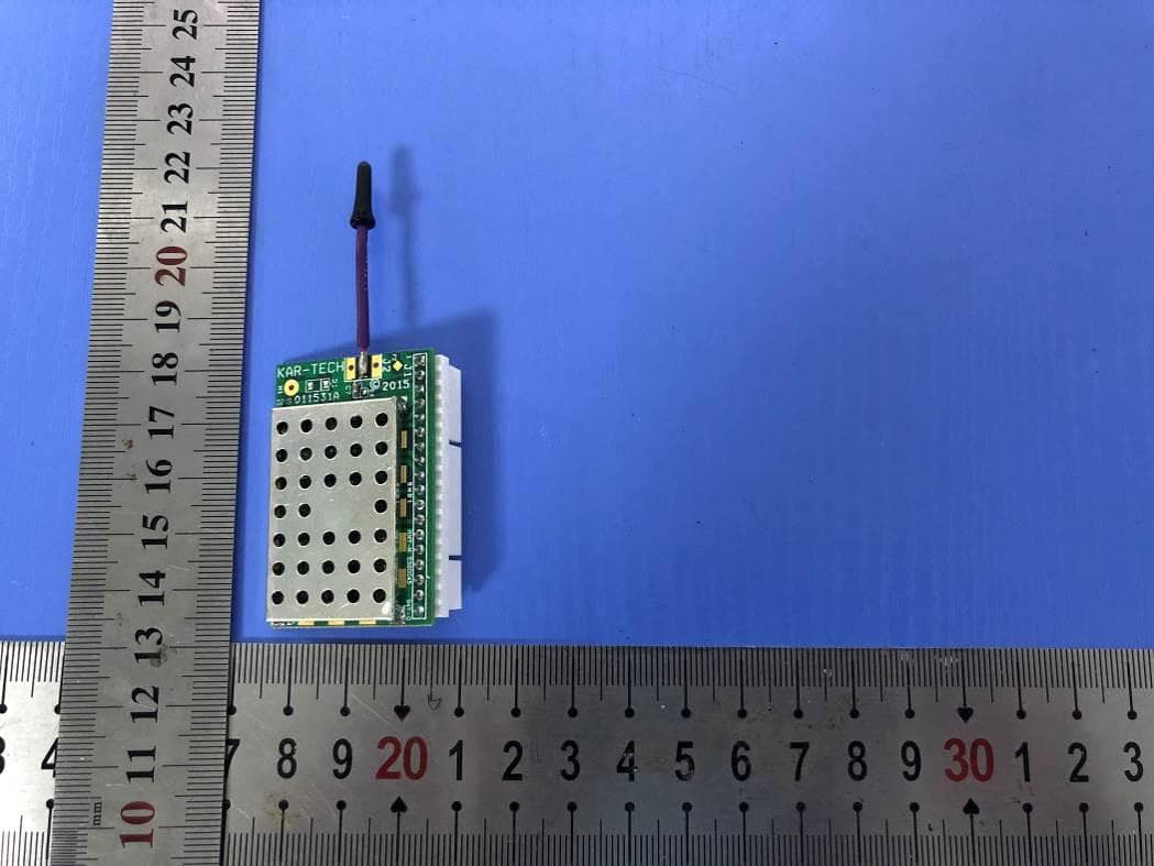
P4U-MCT247
Jul 29, 2020MCT247
Equipment Class
DSS - Part 15 Spread Spectrum Transmitter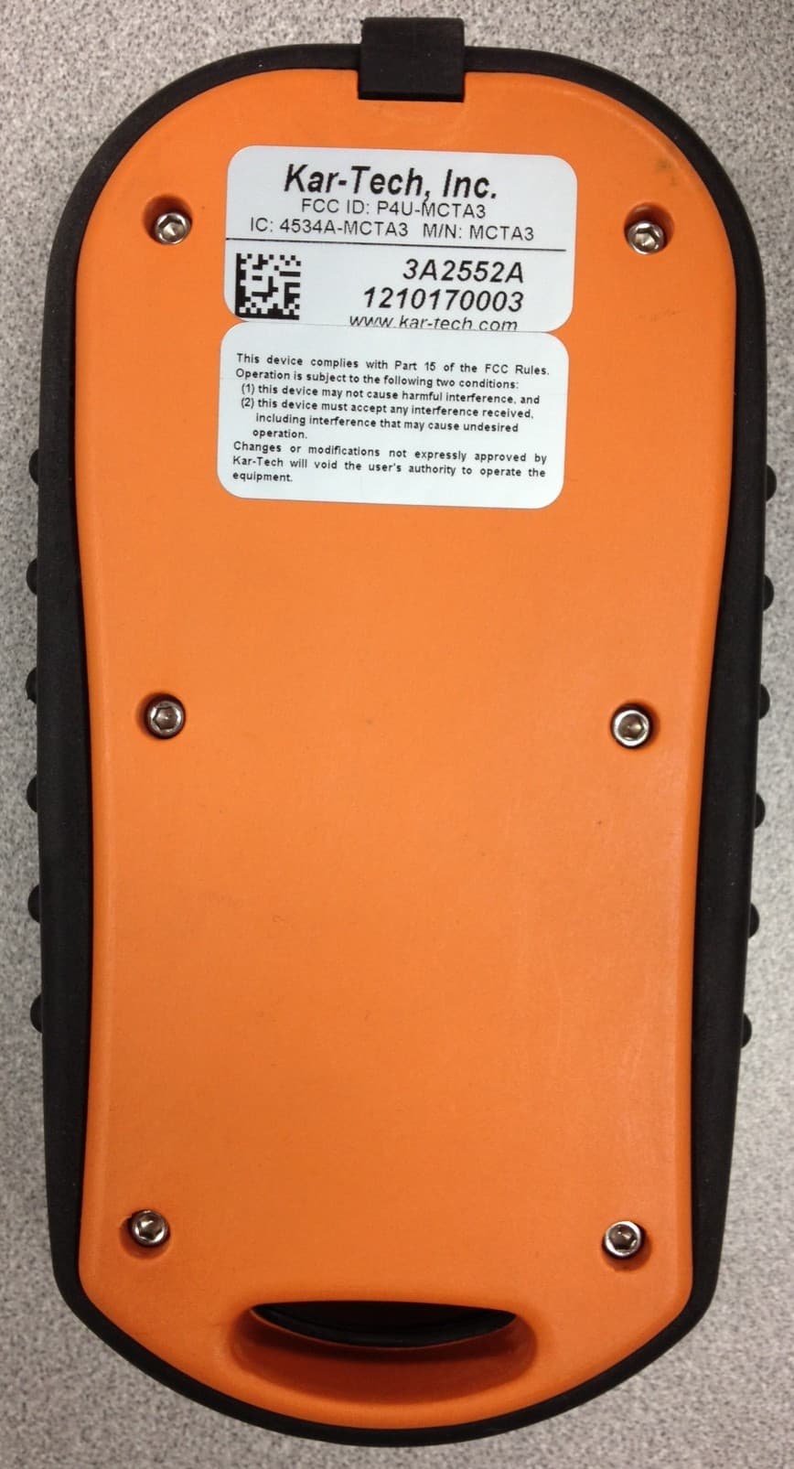
P4U-MCTA3
Nov 11, 2012REMOTE TRANSMITTER
Equipment Class
DXX - Part 15 Low Power Communication Device Transmitter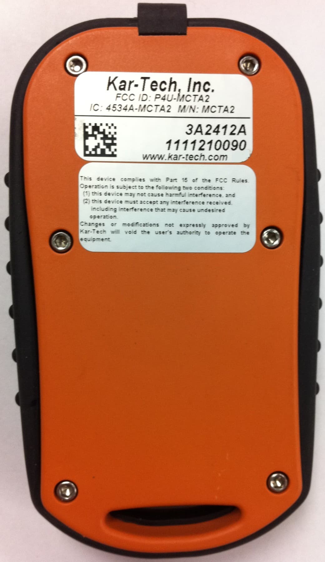
P4U-MCTA2
Feb 09, 2012REMOTE CONTROL
Equipment Class
DXX - Part 15 Low Power Communication Device Transmitter
P4U-MCTA1
May 16, 2011REMOTE CONTROL
Equipment Class
DXX - Part 15 Low Power Communication Device Transmitter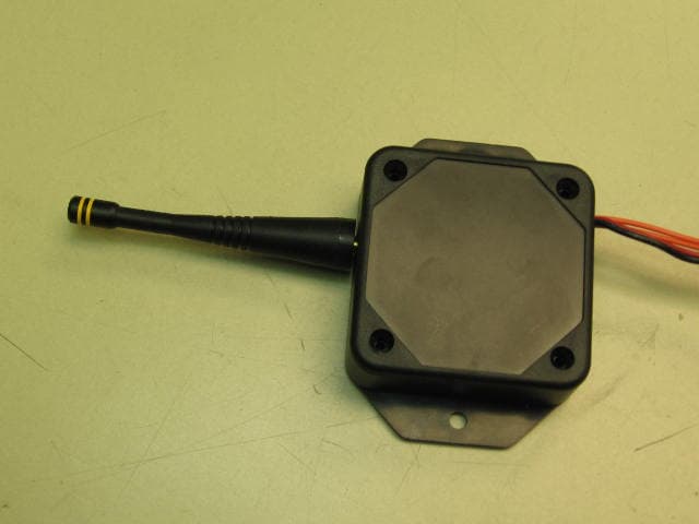
P4UMNTA2
Jun 04, 2006Mini Machine Mounted Transceiver
Equipment Class
DSS - Part 15 Spread Spectrum Transmitter