P4UMNTA2Mini Machine Mounted Transceiver
Kar-Tech, Inc.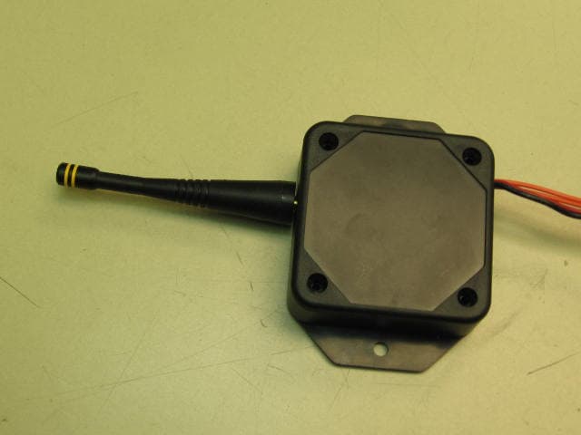
Click to zoom
Application Details
- Equipment Class
- DSS - Part 15 Spread Spectrum Transmitter
- Date of Grant
- Jun 04, 2006
- Application Purpose
- Original Equipment
- Date of Application
- Jun 04, 2006
- Equipment Note
- Mini Machine Mounted Transceiver
- Frequency Range
- 902.00000000 - 928.00000000
- Company
- Kar-Tech, Inc.
- Country
- United States
Documents & Files
Document Text
Text extracted from the exhibit documents filed with the FCC. Open a document above to read the original.
Users Manual
MNTA2 MINI REMOTE TM MINI REMOTE CONTROL SYSTEM PRELIMINARY USER MANUAL March 07, 2006 MINI REMOTE i INDEX Description ................................................................... 1 Installation ................................................................... 2 Before applying power ..................................................... 2 Routine Maintenance ....................................................... 3 Maintenance precautions .................................................. 3 Troubleshooting ............................................................. 3 Troubleshooting chart ................................................. 4 Specifications ................................................................ 5 Instructions to the User .................................................... 6 MINI REMOTE 1 DESCRIPTION: KAR-TECH's MINI REMOTE is a state of the art microprocessor based Radio Frequency (RF) remote control system designed to provide the machine operator with the ability to remotely operate equipment. The machine operator is still required to follow OSHA and other applicable standards when operating the equipment. This system is designed with Frequency Hopping Spread Spectrum (FHSS) Technology to eliminate the RF interference problem in Radio remote products. The control system consists of two major modules: the remote station (this unit), and a separate remote receiver (Digital Controller) sold separately. Each transmitter is preprogrammed with a special radio ID code. The receiver is programmed to respond only to the transmitter with the ID code for which it is set. This feature allows the equipment to work in wireless mode in close vicinity of each other without interfering with each other. In the event that a transmitter becomes damaged and a new one is needed, the receiver can be reprogrammed to respond to the new transmitter. MINI REMOTE 2 INSTALLATION: 1.Refer to the wiring chart for wiring connections. 3.When installing the unit, the main power should run from the battery, through a 20 amps fast blow fuse, to a power switch or relay; then into the receiver unit. For best results connect the receiver main power connections to the auxiliary terminal of the ignition switch, PTO switch, or ignition relay. Use 18 gauge or heavier wire. 4.All connections must be properly insulated to protect against shorts. BEFORE APPLYING POWER: 1.Check power and ground polarity. 2.Check wiring harness for possible shorts before connecting remote control to output devices (i.e., valves, relays) by checking each mating pin terminal. 3.Read the rest of this manual. MINI REMOTE 3 ROUTINE MAINTENANCE: 1. Clean transmitter and receiver regularly with a damp cloth and mild detergent. 2. Periodically check receiver antenna for tightness. 3. Inspect electrical wiring for wear points or other damage. Repair as required. 4. Inspect all connections for looseness or corrosion. Tighten and/or "seal" as necessary. MAINTENANCE PRECAUTIONS: When performing any inspection or maintenance work on the MINI REMOTE system, always exercise care to prevent injury to yourself and others or damage to the equipment. The following are general precautions that should be closely followed in carrying out any maintenance work. 1. Do not have hydraulic power available to the valves when performing electrical tests or downloading programs. 2. Never operate or test any function if any person is in an area where they could be hurt by being hit or squeezed by the hydraulic equipment. 3. Turn power off before connecting or disconnecting valve coils or other electrical loads. TROUBLESHOOTING: This section provides basic operator level troubleshooting for the MINI REMOTE system. If, after following these instructions, the system still does not function, check the hydraulic system then contact your KAR-TECH representative for further instructions or servicing. MINI REMOTE 4 TROUBLE SHOOTING CHART PROBLEM SOLUTION 1. No operation of all functions when a function switch is activated. 1. Check to see if a selector switch is in the proper position. 2. Check that unit power is on. 3. Check that receiver power is on. 4. Check vehicle wiring for power into the receiver. 5. Check LED status display for system status. 6. Check for proper grounding of vehicle's electrical circuit. 7. Check vehicle's hydraulic system 2. Certain functions do not work 1. Check the wiring connection from the receiver to the valve coil or the output function that does not work. 2. Check LED status display for system status. 3. Check vehicle's hydraulic system 4. Check vehicle's electrical system 3. Function operates intermittently. 1. Check for loose connections. 2. Check LED status display for system status. 3. Check receiver antenna for any damage and proper connection. 4. Check vehicle's hydraulic system MINI REMOTE 5 SPECIFICATIONS TRANSMITTER Power supply ........................................... +12V nominal, 9V to 35V transient Operating temperature - Radio ............................................ -40 ̊C to +85 ̊C Storage temperature........................................................ -40 ̊C to +100 ̊C Frequency ......................................................................... 902-928 MHz Transmit power (ERIP) ................................................................... 10 mW Vibration ............................................................................ 3G to 200Hz Shock ...........................................................................................50G There are no user-serviceable parts inside the Transmitter or the Receiver. Return the units to the KAR-TECH for service. Note: For operation with negative ground vehicles only. WARNING: The KAR-TECH MINI REMOTE must be operated in compliance with all applicable safety regulations, rules, and practices. Failure to follow required safety practices may result in death or serious injury. The information, specifications, and illustrations in t…
Text truncated - open the document above for the full version.
External Photos
EXTERNAL PHOTOS MINI MACHINE MOUNTED TRANSCEIVER
Internal Photos
INTERNAL PHOTOS MINI MACHINE MOUNTED TRANSCEIVER
RF Exposure Info
FCC ID: P4U-MNTA2 Report 3097359MIN-001M, May 2006 Page 18 of 51 3.6 RF Exposure Calculation, FCC 15.247(b)(5) The RF Exposure calculations are based on manufacturer specification that minimum distance from the antenna to operator (user) is 20cm. The RF Exposure can be calculated according to equation from OET Bulletin 65, Edition 97-01: S = PG/4*pi*R 2 , Where: S is Limits for Maximum Permissive Exposure (MPE) (mW/cm 2 ), P is Maximum Peak Power to Antenna (mW), G is Antenna Gain (numerical gain), R is Distance to the antenna radiation center (cm), must be below 20cm (FCC 2.1093) S = (F/1500)mW/cm 2 according to FCC 1.1310, where F (in MHz) from 300 to 1500MHz S = 902/1500 = 0.6 mW/cm 2 P = 9.36dBm = 8.63mW, G = 0.71dBi = 1.18 (numerical gain) R is calculated and = 1.2cm, within 20 cm
Test Report
FCC ID: P4U-MNTA2 Report 3097359MIN-001M, May 2006 Page 2 of 51 CONTENTS 1.0 GENERAL DESCRIPTION ............................................................................... 3 1.1 Related Submittals Grants ................................................................................... 3 1.2 Product Description........................................................................................... 3 1.3 Test Methodology............................................................................................. 3 1.4 Test Facility.................................................................................................... 3 2.0 SYSTEM TEST CONFIGURATION .................................................................... 4 2.1 Justification .................................................................................................... 4 2.2 EUT Setup ..................................................................................................... 4 2.3 EUT Exercising Software ................................................................................... 4 2.4 Special Accessories ........................................................................................... 4 2.5 Equipment Modification ..................................................................................... 4 2.6 Support Equipment List and Description.................................................................. 4 2.7 Test Configuration Block Diagrams ....................................................................... 5 3.0 TEST RESULTS ............................................................................................ 6 3.1 Maximum Peak Output Power, FCC 15.247(b)(3)...................................................... 7 3.2 Channel Frequency Separation, FCC 15.247(a)(1)..................................................... 11 3.3 20dB Bandwidth, FCC 15.247(a)(1)(i) ................................................................... 12 3.4 Time of Channel Occupancy, FCC 15.247(a)(1)(i) .................................................... 13 3.5 Number of Hopping Channels, FCC 15.247(b)(2) ..................................................... 15 3.6 RF Exposure Calculation, FCC 15.247(b)(5) ........................................................... 18 3.7 Band Edge Compliance, FCC 15.247(d)................................................................. 19 3.8 Spurious RF Conducted Emissions, FCC 15.247(d) ................................................... 23 3.9 Spurious Radiated Emissions, FCC 15.247(d), 15.205, 15.209 ..................................... 26 3.9.1 Duty Cycle Correction Factor Calculation, FCC 15.35......................................... 38 3.10 Conducted Emissions, FCC 15.207....................................................................... 40 3.11 Receiver Radiated Emissions, FCC 15.109 ............................................................. 42 3.12 Test Procedure................................................................................................ 49 3.13 Field Strength Calculation .................................................................................. 50 4.0 TEST EQUIPMENT .......................................................................................51 FCC ID: P4U-MNTA2 Report 3097359MIN-001M, May 2006 Page 3 of 51 1.0 GENERAL DESCRIPTION 1.1 Related Submittals Grants This is single application of the Kar-Tech Mini Machine Mounted Transceiver for Certification under FCC Part 15, Subpart C. There are no other simultaneous applications. 1.2 Product Description The Kar-Tech Mini Machine Mounted Transceiver and is a radio provides a wireless spread spectrum hopping communication within 902 - 928MHz frequency band under CFR 47:2005, Section 15.247. The intended use of the Transceiver is to generate a RF signal, deliver the signal to the antenna in order to communicate with the remote radios. The Mini Machine Mounted Transceiver is powered at 12VDC from the host unit. Antenna: ANT-916-CW-QW ¼-wave whip antenna, 0.71dBi gain, 50 Ohm impedance Sample Submitted: May 9, 2006 Test Work Started: May 15, 2006 Test Work Completed: May 18, 2006 1.3 Test Methodology Emission measurements were performed according to the procedures in ANSI C63.4-2003 and FCC Public Notice DA 00-705: March 30, 2000. All field strength radiated emissions measurements were performed in the semi-anechoic chamber, and for each scan, the procedure for maximizing emissions in were followed. All field strength radiated tests were performed at an antenna to EUT distance of 3 meters, unless stated otherwise in the "Justification Section" of this Application. 1.4 Test Facility The test site facility used to collect the radiated and conducted measurement data is located at 7250 Hudson Blvd., Suite 100, Oakdale, Minnesota. This test facility has been fully described in a report dated on December 2005 submitted to FCC. Please reference the site registration number: 90706, dated December 6, 2006. FCC ID: P4U-MNTA2 Report 3097359MIN-001M, May 2006 Page 4 of 51 2.0 SYSTEM TEST CONFIGURATION 2.1 Justification The Conducted Emissions at Mains testing was performed on when the EUT was powered through the BK Precision 1611A DC Power Supply. 2.2 EUT Setup For simplicity of testing, the transmitter was supplied with switches, which allowed run units at single channel at low, middle, and upper frequency in frequency range of 902 to 928MHz in transmitting mode, run units at single channel at low, middle, and upper frequency in frequency range of 902 to 928MHz in receiving mode, and run units in hopping transmitting mode. 2.3 EUT Exercising Software N/A 2.4 Special Accessories There are no special accessories necessary for compliance of these products. 2.5 Equipment Modification No modifications were installed during the testing. 2.6 Support Equipment List and Description BK Precision 1611A DC Power Supply FCC ID: P4U-MNTA2 Report 3097359MIN-001M, May 2006 Pa…
Text truncated - open the document above for the full version.
Test Setup Photos
CONFIGURATION PHOTOS Radiated Emissions Test Configuration Radiated Emissions Test Configuration Radiated Emissions Test Configuration Radiated Emissions Test Configuration
Contact Information
Applicant
Hassan Karbassi(President)
Technical Contact
Kar-Tech, Inc.Hassan Karbassi
[email protected]262-646-9444
111 Enterprise Road · Delafield, Wisconsin · United States
Non-Technical Contact
Kar-Tech, Inc.Hassan Karbassi
[email protected]262-646-9444
Test Firm
Intertek Testing ServicesUri Spector
Technical Specifications
| # | Rule Parts | Frequency Range | Power Output |
|---|---|---|---|
| 1 | 15C | 902 MHz - 928 MHz | 9.00 mW |
Other Applications from Kar-Tech, Inc.
P4U-MCT247
Jul 29, 2020MCT247
Equipment Class
DSS - Part 15 Spread Spectrum Transmitter
P4U-MCT245
Jul 23, 2020MCT245
Equipment Class
DSS - Part 15 Spread Spectrum Transmitter
P4U-MCTA3
Nov 11, 2012REMOTE TRANSMITTER
Equipment Class
DXX - Part 15 Low Power Communication Device Transmitter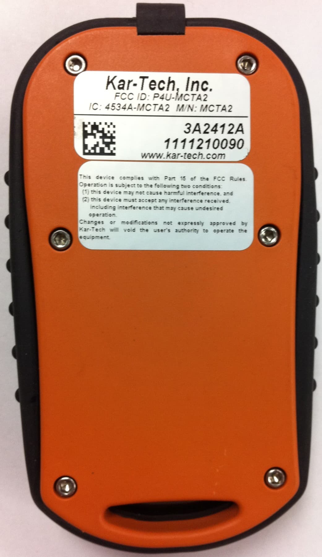
P4U-MCTA2
Feb 09, 2012REMOTE CONTROL
Equipment Class
DXX - Part 15 Low Power Communication Device Transmitter
P4U-MCTA1
May 16, 2011REMOTE CONTROL
Equipment Class
DXX - Part 15 Low Power Communication Device Transmitter