P4U-VRTSVersa Remote Transmitter Module
Kar-Tech, Inc.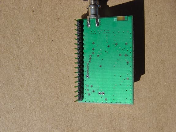
Click to zoom
Application Details
- Equipment Class
- DSS - Part 15 Spread Spectrum Transmitter
- Date of Grant
- Aug 06, 2003
- Application Purpose
- Original Equipment
- Date of Application
- Aug 06, 2003
- Equipment Note
- Versa Remote Transmitter Module
- Frequency Range
- 903.00000000 - 926.50000000
- Company
- Kar-Tech, Inc.
- Country
- United States
Documents & Files
Document Text
Text extracted from the exhibit documents filed with the FCC. Open a document above to read the original.
Users Manual
VERSA REMOTE TM FULL FEATURED REMOTE CONTROL SYSTEM OPERATIONS AND INSTALLATION MANUAL 3B0181CJ. July 25, 2003 VERSA REMOTE i INDEX Description ................................................................... 1-3 Installation ................................................................... 7 Before applying power ..................................................... 7 Transmitter and Receiver ID Code Programming ...................... 7-8 Wiring chart .................................................................. 9-11 Routine Maintenance ....................................................... 13 Maintenance precautions .................................................. 13 Troubleshooting ............................................................. 13 Troubleshooting chart ................................................. 14 Error Code chart........................................................ 15 Specifications ................................................................ 17-18 Instructions to the User .................................................... 19 VERSA REMOTE 1 DESCRIPTION: KAR-TECH's VERSA REMOTE is a state of the art microprocessor based Radio Frequency (RF) and Controller Area Network (CAN) remote control system designed to provide the machine operator with the ability to remotely operate equipment. The machine operator is still required to follow OSHA and other applicable standards when operating the equipment. This system is designed with Frequency Hopping Spread Spectrum (FHSS) Technology and Frequency Lock feature to eliminate the RF interference problem in Radio remote products. The control system consists of two major modules: the remote station (RF transmitter), and the Remote Receivers (Digital Controllers). Each transmitter is preprogrammed with a special radio ID code. The receiver is programmed to respond only to the transmitter with the ID code for which it is set. This feature allows the equipment to work in wireless mode in close vicinity of each other without interfering with each other. In the event that a transmitter becomes damaged and a new one is needed, the receiver can be reprogrammed to respond to the new transmitter. Please refer to TRANSMITTER AND RECEIVER ID CODE PROGRAMING section of this manual for additional information. The remote station has two LED indicators, the BATTERY and TRANSMIT indicators. The red BATTERY indicator starts blinking when the battery voltage drops below 9 volts and blinking speed increases while the voltage is decreasing. The transmitter is powered by a rechargeable battery and can be recharged by the +12 volt electrical system of the machine when connected to the machine by the CAN/charger cable or charger cable. An optional AC charger can be used to charge the battery. Both frequency and duration of use determine the operation time of the battery. Power is being used any time the transmitter power is on. To turn transmitter power off, turn off the power switch on the transmitter. To prolong the battery life and efficiency, the pendant should not VERSA REMOTE 2 be left on charge for a long period of time and should be discharged periodically. A complete charge can be achieved in 8 hour. To save battery life, the transmitter is designed with an auto shut down feature. This feature turns transmitter off when none of the switches or buttons is used for specified period. To turn transmitter on again, toggle the power switch to off, then on position. The transmitter is also able to communicate with the receiver via CAN (Controller Area Network) protocol. This is done by connecting the CAN cable to the transmitter. This feature is designed to allow the user to operate the machine in case of radio interference or discharged transmitter battery. OUTPUTS: There are sourcing on/off outputs and proportional outputs on the receiver module. Each output is designed with built in short circuit and overload protection. The on/off outputs are also designed with no load or broken wire status. These statuses are reported to the machine operator via the error code display in the receiver. Refer to the error code chart for a list of error codes. The Proportional outputs are current regulated and the minimum and maximum requited current as well as ramp for the proportional output is calibrated using a Palm Pilot tm . Each function is programmed for preset factory settings when shipped from Kar-Tech. Refer to factory setting table at the end of this manual. DISPLAY: The receiver is designed with an integrated 4-character alpha- numeric red LED Intelligent Display. This display is used to report the status of the outputs, radio communication, etc. to the machine operator. For additional information on error codes refer error code chart of this manual. VERSA REMOTE 3 VERSA REMOTE 4 VERSA REMOTE 5 VERSA REMOTE 6 VERSA REMOTE 7 INSTALLATION: 1.Refer to the wiring chart for wiring connections. 2.The receiver should be mounted on shock absorbing mounts. The receiver is best mounted in a protected location. 3.When installing the unit, the main power should run from the battery, through a 20 amps fast blow fuse, to a power switch or relay; then into the receiver unit. For best results connect the receiver main power connections to the auxiliary terminal of the ignition switch, PTO switch, or ignition relay. Use 18 gauge or heavier wire. 4.All connections must be properly insulated to protect against shorts. 5.Seal all connections with a non- conductive silicone grease to prevent against corrosion. BEFORE APPLYING POWER: 1.Check power and ground polarity. 2.Check wiring harness for possible shorts before connecting remote control to output devices (i.e., valves, relays) by checking each mating pin terminal. 3.Read the rest of this manual. TRANSMITTER AND RECEIVER ID CODE PROGRAMMING: Each transmitter is preprogrammed with a special radio ID code. The user can change the ID code by the following procedure. 1. Press the switch dow…
Text truncated - open the document above for the full version.
Attestation Statements
07-29-03 Request for a modular approval - FCC ID: P4U-VRTS Dear Application Examiner, The Kar-Tech, Inc. Versa Remote Transmitter Module Model: VRTS is seeking FCC authorization as a modular transmitter. The requirement of the FCC Public notice DA00-1407 are met. The following requirements are fulfilled: 1. The modular transmitter must have its own RF shielding The radio portion of the module is contained in its own RF shielding. See the external photos. 2. The modular transmitter must have buffered modulation/data inputs There is a microprocessor on the board that collects the information from the digital data collection module and sends this stream to the RF transmitter. 3. The modular transmitter must have its own power supply regulation The board used in this module includes its own 3.3 volt regulator on the main processor for regulating the power to the transmitter so regulation is not a problem. 4. The modular transmitter must comply with the antenna requirements of Section 15.203 The antenna is a reverse polarity SMA connector. The antenna will be provided with each module. 5. The modular transmitter must be tested in a stand-alone configuration The EUT was tested in a stand-alone configuration. The controller board that it is connected to is for collection of data only. 6. The modular transmitter must be labeled with its own FCC ID number The EUT will be labeled with its own FCC ID number. If the module is installed inside of an end-product, the label will not be visible. In this case the OEM customer will be instructed to how to apply the exterior label. 7. The modular transmitter must comply with any specific rule or operating requirements applicable to the transmitter and the manufacturer must provide adequate instructions along with the module to explain any such requirements. The EUT is compliant with all applicable FCC rules. Detail instructions are given in the Users Guide.
Operational Description
DESCRIPTION: FOR TESTING PURPOSES: The modular transmitter unit will be activated by pressing one of the buttons four push buttons connected to it. With the transciever in transmit mode, this will cause the transmitter to transmit data. If the transceiver is in receive mode, the buttons will cause the receiver to tune into a single channel. The transceiver module is activated by connecting any of the digital inputs to the on- board regulated +5V supply on the controller board. In the test system, one button on the transmitter operates output 1 on the receiver and broadcasts on 903 MHz, another operates output 2 on the receiver and broadcasts on 915 MHz, and the other operates output 3 on the receiver and broadcasts on 926 MHz. The fourth labelled button wil cause the transmitter to transmit in FHSS mode. The toggle switch selects transmit or receive mode. The transmitter control board operates on a +12V DC supply. FOR NORMAL OPERATION: The transmitter unit will be operated by switching the main power switch to the “ON” position and pressing one of the buttons on the transmitter enclosure. This will activate the transmitter on FHSS mode. Anytime the power is on but one of the buttons is not pressed, the transmitter will be powered down and the receiver will activate. The system hops to channel frequencies that are selected by a pseudorandomly ordered list of hopping frequencies. The input bandwidth of the receiver matches the hopping channel bandwidths of their corresponding transmitters, and shift frequencies in synchronization with the transmitted signals.
RF Exposure Info
19121 EL TORO ROAD, SILVERADO, CA 92676 TEL: (949) 589-0700 FAX: (949) 589-7700 Kar-Tech, Inc. Vera Remote Transmitter Module Model: VRTS FCC ID: P4U-VRTS The modular transmitter must comply with any applicable RF exposure requirements. The maximum measured power output is 12.3 dBm (17 mW), the maximum antenna gain is 3 dBi = numeric gain 1.995. The maximum permissible exposure is defined in 47 CFR 1.1310 as 0.6 mW/cm². The distance from the EUT's transmitting antenna where the exposure level reaches the maximum permitted level is calculated using the general equation: S = P*G /4pR² Smax = 0.6mW/cm², P = 17 mW, G= linear power gain relative to the isotropic radiator =1.995 (numeric gain), R = distance in cm Solving for R, the 0.6mW/cm² limit is reached in a distance of 2.1 cm to the transmitting antenna. The module has to be integrated in a way that the minimum distance of 2.1 cm is ensured.
Test Report
Report Number: C30818J1 FCC Part 15 Subpart B and FCC Section 15.247 Versa Remote Transmitter Module Model: VRTS Brea Division 114 Olinda Drive Brea, CA 92823 (714) 579-0500 Agoura Division 2337 Troutdale Drive Agoura, CA 91301 (818) 597-0600 Silverado Division 19121 El Toro Road Silverado, CA 92676 (949) 589-0700 Lake Forest Division 20621 Pascal Way Lake Forest, CA 92630 (949) 587-0400 Page 1 of 20 FCC PART 15, SUBPART B and C TEST REPORT for VERSA REMOTE TRANSMITTER MODULE MODEL: VRTS FCC ID: P4U-VRTS Prepared for KAR-TECH, INC. 111 ENTERPRISE ROAD DELAFIELD, WISCONSIN 53018 Prepared by:_____________________ CARLOS SANDOVAL Approved by:____________________ BRIAN VOEGELE COMPATIBLE ELECTRONICS INC. 19121 EL TORO ROAD LAKE FOREST, CALIFORNIA 92676 (949) 589-0700 DATE: AUGUST 19, 2003 REPORT APPENDICES TOTAL BODY A B C D E PAGES 20 2 2 2 10 54 90 This report shall not be reproduced except in full, without the written approval of Compatible Electronics. Report Number: C30818J1 FCC Part 15 Subpart B and FCC Section 15.247 Versa Remote Transmitter Module Model: VRTS Brea Division 114 Olinda Drive Brea, CA 92823 (714) 579-0500 Agoura Division 2337 Troutdale Drive Agoura, CA 91301 (818) 597-0600 Silverado Division 19121 El Toro Road Silverado, CA 92676 (949) 589-0700 Lake Forest Division 20621 Pascal Way Lake Forest, CA 92630 (949) 587-0400 Page 2 of 20 TABLE OF CONTENTS Section / Title PAGE GENERAL REPORT SUMMARY 4 SUMMARY OF TEST RESULTS 5 1. PURPOSE 6 2. ADMINISTRATIVE DATA 7 2.1 Location of Testing 7 2.2 Traceability Statement 7 2.3 Cognizant Personnel 7 2.4 Date Test Sample was Received 7 2.5 Disposition of the Test Sample 7 2.6 Abbreviations and Acronyms 7 3. APPLICABLE DOCUMENTS 8 4. DESCRIPTION OF TEST CONFIGURATION 9 4.1 Description of Test Configuration - EMI 9 4.1.1 Photograph of Test Configuration - EMI 9 4.1.2 Cable Construction and Termination 10 5. LISTS OF EUT, ACCESSORIES AND TEST EQUIPMENT 11 5.1 EUT and Accessory List 11 5.2 EMI Test Equipment 12 6. TEST SITE DESCRIPTION 13 6.1 Test Facility Description 13 6.2 EUT Mounting, Bonding and Grounding 13 7. CHARACTERISTICS OF THE TRANSMITTER 14 7.1 Transmitter Power 14 7.2 Channel Number and Frequencies 14 8. TEST PROCEDURES 15 8.1 RF Emissions 15 8.1.1 Radiated Emissions (Spurious and Harmonics) Test 15 8.2 20 dB Bandwidth 17 8.3 Peak Output Power 17 8.4 RF Antenna Conducted Test 17 8.5 RF Band Edges 18 8.6 Carrier Frequency Separation 18 8.7 Number of Hopping Frequencies 18 8.8 Average Time of Occupancy Test 19 9. CONCLUSIONS 20 Report Number: C30818J1 FCC Part 15 Subpart B and FCC Section 15.247 Versa Remote Transmitter Module Model: VRTS Brea Division 114 Olinda Drive Brea, CA 92823 (714) 579-0500 Agoura Division 2337 Troutdale Drive Agoura, CA 91301 (818) 597-0600 Silverado Division 19121 El Toro Road Silverado, CA 92676 (949) 589-0700 Lake Forest Division 20621 Pascal Way Lake Forest, CA 92630 (949) 587-0400 Page 3 of 20 LIST OF APPENDICES APPENDIX TITLE A Laboratory Recognitions B Modifications to the EUT C Additional Models Covered Under This Report D Diagrams, Charts, and Photos • Test Setup Diagrams • Radiated Emissions Photos • Antenna and Effective Gain Factors E Data Sheets LIST OF FIGURES FIGURE TITLE 1 Plot Map And Layout of Test Site Report Number: C30818J1 FCC Part 15 Subpart B and FCC Section 15.247 Versa Remote Transmitter Module Model: VRTS Brea Division 114 Olinda Drive Brea, CA 92823 (714) 579-0500 Agoura Division 2337 Troutdale Drive Agoura, CA 91301 (818) 597-0600 Silverado Division 19121 El Toro Road Silverado, CA 92676 (949) 589-0700 Lake Forest Division 20621 Pascal Way Lake Forest, CA 92630 (949) 587-0400 Page 4 of 20 GENERAL REPORT SUMMARY This electromagnetic emission test report is generated by Compatible Electronics Inc., which is an independent testing and consulting firm. The test report is based on testing performed by Compatible Electronics personnel according to the measurement procedures described in the test specifications given below and in the "Test Procedures" section of this report. The measurement data and conclusions appearing herein relate only to the sample tested and this report may not be reproduced without the written permission of Compatible Electronics, unless done so in full. This report must not be used to claim product endorsement by NVLAP or any other agency of the U.S. Government. Device Tested: Versa Remote Transmitter Module Model: VRTS S/N: N/A Product Description: See Expository Statement. Modifications: The EUT was not modified during the testing. Manufacturer: Kar-Tech Inc. 111 Enterprise Road Delafield, Wisconsin 53018 Test Dates: July 29, 30, 31, August 13, 15, and 18 2003 Test Specifications : EMI requirements CFR Title 47, Part 15, Subpart B; and Subpart C, sections 15.205, 15.209, and 15.247 Test Procedure: ANSI C63.4: 2001 FCC Public Notice (Document Number: DA 00-705) Test Deviations: The test procedure was not deviated from during the testing. Report Number: C30818J1 FCC Part 15 Subpart B and FCC Section 15.247 Versa Remote Transmitter Module Model: VRTS Brea Division 114 Olinda Drive Brea, CA 92823 (714) 579-0500 Agoura Division 2337 Troutdale Drive Agoura, CA 91301 (818) 597-0600 Silverado Division 19121 El Toro Road Silverado, CA 92676 (949) 589-0700 Lake Forest Division 20621 Pascal Way Lake Forest, CA 92630 (949) 587-0400 Page 5 of 20 SUMMARY OF TEST RESULTS TEST DESCRIPTION RESULTS 1 Spurious Radiated RF Emissions, 30 MHz – 1000 MHz Complies with the Class B limits of CFR Title 47, Part 15, Subpart B; and the limits of CFR Title 47, Part 15, Subpart C, section 15.209 2 Spurious Radiated RF Emissions, 10 kHz – 30 MHz and 1000 MHz – 10000 MHz Complies with the relevant requirements of CFR Title 47, Part 15, Subpart C, section 15.247(c) 3 Fundamental and Emissions produced by the intentional radiator in non-restricted bands, 10 kHz – 10 GHz Complies with the relevant requirements of CFR Title 47, Part 15, Subpart C, section 15.247(c) 4 Emissions produced by…
Text truncated - open the document above for the full version.
Contact Information
Applicant
Hassan Karbassi(President)
Technical Contact
Compatible ElectronicsCarlos Sandoval
[email protected]949-589-0700
19121 El Toro Road · Lake Forest, California · United States
Test Firm
Compatible ElectronicsBrian Voegele
Technical Specifications
| # | Rule Parts | Frequency Range | Power Output |
|---|---|---|---|
| 1 | 15C | 903 MHz - 926.5 MHz | 17.00 mW |
Other Applications from Kar-Tech, Inc.
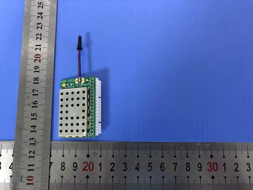
P4U-MCT247
Jul 29, 2020MCT247
Equipment Class
DSS - Part 15 Spread Spectrum Transmitter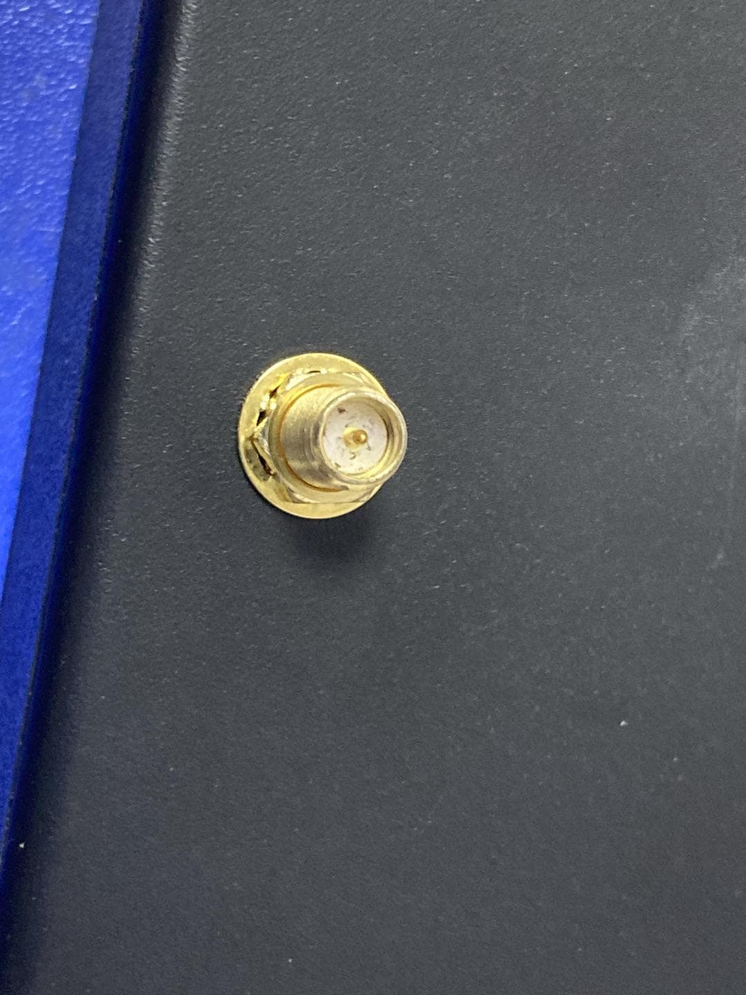
P4U-MCT245
Jul 23, 2020MCT245
Equipment Class
DSS - Part 15 Spread Spectrum Transmitter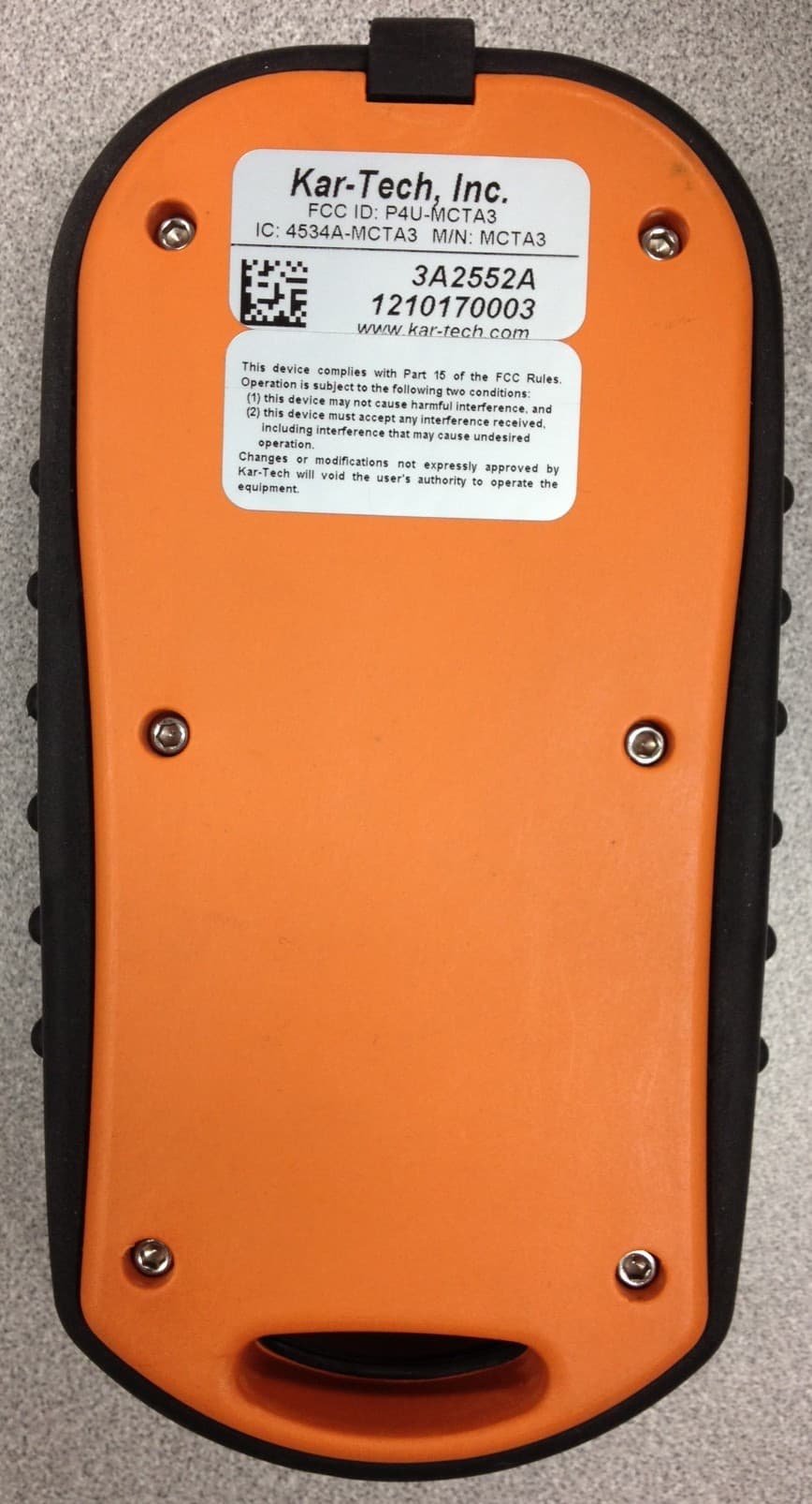
P4U-MCTA3
Nov 11, 2012REMOTE TRANSMITTER
Equipment Class
DXX - Part 15 Low Power Communication Device Transmitter
P4U-MCTA2
Feb 09, 2012REMOTE CONTROL
Equipment Class
DXX - Part 15 Low Power Communication Device Transmitter
P4U-MCTA1
May 16, 2011REMOTE CONTROL
Equipment Class
DXX - Part 15 Low Power Communication Device Transmitter