P4U-VRTXMVersa Remote Transmitter Module
Kar-Tech, Inc.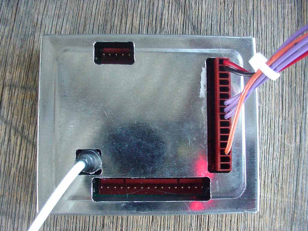
Click to zoom
Application Details
- Equipment Class
- DXX - Part 15 Low Power Communication Device Transmitter
- Date of Grant
- Jan 16, 2003
- Application Purpose
- Original Equipment
- Date of Application
- Jan 16, 2003
- Equipment Note
- Versa Remote Transmitter Module
- Frequency Range
- 903.30000000 - 921.30000000
- Company
- Kar-Tech, Inc.
- Country
- United States
Documents & Files
Document Text
Text extracted from the exhibit documents filed with the FCC. Open a document above to read the original.
Users Manual
VERSA REMOTE TM FULL FEATURED REMOTE CONTROL SYSTEM OPERATIONS AND INSTALLATION MANUAL 3B0181CJ. July 25, 2003 VERSA REMOTE i INDEX Description ................................................................... 1-3 Installation ................................................................... 7 Before applying power ..................................................... 7 Transmitter and Receiver ID Code Programming ...................... 7-8 Wiring chart .................................................................. 9-11 Routine Maintenance ....................................................... 13 Maintenance precautions .................................................. 13 Troubleshooting ............................................................. 13 Troubleshooting chart ................................................. 14 Error Code chart........................................................ 15 Specifications ................................................................ 17-18 Instructions to the User .................................................... 19 VERSA REMOTE 1 DESCRIPTION: KAR-TECH's VERSA REMOTE is a state of the art microprocessor based Radio Frequency (RF) and Controller Area Network (CAN) remote control system designed to provide the machine operator with the ability to remotely operate equipment. The machine operator is still required to follow OSHA and other applicable standards when operating the equipment. This system is designed with Frequency Hopping Spread Spectrum (FHSS) Technology and Frequency Lock feature to eliminate the RF interference problem in Radio remote products. The control system consists of two major modules: the remote station (RF transmitter), and the Remote Receivers (Digital Controllers). Each transmitter is preprogrammed with a special radio ID code. The receiver is programmed to respond only to the transmitter with the ID code for which it is set. This feature allows the equipment to work in wireless mode in close vicinity of each other without interfering with each other. In the event that a transmitter becomes damaged and a new one is needed, the receiver can be reprogrammed to respond to the new transmitter. Please refer to TRANSMITTER AND RECEIVER ID CODE PROGRAMING section of this manual for additional information. The remote station has two LED indicators, the BATTERY and TRANSMIT indicators. The red BATTERY indicator starts blinking when the battery voltage drops below 9 volts and blinking speed increases while the voltage is decreasing. The transmitter is powered by a rechargeable battery and can be recharged by the +12 volt electrical system of the machine when connected to the machine by the CAN/charger cable or charger cable. An optional AC charger can be used to charge the battery. Both frequency and duration of use determine the operation time of the battery. Power is being used any time the transmitter power is on. To turn transmitter power off, turn off the power switch on the transmitter. To prolong the battery life and efficiency, the pendant should not VERSA REMOTE 2 be left on charge for a long period of time and should be discharged periodically. A complete charge can be achieved in 8 hour. To save battery life, the transmitter is designed with an auto shut down feature. This feature turns transmitter off when none of the switches or buttons is used for specified period. To turn transmitter on again, toggle the power switch to off, then on position. The transmitter is also able to communicate with the receiver via CAN (Controller Area Network) protocol. This is done by connecting the CAN cable to the transmitter. This feature is designed to allow the user to operate the machine in case of radio interference or discharged transmitter battery. OUTPUTS: There are sourcing on/off outputs and proportional outputs on the receiver module. Each output is designed with built in short circuit and overload protection. The on/off outputs are also designed with no load or broken wire status. These statuses are reported to the machine operator via the error code display in the receiver. Refer to the error code chart for a list of error codes. The Proportional outputs are current regulated and the minimum and maximum requited current as well as ramp for the proportional output is calibrated using a Palm Pilot tm . Each function is programmed for preset factory settings when shipped from Kar-Tech. Refer to factory setting table at the end of this manual. DISPLAY: The receiver is designed with an integrated 4-character alpha- numeric red LED Intelligent Display. This display is used to report the status of the outputs, radio communication, etc. to the machine operator. For additional information on error codes refer error code chart of this manual. VERSA REMOTE 3 VERSA REMOTE 4 VERSA REMOTE 5 VERSA REMOTE 6 VERSA REMOTE 7 INSTALLATION: 1.Refer to the wiring chart for wiring connections. 2.The receiver should be mounted on shock absorbing mounts. The receiver is best mounted in a protected location. 3.When installing the unit, the main power should run from the battery, through a 20 amps fast blow fuse, to a power switch or relay; then into the receiver unit. For best results connect the receiver main power connections to the auxiliary terminal of the ignition switch, PTO switch, or ignition relay. Use 18 gauge or heavier wire. 4.All connections must be properly insulated to protect against shorts. 5.Seal all connections with a non- conductive silicone grease to prevent against corrosion. BEFORE APPLYING POWER: 1.Check power and ground polarity. 2.Check wiring harness for possible shorts before connecting remote control to output devices (i.e., valves, relays) by checking each mating pin terminal. 3.Read the rest of this manual. TRANSMITTER AND RECEIVER ID CODE PROGRAMMING: Each transmitter is preprogrammed with a special radio ID code. The user can change the ID code by the following procedure. 1. Press the switch dow…
Text truncated - open the document above for the full version.
Attestation Statements
12-03-2002 Request for a modular approval - FCC ID: P4U-VRTXM Dear Application Examiner, The Kar-Tech, Inc. Versa Remote Transmitter Module Model: VRTXM is seeking FCC authorization as a modular transmitter. The requirement of the FCC Public notice DA00-1407 are met. The following requirements are fulfilled: 1. The modular transmitter must have its own RF shielding The radio portion of the module is contained in its own RF shielding. See the external photos. 2. The modular transmitter must have buffered modulation/data inputs There is a microprocessor on the board that collects the information from the digital and analog inputs and sends this stream to the RF transmitter. 3. The modular transmitter must have its own power supply regulation The board used in this module includes its own 5 volt regulator regulating the power for the entire board so regulation is not a problem. 4. The modular transmitter must comply with the antenna requirements of Section 15.203 The antenna is a reverse polarity SMA connector. The antenna will be provided with each module. 5. The modular transmitter must be tested in a stand-alone configuration The EUT was tested in a stand-alone configuration. Only a DC Power supply to provide power and three buttons were wired to the module so that the low, middle, and high channel could be locked in. (Yellow Button = Low Channel, Red Button = Middle Channel, Green Button = High Channel). 6. The modular transmitter must be labeled with its own FCC ID number The EUT will be labeled with its own FCC ID number. If the module is installed inside of an end-product, the label will not be visible. In this case the OEM customer will be instructed to how to apply the exterior label. 7. The modular transmitter must comply with any specific rule or operating requirements applicable to the transmitter and the manufacturer must provide adequate instructions along with the module to explain any such requirements. The EUT is compliant with all applicable FCC rules. Detail instructions are given in the Users Guide.
Cover Letter(s)
114 OLINDA DRIVE • •• • BREA, CALIFORNIA 92823 • •• • (714) 579-0500 • •• • FAX (714) 579-1850 December 9, 2002 CETCB 114 Olinda Drive Brea, CA 92823 Subject: Request for Certification of the Kar-Tech, Inc. Versa Remote Transmitter Module Model: VRTXM FCC ID: P4U-VRTXM Gentlemen: We have enclosed a package for the certification of the Kar-Tech, Inc. Versa Remote Transmitter Module Model: VRTXM. We are requesting a Modular Approval. The list of requirements for a Modular Approval will be included in this application. We have enclosed the completed Form 731 with the applicable exhibits. If you have any questions or need any additional information, please give me a call at (714) 579-0500. Sincerely, Kyle Fujimoto Test Engineer
Cover Letter(s)
1 Scott McCutchan From: Scott McCutchan [[email protected]] Sent: Wednesday, January 08, 2003 3:30 PM To: [email protected] Subject: FCC ID: P4U-VRTXM Scott McCutchan.vcf Mr. Fujimoto, In order for processing of this application (FCC ID: P4U-VRTXM) to continue, the following issue(s) will have to be addressed: 1) The data sheets in the test report show that the fundamental emission was averaged. For transmitters operating under section 15.249, the quasi-peak value of the fundamental must comply with the limit. The item(s) indicated above must be submitted before processing can continue on the above referenced application. Failure to provide the requested information within 60 days of the original e-mail date may result in application dismissal and forfeiture of the filing fee. Also, please note that partial responses increase processing time and should not be submitted. Please upload your response to our electronic filing website using a correspondance number of "P4U-VRTXM-1". If you have any questions, feel free to contact me. Best regards, Scott McCutchan Operations Manager Compatible Electronics TCB (714) 579-1489 fax (714) 579-1850 http://www.celectronics.com Correspondence by Project Project Number: -1775081229 Correspondence Number Memo P4U-VRTXM-1 1) The data sheets in the test report show that the fundamental emission was averaged. For transmitters operating under section 15.249, the quasi-peak value of the fundamental must comply with the limit. Response: The test report has been revised so that the data sheet now reads quasi-peak for the fundamental readings. The readings were quasi-peaked but the column reading "average or quasi-peak" wasn't changed to show "QP" for the fundamental. Please see the revised test report -- note the front page has been scanned in because of errors with the digital signature that causes the report body to get corrupted when trying to sign.
Operational Description
DESCRIPTION: The modular transmitter unit will be activated by pressing one of the buttons connected to it. This will cause the transmitter to transmit data to the receiver. The receiver will decode the data and turn on an output. The transmitter module is activated by connecting any of the digital inputs to the on-board regulated +5V supply. The receivers are activated by applying power to the power leads of the receiver and activating an input on the transmitter. In the test system, the yellow button on the transmitter operates output 1 on the receiver and broadcasts on channel 0 (903.37 MHz), the red button operates output 2 on the receiver and broadcasts on channel 3 (909.37 MHz), and the green button operates output 3 on the receiver and broadcasts on channel 7 (921.37 MHz). Both receivers are programmed similiarly, in that a button on the transmitter will activate an output on the receivers. Each receiver has a load connected to output 1 and therefore will activate with the yellow button on the transmitter. All units will operate on a +12V DC supply.
Test Report
Report Number: B21202D1 FCC Part 15 Subpart B and FCC Section 15.249 Test Report VERSA Remote Transmitter Module Model: VRTXM 114 OLINDA DRIVE, BREA, CALIFORNIA 92823 PHONE: (714) 579-0500 FAX: (714) 579-1850 Page 2 of 16 TABLE OF CONTENTS Section / Title PAGE GENERAL REPORT SUMMARY 4 SUMMARY OF TEST RESULTS 4 1. PURPOSE 5 2. ADMINISTRATIVE DATA 6 2.1 Location of Testing 6 2.2 Traceability Statement 6 2.3 Cognizant Personnel 6 2.4 Date Test Sample was Received 6 2.5 Disposition of the Test Sample 6 2.6 Abbreviations and Acronyms 6 3. APPLICABLE DOCUMENTS 7 4. Description of Test Configuration 8 4.1 Description of Test Configuration - EMI 8 4.1.1 Cable Construction and Termination 9 5. LISTS OF EUT, ACCESSORIES AND TEST EQUIPMENT 10 5.1 EUT and Accessory List 10 5.2 EMI Test Equipment 11 6. TEST SITE DESCRIPTION 12 6.1 Test Facility Description 12 6.2 EUT Mounting, Bonding and Grounding 12 7. Test Procedures 13 7.1 Radiated Emissions (Spurious and Harmonics) Test 13 7.2 Band Edges 15 8. CONCLUSIONS 16 Report Number: B21202D1 FCC Part 15 Subpart B and FCC Section 15.249 Test Report VERSA Remote Transmitter Module Model: VRTXM 114 OLINDA DRIVE, BREA, CALIFORNIA 92823 PHONE: (714) 579-0500 FAX: (714) 579-1850 Page 3 of 16 LIST OF APPENDICES APPENDIX TITLE A Laboratory Recognitions B Modifications to the EUT C Additional Models Covered Under This Report D Diagrams, Charts, and Photos • Test Setup Diagrams • Radiated Emissions Photos • Antenna and Effective Gain Factors E Data Sheets LIST OF FIGURES FIGURE TITLE 1 Plot Map And Layout of Test Site Report Number: B21202D1 FCC Part 15 Subpart B and FCC Section 15.249 Test Report VERSA Remote Transmitter Module Model: VRTXM 114 OLINDA DRIVE, BREA, CALIFORNIA 92823 PHONE: (714) 579-0500 FAX: (714) 579-1850 Page 4 of 16 GENERAL REPORT SUMMARY This electromagnetic emission test report is generated by Compatible Electronics Inc., which is an independent testing and consulting firm. The test report is based on testing performed by Compatible Electronics personnel according to the measurement procedures described in the test specifications given below and in the "Test Procedures" section of this report. The measurement data and conclusions appearing herein relate only to the sample tested and this report may not be reproduced without the written permission of Compatible Electronics, unless done so in full. This report must not be used to claim product endorsement by NVLAP or any other agency of the U.S. Government. Device Tested: Versa Remote Tx Module Model: VRTXM S/N: N/A Product Description: See Expository Statement. Modifications: The EUT was not modified during the testing. Manufacturer: Kar-Tech, Inc. 111 Enterprise Road Delafield, Wisconsin 53018 Test Date: December 2, 2002 Test Specifications : EMI requirements CFR Title 47, Part 15 Subpart B; and Subpart C, Sections 15.205, 15.209, and 15.249 Test Procedure: ANSI C63.4: 1992 Test Deviations: The test procedure was not deviated from during the testing. SUMMARY OF TEST RESULTS TEST DESCRIPTION RESULTS 1 Conducted RF Emissions, 450 kHz - 30 MHz This test was not performed because the EUT operates on DC power only and cannot be plugged into the AC public mains. 2 Radiated RF Emissions, 10 kHz - 9300 MHz Complies with the Class B limits of CFR Title 47, Part 15, Subpart B; and Subpart C, sections 15.205, 15.209, and 15.249. Report Number: B21202D1 FCC Part 15 Subpart B and FCC Section 15.249 Test Report VERSA Remote Transmitter Module Model: VRTXM 114 OLINDA DRIVE, BREA, CALIFORNIA 92823 PHONE: (714) 579-0500 FAX: (714) 579-1850 Page 5 of 16 1. PURPOSE This document is a qualification test report based on the Electromagnetic Interference (EMI) tests performed on the Versa Remote Tx Module Model: VRTXM. The EMI measurements were performed according to the measurement procedure described in ANSI C63.4: 1992. The tests were performed in order to determine whether the electromagnetic emissions from the equipment under test, referred to as EUT hereafter, are within the Class B specification limits defined by CFR Title 47, Part 15, Subpart B; and Subpart C, sections 15.205, 15.209, and 15.249. Report Number: B21202D1 FCC Part 15 Subpart B and FCC Section 15.249 Test Report VERSA Remote Transmitter Module Model: VRTXM 114 OLINDA DRIVE, BREA, CALIFORNIA 92823 PHONE: (714) 579-0500 FAX: (714) 579-1850 Page 6 of 16 2. ADMINISTRATIVE DATA 2.1 Location of Testing The EMI tests described herein were performed at the test facility of Compatible Electronics, 114 Olinda Drive, Brea, California 92823. 2.2 Traceability Statement The calibration certificates of all test equipment used during the test are on file at the location of the test. The calibration is traceable to the National Institute of Standards and Technology (NIST) . 2.3 Cognizant Personnel Kar-Tech, Inc. Aaron Oestreich General Manager Compatible Electronics, Inc. Kyle Fujimoto Test Engineer Michael Christensen Test Engineer 2.4 Date Test Sample was Received The test sample was received on November 27, 2002. 2.5 Disposition of the Test Sample The sample has not been returned to Kar-Tech, Inc. as of December 5, 2002. 2.6 Abbreviations and Acronyms The following abbreviations and acronyms may be used in this document. RF Radio Frequency EMI Electromagnetic Interference EUT Equipment Under Test P/N Part Number S/N Serial Number HP Hewlett Packard ITE Information Technology Equipment CML Corrected Meter Limit LISN Line Impedance Stabilization Network Report Number: B21202D1 FCC Part 15 Subpart B and FCC Section 15.249 Test Report VERSA Remote Transmitter Module Model: VRTXM 114 OLINDA DRIVE, BREA, CALIFORNIA 92823 PHONE: (714) 579-0500 FAX: (714) 579-1850 Page 7 of 16 3. APPLICABLE DOCUMENTS The following documents are referenced or used in the preparation of this EMI Test Report. SPEC TITLE CFR Title 47, Part 15 FCC Rules – Radio frequency devices (including digital devices) ANSI C63.4 1992 Methods of measurement of radio-noise emissions from low-voltage e…
Text truncated - open the document above for the full version.
Contact Information
Applicant
Hassan Karbassi(President)
Technical Contact
Compatible ElectronicsKyle Fujimoto
[email protected]714-579-0500
114 Olinda Drive · Brea, California · United States
Test Firm
Compatible ElectronicsScott McCutchan
714-579-0500Fax: 714-579-1850
Technical Specifications
| # | Rule Parts | Frequency Range | Power Output |
|---|---|---|---|
| 1 | 15C | 903.3 MHz - 921.3 MHz | - |
Other Applications from Kar-Tech, Inc.
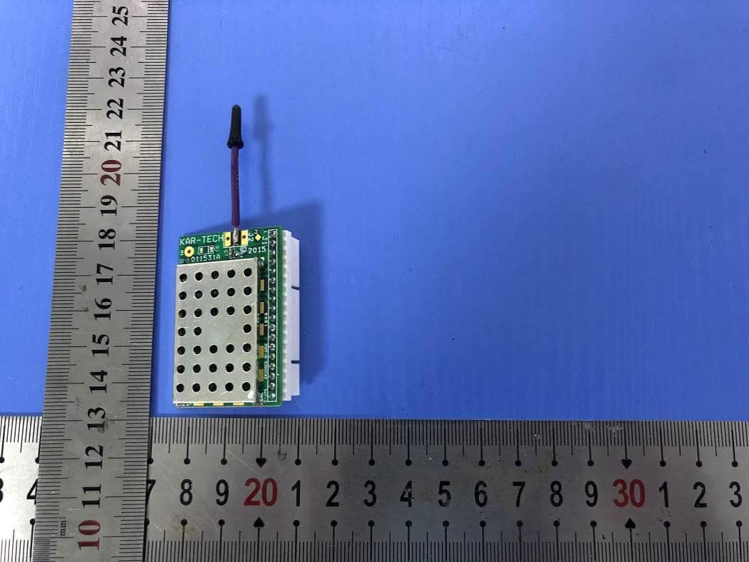
P4U-MCT247
Jul 29, 2020MCT247
Equipment Class
DSS - Part 15 Spread Spectrum Transmitter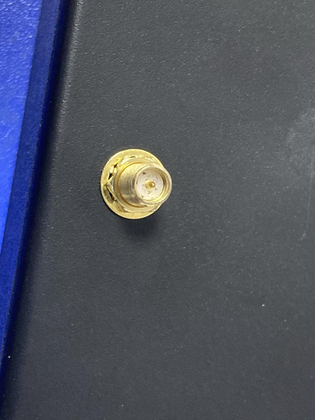
P4U-MCT245
Jul 23, 2020MCT245
Equipment Class
DSS - Part 15 Spread Spectrum Transmitter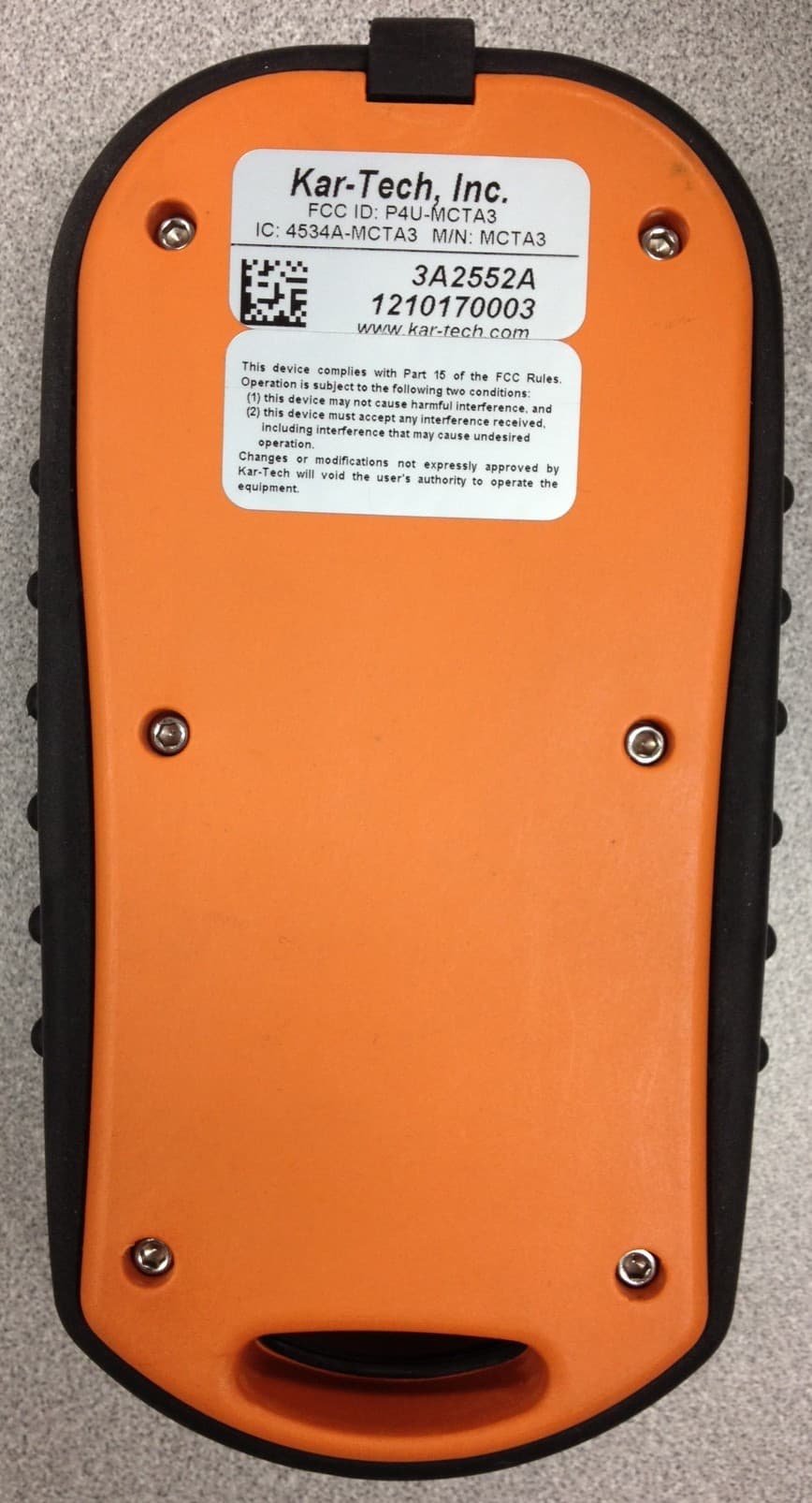
P4U-MCTA3
Nov 11, 2012REMOTE TRANSMITTER
Equipment Class
DXX - Part 15 Low Power Communication Device Transmitter
P4U-MCTA2
Feb 09, 2012REMOTE CONTROL
Equipment Class
DXX - Part 15 Low Power Communication Device Transmitter
P4U-MCTA1
May 16, 2011REMOTE CONTROL
Equipment Class
DXX - Part 15 Low Power Communication Device Transmitter