P6I-COPYCAM203COPYCAM
Polyvision Corporation, Interactive Products Group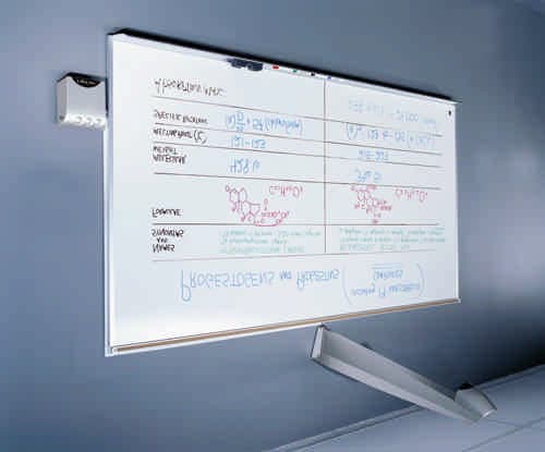
Click to zoom
Application Details
- Equipment Class
- DTS - Digital Transmission System
- Date of Grant
- Oct 15, 2002
- Application Purpose
- Original Equipment
- Date of Application
- Oct 15, 2002
- Equipment Note
- COPYCAM
- Frequency Range
- 2402.00000000 - 2480.00000000
- Country
- United States
Documents & Files
Document Text
Text extracted from the exhibit documents filed with the FCC. Open a document above to read the original.
Users Manual
Exhibit J: User Manual FCC ID: P6I-COPYCAM203 Part number 370-0111-01 ©2002 PolyVision Corporation All rights reserved Printed in USA User Guide Userguide_RevA_4.fm Page -1 Friday, January 18, 2002 11:07 AM Information in this document is subject to change without notice. Reproduction in any manner without written permission of PolyVision Corporation is forbidden. PolyVision Corporation reserves the right to make changes in product design, or detail, and to discontinue any product or material without notice. CopyCam is a trademark of PolyVision Corporation, a Steelcase Company. The Bluetooth trademarks are owned by Bluetooth SIG, Inc., USA. Userguide_RevA_4.fm Page 0 Friday, January 18, 2002 11:07 AM 1 TABLE OF CONTENTS Welcome to CopyCam . . . . . . . . . . . . . . . . . . . . . . . . . . . . . . . . . . . . . . . . 2 CopyCam Quick Start . . . . . . . . . . . . . . . . . . . . . . . . . . . . . . . . . . . . . . . . 3 What to Expect . . . . . . . . . . . . . . . . . . . . . . . . . . . . . . . . . . . . . . . . 3 CopyCam Quick Start . . . . . . . . . . . . . . . . . . . . . . . . . . . . . . . . . . . . . . . . 3 Three Ways to Make Copies. . . . . . . . . . . . . . . . . . . . . . . . . . . . . . . . 4 What You Can Copy . . . . . . . . . . . . . . . . . . . . . . . . . . . . . . . . . . . . 4 What You Can’t Copy . . . . . . . . . . . . . . . . . . . . . . . . . . . . . . . . . . . 4 Copying to the Printer . . . . . . . . . . . . . . . . . . . . . . . . . . . . . . . . . . . . 4 Copying to a Floppy Diskette . . . . . . . . . . . . . . . . . . . . . . . . . . . . . . . 5 Copying to the Web . . . . . . . . . . . . . . . . . . . . . . . . . . . . . . . . . . . . . . 7 Copying in any Combination . . . . . . . . . . . . . . . . . . . . . . . . . . . . . . . 8 The CopyCam Web Server . . . . . . . . . . . . . . . . . . . . . . . . . . . . . . . . . . . . .9 Accessing Your CopyCam Web Server. . . . . . . . . . . . . . . . . . . . . . . . 9 Using the Saved Shots Tab . . . . . . . . . . . . . . . . . . . . . . . . . . . . . . . 10 Saving Copies to your Hard Disk. . . . . . . . . . . . . . . . . . . . . . . . . 11 Printing From the Web . . . . . . . . . . . . . . . . . . . . . . . . . . . . . . . . . 11 Using the Settings Tab . . . . . . . . . . . . . . . . . . . . . . . . . . . . . . . . . . . 12 Using the Camera Info Tab. . . . . . . . . . . . . . . . . . . . . . . . . . . . . . . . 16 Changing Printers . . . . . . . . . . . . . . . . . . . . . . . . . . . . . . . . . . . . . . . 18 CopyCam Maintenance . . . . . . . . . . . . . . . . . . . . . . . . . . . . . . . . . . . . . . 23 Cleaning . . . . . . . . . . . . . . . . . . . . . . . . . . . . . . . . . . . . . . . . . . . . . . 23 Camera Arm Lens . . . . . . . . . . . . . . . . . . . . . . . . . . . . . . . . . . . . . . . 23 Web Site Maintenance. . . . . . . . . . . . . . . . . . . . . . . . . . . . . . . . . . . 23 Printer . . . . . . . . . . . . . . . . . . . . . . . . . . . . . . . . . . . . . . . . . . . . . . . . 23 Troubleshooting . . . . . . . . . . . . . . . . . . . . . . . . . . . . . . . . . . . . . . . . . . . 24 LED and Voice Status Messages . . . . . . . . . . . . . . . . . . . . . . . . . . .26 LED Status Indicators. . . . . . . . . . . . . . . . . . . . . . . . . . . . . . . . . .26 Voice Messages . . . . . . . . . . . . . . . . . . . . . . . . . . . . . . . . . . . . . .26 Userguide_RevA_4.fm Page 1 Friday, January 18, 2002 11:07 AM 2WELCOME TO COPYCAM WELCOME TO COPYCAM Welcome to CopyCam, your quick and easy tool to capture information from a whiteboard or chalkboard. This manual provides instructions for operating your CopyCam. Refer to the CopyCam Installation Guide for installation instructions. Camera arm Color printer Control pad with floppy drive Userguide_RevA_4.fm Page 2 Friday, January 18, 2002 11:07 AM COPYCAM QUICK START3 COPYCAM QUICK START Step 1: Write on the board. Step 2: Press a button on the control pad. Step 3: You’re done! CopyCam captures the board and you can continue your presentation without interruption. WHAT TO EXPECT In good lighting conditions, CopyCam captures the board just five seconds after you press one of the control pad buttons. In poor light, it might take a few seconds longer. NOTE:NOTE: To avoid shadows across the image, be sure you stand away from the board when you press the control pad button. A voice prompt quietly says “captured.” At the same time, the LED changes from blinking yellow to solid yellow to indicate that you can erase the board and continue writing. Refer to “LED and Voice Status Messages” on page 26 for a summary of all status messages. When you use the printer, it can take up to 45 seconds before a copy starts printing, but you can continue with your presentation during that time. When you use the floppy diskette, it can take up to a minute to save the file, but you can continue with your presentation during that time as well. Userguide_RevA_4.fm Page 3 Friday, January 18, 2002 11:07 AM 4COPYCAM OPERATION COPYCAM OPERATION THREE WAYS TO MAKE COPIES CopyCam gives you a choice of three ways to make copies of your whiteboard or chalkboard: •on the printer •on a floppy diskette •on the web You can use any combination to save copies during a presentation. Refer to “Copying in any Combination” on page 8. WHAT YOU CAN COPY CopyCam can copy writing and drawings in any color on whiteboards or chalkboards. You can use any chalk color or any marker color. You can even copy overhead projections if they use line art. CopyCam captures an area of up to 4' x 8' on a wall, whether or not there is a board there. WHAT YOU CAN’T COPY CopyCam will not produce a clean image from large blocks of solid color, photos, or 3D objects. COPYING TO THE PRINTER CopyCam comes with its own color printer. The color printer receives its data using Bluetooth wireless technology. (You can also configure CopyCam to use ethernet network printers. Refer to “Changing Printers” on page 18.) CopyCam emits radio…
Text truncated - open the document above for the full version.
Users Manual
Exhibit O: Installation Guide FCC ID: P6I-COPYCAM203 Part Number 370-0112-01 ©2002 PolyVision Corporation All rights reserved Printed in the USA Installation Guide Installguide_RevA_4.fm Page -1 Friday, January 18, 2002 11:05 AM Information in this document is subject to change without notice. Reproduction in any manner without written permission of PolyVision Corporation is forbidden. PolyVision Corporation reserves the right to make changes in product design, or detail, and to discontinue any product or material without notice. CopyCam is a trademark of PolyVision Corporation, a Steelcase Company. The Bluetooth trademarks are owned by Bluetooth SIG, Inc., USA. Installguide_RevA_4.fm Page 0 Friday, January 18, 2002 11:05 AM 1 TABLE OF CONTENTS Overview . . . . . . . . . . . . . . . . . . . . . . . . . . . . . . . . . . . . . . . . . . . . . . . . . . 3 What Comes in the Box . . . . . . . . . . . . . . . . . . . . . . . . . . . . . . . . . . . 4 Spatial Requirements . . . . . . . . . . . . . . . . . . . . . . . . . . . . . . . . . . . . 6 Mounting the Control Pad and Camera Arm . . . . . . . . . . . . . . . . . . . . . . 7 Planning for Wiring. . . . . . . . . . . . . . . . . . . . . . . . . . . . . . . . . . . . . . . 7 Mounting CopyCam Against the Wall . . . . . . . . . . . . . . . . . . . . . . . . 8 Preparing to Install the Control Pad . . . . . . . . . . . . . . . . . . . . . . . 8 Installing the Control Pad Mounting Plate . . . . . . . . . . . . . . . . . . 8 Routing the Control Pad Cable . . . . . . . . . . . . . . . . . . . . . . . . . . 11 Locking the Control Pad in Place . . . . . . . . . . . . . . . . . . . . . . . . 12 Removing the Control Pad From its Mounting Plate . . . . . . . . . 13 Preparing to Install the Camera Arm . . . . . . . . . . . . . . . . . . . . . . 14 Installing the Camera Arm Mounting Plate. . . . . . . . . . . . . . . . . 14 Cable Routing and Connections in the Camera Arm . . . . . . . . . 17 Locking the Camera Arm in Place . . . . . . . . . . . . . . . . . . . . . . . . 18 Concealing Cables . . . . . . . . . . . . . . . . . . . . . . . . . . . . . . . . . . . . 19 Routing Cables Within the Wall. . . . . . . . . . . . . . . . . . . . . . . . . . . .20 Installing and Testing the Printer . . . . . . . . . . . . . . . . . . . . . . . . . . . . . . 23 About the Color Printer... . . . . . . . . . . . . . . . . . . . . . . . . . . . . . . . . . 23 Installing the Printer. . . . . . . . . . . . . . . . . . . . . . . . . . . . . . . . . . . . . 23 Testing the Printer . . . . . . . . . . . . . . . . . . . . . . . . . . . . . . . . . . . . . . 24 Evaluating the Test Copy . . . . . . . . . . . . . . . . . . . . . . . . . . . . . . . 24 Calibrating CopyCam. . . . . . . . . . . . . . . . . . . . . . . . . . . . . . . . . . . . . . . . 25 When to Calibrate CopyCam . . . . . . . . . . . . . . . . . . . . . . . . . . . . . . 25 How to Calibrate CopyCam . . . . . . . . . . . . . . . . . . . . . . . . . . . . . . . 25 Materials. . . . . . . . . . . . . . . . . . . . . . . . . . . . . . . . . . . . . . . . . . . . 25 Calibrating CopyCam . . . . . . . . . . . . . . . . . . . . . . . . . . . . . . . . . .26 Web Configuration and Testing . . . . . . . . . . . . . . . . . . . . . . . . . . . . . . .29 CopyCam Web Server Introduction . . . . . . . . . . . . . . . . . . . . . . . . .29 Configuring the CopyCam Web Server . . . . . . . . . . . . . . . . . . . . . . 29 Troubleshooting . . . . . . . . . . . . . . . . . . . . . . . . . . . . . . . . . . . . . . . . . . . 33 Installguide_RevA_4.fm Page 1 Friday, January 18, 2002 11:05 AM 2 Voice Status Messages . . . . . . . . . . . . . . . . . . . . . . . . . . . . . . . . . . 35 Technical Support. . . . . . . . . . . . . . . . . . . . . . . . . . . . . . . . . . . . . . .36 FCC Compliance . . . . . . . . . . . . . . . . . . . . . . . . . . . . . . . . . . . . . . . .36 Warranty . . . . . . . . . . . . . . . . . . . . . . . . . . . . . . . . . . . . . . . . . . . . . . . . . . 37 Installguide_RevA_4.fm Page 2 Friday, January 18, 2002 11:05 AM OVERVIEW3 OVERVIEW Welcome to CopyCam, your quick and easy tool to capture information from a whiteboard or chalkboard. CopyCam converts existing whiteboards and chalkboards into electronic copyboards. The user works on the board as usual, then presses one of three buttons to print, save to disk, or save to the web. This manual provides instructions for installing CopyCam. Refer to the CopyCam User Guide for help using CopyCam. Camera arm Color printer Control pad with floppy drive Installguide_RevA_4.fm Page 3 Friday, January 18, 2002 11:05 AM 4OVERVIEW WHAT COMES IN THE BOX 1 1 camera arm 21 camera arm mounting plate 31 control pad 41 control pad mounting plate 51 color printer with power cable and two starter ink cartridges 61 Bluetooth wireless printer adapter* 71 ethernet cable 81 power adapter and cord 91 camera arm positioning template 101 control pad positioning template 115 four-foot sections of cable raceway (for concealing cables) 122 cable raceway tees 134 cable raceway elbows 146 calibration sheets (4 corner sheets, one whiteboard, one blackboard sheet) 154 border buttons 164 #8 x 1.5 inch drywall screws 177 toggle bolts 187 toggle bolt screws (10-24 x 1.25 inch) 193 arm-securing screws 201 Installation Guide (this guide) 211 User Guide 221 web server configuration CD-ROM 231 registration card NOTE:NOTE: *Your CopyCam includes either a printer already enabled for Bluetooth wireless communication, or a standard color printer and a Bluetooth wireless adapter. Both printer configurations work identically and print at the same speed. Installguide_RevA_4.fm Page 4 Friday, January 18, 2002 11:05 AM OVERVIEW5 23 17 4 3 5 18 22 11 1 16 2 8 20 21 6 7 14 15 10 9 19 Place four of these on the writing area. Align each corner of the writing area with this corner on each sheet. Use four pieces of type to ensure that each sheet lies flat. Corner Calibration Sheet Place four of these on the writing ar…
Text truncated - open the document above for the full version.
Cover Letter(s)
Exhibit A: Request for Confidentiality Letter FCC ID: P6I-COPYCAM203
Cover Letter(s)
Northwest EMC TCB Approval Opinion Revision 05//02 POLV0019 Information about the Applicant Applicant: PolyVision Corporation Address: 14523 SW Millikan Way Suite 140 City, State, Zip Beaverton, OR 97005 Test Requested By: Guy Williams Model: COPYCAM FCC ID: P6I-COPYCAM203 Agent Applicant Approval Type Reference Northwest EMC Technical Report – General Information Equipment Type Reference Northwest EMC Technical Report – General Information Rule Part Reference Northwest EMC Technical Report – General Information Overview This radio is compliant with the Bluetooth specifications, and will be used only in the applicant’s COPYCAM device. The Applicant is using a MITSUMI ELECTRIC CO., LTD, Bluetooth Module, Model No. WML-C05 XX, FCC ID: POOWML-C05, as the transmitter for this application. The same radio module was used in the previous submission, FCC ID PCI-COPYCAM. The applicant has modified the device to improve the antenna match, so the output power has improved 7dB over what was originally certified. Therefore, they will require a new certification and FCC Identifier. General Comments Item The TCB 410, Application for Certification, is incorrect; Does not have the hyphen in the FCC ID as shown in the label Does not show the frequency range of operation Resolution The TCB 410 has been corrected to satisfy the items above. Item The Technical Report needs to be updated to reflect the new exhibit information. Resolution The Technical Report has been updated as required. Item The RF exposure exhibits needs to be updated to reflect the latest exclusion list and training provided by the FCC. Resolution A new RF exposure exhibit has been provided. Northwest EMC TCB Approval Opinion Revision 05//02 POLV0019 Opinion Specification Requirements Description 15.207 Conducted Power Line Emissions Opinion: The Equipment meets the intent specified by the requirements listed above. Discussion: The Applicant has submitted test results in the form of a test report. Reference: Exhibit Q Specification Requirements Description 15.247(a)(1)(ii) Bandwidth Opinion: The Equipment meets the intent specified by the requirements listed above. Discussion: The Applicant has submitted test results in the form of a test report Reference: Exhibit R Specification Requirements Description 15.247(b)(1) Power Output Opinion: The Equipment meets the intent specified by the requirements listed above. Discussion: The Applicant has submitted test results in the form of a test report Reference: Exhibit S Specification Requirements Description 15.247( c ) Spurious Emissions, Antenna Conducted Opinion: The Equipment meets the intent specified by the requirements listed above. Discussion: The Applicant has submitted test results in the form of a test report Reference: Exhibit U Specification Requirements Description 15.247( c ) Spurious Emissions, Radiated Emissions Opinion: The Equipment meets the intent specified by the requirements listed above. Discussion: The Applicant has submitted test results in the form of a test report. Reference: Exhibit V Northwest EMC TCB Approval Opinion Revision 05//02 POLV0019 Specification Requirements Description 15.247(f) Power Spectral Density Opinion: The Equipment meets the intent specified by the requirements listed above. Discussion: The Applicant has submitted test results in the form of a test report Reference: Exhibit T Specification Requirements Description 15.247(c) Band Edge Compliance Opinion: The Equipment meets the intent specified by the requirements listed above. Discussion: The Applicant has submitted test results in the form of a test report. Reference: Exhibit P Specification Requirements Description 2.1091 RF Exposure Opinion: The Equipment meets the intent specified by the requirements listed above. Discussion: The Applicant has submitted MPE estimates demonstrating compliance. Reference: Exhibit K Specification Requirements Description Additional Requirements FCC Compliance common to all Bluetooth Devices Opinion: The Equipment meets the intent specified by the requirements listed above. Discussion: The Applicant has submitted the required information in the test report. Reference: Exhibit H Specification Requirements Description Additional Requirements Requirements for a Digital Device Opinion: The Equipment meets the intent specified by the requirements listed above. Discussion: The Applicant has submitted a verification test report demonstrating compliance for a Class A digital device. That report dealt only with the “digital device”. Reference: Information available upon request.
External Photos
Exhibit C: External Photos FCC ID: P6I-COPYCAM203 External Photos File 2/7/02 Pg...1 Photos 1 & 2 show the installation of a complete copycam (Photo 1) and a closeup of the wall mounted control module (Photo 2) Photo 1 Photo 2 External Photos File 2/7/02 Pg...2 Photos 3 & 4 show the connectors, external chassis, and antenna. Photo 3 shows the 3 User available connectors, the Ethernet RJ-45, the Control Panel RJ-14, and the Power Connector. This photo also clearly shows the RF (SMA) connector sticking out of the chassis with the antenna mounted on it. Photo 4 shows the top of the ARM assembly with the antenna clearly viewed, mounted on the top of the chassis. Photo 3 Photo 4
ID Label/Location Info
Exhibit B: FCC ID Label FCC ID: P6I-COPYCAM203
Internal Photos
Exhibit D: Internal Photos FCC ID: P6I-COPYCAM203 Internal Photos File 2/7/02 Pg.. 1 Photo 1 Shows the main circuit board with the Bluetooth radio module clearly shown where it is attached to the end of the coaxial cable with the SMA connector on the end, which is the antenna mount. Photo 2 is the bottom side view of the main board. Photos 3 & 4 show the scanner board front (Photo 3) and back side (Photo 4). Photo 3 Photo 4 Photo 1 Photo 2 Internal Photos File 2/7/02 Pg.. 2 Phtotos 5 & 6 show the front and back side of the controller board assembly. Photo 5 is the front side: Photo 5 Photo 6 is the back side: Photo 6 PCB buttom PCB top
RF Exposure Info
Exhibit K: RF Exposure FCC ID: P6I-COPYCAM203 Compliance with 47 CFR 15.247(b)(5) “Systems operating under the provisions of this section shall be operated in a manner that ensures that the public is not exposed to radio frequency energy levels in excess of the Commission's guidelines. See § 1.1307(b)(1) of this chapter.” The EUT will only be used with a separation distance of 20 centimeters or greater between the antenna and the body of the user or nearby persons and can therefore be considered a mobile transmitter per 47 CFR 2.1091 (b). The EUT will only be used with one antenna. The MPE estimate for this single exposure condition is shown below. The maximum peak power was measured to be 1.43 mW (ERP), and the transmit frequency is greater than 1.5 GHz, therefore the EUT is categorically excluded from routine environmental evaluation per 47 CFR 2.1091(c). The MPE estimates are as follows: Table 1 in 47 CFR 1.1310 defines the maximum permissible exposure (MPE) for the general population as 1mW/cm 2 . The exposure level at a 20 cm distance from the EUT’s transmitting antenna is calculated using the general equation: S = (PG)/4πR 2 Where: S = power density (mW/cm 2 ) P = power input to the antenna (mW) G = numeric power gain relative to an isotropic radiator R = distance to the center of the radiation of the antenna (20 cm = limit for MPE estimates) PG = EIRP Solving for S, the maximum power densities 20 cm from the transmitting antennas are summarized in the following tables: MPE Estimates FCC ID: P6I-COPYCAM203 Bluetooth Radio Antenna Type Antenna Part No. Transmit Frequency Max Peak Conducted Output Power Antenna Gain Minimum Antenna Cable Loss Power Density @ 20 cm General Population Exposure Limit from 1.1310 (MHz) (mW) (dBi) (dB) (mW/cm 2 ) (mW/cm 2 ) Half-wave Titanis 2400 1.62 1.6 0 0.00047 1 The power density at 20 cm does not exceed the 1mW/cm 2 limit. Therefore, the exposure condition is compliant with FCC rules.
Test Report
Exhibit H: Technical Report-General Information FCC ID: P6I-COPYCAM203 Measurement/Technical Report General Information Applicant: PolyVision Corporation Address: 14523 SW Millikan Way Suite 140 City, State, Zip Beaverton, OR 97005 Test Requested By: Guy Williams Model: COPYCAM FCC ID: P6I-COPYCAM203 First Date of Test: October 3, 2002 Last Date of Test: October 4, 2002 Receipt Date of Samples: October 3, 2002 Job Number POLV19 Scope Regulatory Authority Federal Communications Commission Approval Type Certification Equipment Type Part 15 Spread Spectrum Transmitter Rule Part 47CFR 15.247 Rule Exemptions None Related Submittals or Grants None Report Information Prepared By Vicki Albertson, Technical Report and Documentation Manager Northwest EMC, Inc. Signature Issued By Northwest EMC, Inc. 22975 NW Evergreen Parkway, Suite 400 Hillsboro, Oregon 97124 Ph. (503) 844-4066 Fax (503) 844-3826 Report Number POLV0019 Date Issued October 7, 2002 EUT Information Frequency Range 2402 MHz – 2480 MHz Antenna Conducted Output Power 0.0016 Watts Modulation FHSS Channel Bandwidth 1 MHz Antenna(s) gigaAnt Titanis Supply Power 120V, 60Hz to host unit Test Facility The measurement facility used to collect the radiated and conducted data is located at Northwest EMC, Inc. 22975 NW Evergreen Parkway, Suite 400 Hillsboro, OR 97124 (503) 844-4066 Fax: 844-3826 This site has been fully described in a report filed with the FCC (Federal Communications Commission), and accepted by the FCC in a letter maintained in our files. Laboratory Accreditation A2LA has granted accreditation Northwest EMC, Inc. to perform the Electromagnetic Compatibility (EMC) tests described in the Scope of Accreditation. Assessment performed to ISO/IEC 17025. Certificate Number: 1936-01, Certificate Number: 1936-02, Certificate Number 1936-03 FCC ID: P6I-COPYCAM203 Exhibit A Request for Confidentiality Letter Exhibit B FCC ID Label Exhibit C External Photos Exhibit D Internal Photos Exhibit E Radio Frequency Block Diagram Exhibit F Radio Operational Description Exhibit G Antenna Description Exhibit H Technical Report-General Information Exhibit I Radio Schematics Exhibit J User Manual Exhibit K RF Exposure Exhibit L System Frequency Block Diagram Exhibit M System Operational Description Exhibit N System Schematics Exhibit O Installation Guide Exhibit P Band Edge Compliance Exhibit Q AC Powerline Conducted Emissions Exhibit R Occupied Bandwidth Exhibit S Peak Output Power Exhibit T Power Spectral Density Exhibit U Spurious Conducted Emissions Exhibit V Spurious Radiated Emissions Exhibit W Test Setup Photos FCC Compliance common to all Bluetooth Devices 1 Output power and channel separation of a Bluetooth device in the different operating modes: The different operating modes (data-mode, acquisition-mode) of a Bluetooth device don’t influence the output power and the channel spacing. There is only one transmitter which is driven by identical input parameters concerning these two parameters. Only a different hopping sequence will be used. For this reason, the RF parameters in one op-mode is sufficient. 2 Frequency range of a Bluetooth device: The maximum frequency of the device is: 2402 – 2480 MHz. This is according the Bluetooth Core Specification V 1.0B (+ critical errata) for devices which will be operated in the USA. Other frequency ranges ( e.g. for Spain, France, Japan) which are allowed according the Core Specification must not be supported by the device. 3 Co-ordination of the hopping sequence in data mode to avoid simultaneous occupancy by multiple transmitters: Bluetooth units which want to communicate with other units must be organized in a structure called piconet. This piconet consist of max. 8 Bluetooth units. One unit is the master the other seven are the slaves. The master co-ordinates frequency occupation in this piconet for all units. As the master hop sequence is derived from it’s BD address which is unique for every Bluetooth device, additional masters intending to establish new piconets will always use different hop sequences. 4 Example of a hopping sequence in data mode: Example of a 79 hopping sequence in data mode: 40, 21, 44, 23, 42, 53, 46, 55, 48, 33, 52, 35, 50, 65, 54, 67, 56, 37, 60, 39, 58, 69, 62, 71, 64, 25, 68, 27, 66, 57, 70, 59, 72, 29, 76, 31, 74, 61, 78, 63, 01, 41, 05, 43, 03, 73, 07, 75, 09, 45, 13, 47, 11, 77, 15, 00, 64, 49, 66, 53, 68, 02, 70, 06, 01, 51, 03, 55, 05, 04 5 Equally average use of frequencies in data mode and short transmissions: The generation of the hopping sequence in connection mode depends essentially on two input values: 1. LAP/UAP of the master of the connection 2. Internal master clock The LAP (lower address part) are the 24 LSB’s of the 48 BD_ADDRESS. The BD_ADDRESS is an unambiguous number of every Bluetooth unit. The UAP (upper address part) are the 24 MSB’s of the 48 BD_ADDRESS. The internal clock of a Bluetooth unit is derived from a free running clock which is never adjusted and is never turned off. For synchronization with other units, only the offsets are used. It has no relation to the time of the day. Its resolution is at least half the RX/TX slot length of 312.5 μs. The clock has a cycle of about one day (23h30). In most case it is implemented as 28 bit counter. For the deriving of the hopping sequence the entire LAP (24 bits), 4 LSB’s (4 bits) (Input 1) and the 27 MSB’s of the clock (Input 2) are used. With this input values different mathematical procedures (permutations, additions, XOR-operations) are performed to generate the sequence. This will be done at the beginning of every new transmission. Regarding short transmissions, the Bluetooth system has the following behavior: The first connection between the two devices is established, a hopping sequence is generated. For transmitting the wanted data, the complete hopping sequence is not used and the connection ends. The second connection will be established. A new hopping sequence is generated. Due to the fact tha…
Text truncated - open the document above for the full version.
Test Report
Exhibit P: Band Edge Compliance FCC ID: P6I-COPYCAM203 Northwest EMC Band Edge Compliance of RF Conducted Emissions Revision 2/4/02 Polv0019 Justification The individuals and/or the organization requesting the test provided the modes, configurations and settings available to evaluate. While scanning the radiated emissions, all of the EUT parameters listed below were investigated. This includes, but may not be limited to, antennas, tuned transmit frequency ranges, operating modes, and data rates. Channels in Specified Band Investigated: Low High Operating Modes Investigated: No Hop Data Rates Investigated: Maximum Output Power Setting(s) Investigated: Maximum Power Input Settings Investigated: 120 VAC, 60 Hz. Software\Firmware Applied During Test Exercise software Special Test Software Version 3.04 Description The system was tested using special software developed to test all functions of the device during the test. The software allowed the lowest, middle, and highest channels to be selected. Equipment Modifications No EMI suppression devices were added or modified. The EUT was tested as delivered. EUT and Peripherals Description Manufacturer Model/Part Number Serial Number EUT - Bluetooth Radio Polyvision Corp. CopyCam A0200415 Host Device Polyvision Corp. CopyCam Arm A0200415 Controller Polyvision Corp. CopyCam Controller A0200415 Remote notebook PC Dell PPL DPDL3 Remote DSL Router LinkSys BEFSR41 C211A052833K EUT Power Adapter AULT Inc. P48151000A050G 0203 Northwest EMC Band Edge Compliance of RF Conducted Emissions Revision 2/4/02 Polv0019 Cables Cable Type Shield Length (m) Ferrite Connection 1 Connection 2 Cat 5 E-net No 5.0 No Host Device Controller DC Cable No 7 Two Host Device EUT Power Adapter Cat 5 E-net No 8.0 No Host Device Remote DSL Router PA = Cable is permanently attached to the device. Shielding and/or presence of ferrite may be unknown. Measurement Equipment Description Manufacturer Model Identifier Last Cal Interval Spectrum Analyzer Tektronix 2784 AAO 03/08/2001 24 mo Test Description Requirement: Per 47 CFR 15.247(c), in any 100 kHz bandwidth outside the authorized band, the maximum level of radio frequency power must be at least 20dB down from the highest emission level within the authorized band. The measurement is made with the spectrum analyzer’s resolution bandwidth set to 100 kHz, and the video bandwidth set to greater than or equal to the resolution bandwidth. Configuration: The spurious RF conducted emissions at the edges of the authorized band were measured with the EUT set to low and high transmit frequencies. The measurement was made using a direct connection between the RF output of the EUT and the spectrum analyzer. The EUT was transmitting at its maximum data rate in a no hop mode. The channels closest to the band edges were selected. The spectrum was scanned across each band edge from 5 MHz below the band edge to 5 MHz above the band edge. Completed by: ______________________________________ NORTHWEST2 EMC Rev BETA 01/30/01 EUT: CopyCamWork Order: Serial Number: A0200415Date: Customer: Polyvision Corp.Temperature: 23 degrees C Attendees: Guy Williams, Terry SkeltonTested by: Greg KiemelHumidity: 38% RH Customer Ref. No.: N/APower: N/AJob Site: EV06 TEST SPECIFICATIONS Specification: 47 CFR 15.247(c)Year: Most CurrentMethod: DA 00-705, ANSI C63.4Year: 1992 SAMPLE CALCULATIONS COMMENTS EUT OPERATING MODES DEVIATIONS FROM TEST STANDARD REQUIREMENTS RESULTSAMPLITUDE Pass-40.9 dB SIGNATURE Tested By: DESCRIPTION OF TEST EMISSIONS DATA SHEET Band Edge Compliance - Low Channel None Modulated by "FFFF" at maximum data rate Maximum level of any spurious emission at the edge of the authorized band is 20 dB down from the fundamental POLV0019 10/03/02 NORTHWEST2 EMC Rev BETA 01/30/01 EUT: CopyCamWork Order: Serial Number: A0200415Date: Customer: Polyvision Corp.Temperature: 23 degrees C Attendees: Guy Williams, Terry SkeltonTested by: Greg KiemelHumidity: 38% RH Customer Ref. No.: N/APower: N/AJob Site: EV06 TEST SPECIFICATI…
Text truncated - open the document above for the full version.
Contact Information
Applicant
Nathan Thielman(Senior Codes Consultant)
Technical Contact
Northwest EMC, Inc.Greg Kiemel
[email protected]503-844-4066
22975 NW Evergreen Parkway · Hillsboro, Oregon · United States
Non-Technical Contact
Northwest EMC, Inc.Vicki Albertson
[email protected]503-844-4066
Test Firm
Northwest EMC, Inc.Greg Kiemel
Technical Specifications
| # | Rule Parts | Frequency Range | Power Output |
|---|---|---|---|
| 1 | 15C | 2.40 GHz - 2.48 GHz | 1.60 mW |
Other Applications from Polyvision Corporation, Interactive Products Group

P6I-POLY556
Dec 09, 20122002516-001
Equipment Class
DSS - Part 15 Spread Spectrum Transmitter
P6I-BTTX01
Jun 15, 2003BTTX01
Equipment Class
DTS - Digital Transmission System
P6I-COPYCAM
Feb 24, 2002COPYCAM
Equipment Class
DSS - Part 15 Spread Spectrum Transmitter