P6I-POLY5562002516-001
Polyvision Corporation, Interactive Products Group
Click to zoom
Application Details
- Equipment Class
- DSS - Part 15 Spread Spectrum Transmitter
- Date of Grant
- Dec 09, 2012
- Application Purpose
- Original Equipment
- Date of Application
- Dec 09, 2012
- Equipment Note
- 2002516-001
- Frequency Range
- 2402.00000000 - 2480.00000000
- Country
- United States
Documents & Files
Document Text
Text extracted from the exhibit documents filed with the FCC. Open a document above to read the original.
Users Manual
Part number 2003173-001 Rev B ©2012 PolyVision Corporation All rights reserved ēno ® interactive whiteboard user guide Information in this document is subject to change without notice. Reproduction in any manner without written permission of PolyVision Corporation is forbidden. PolyVision is a registered trademark of Steelcase, Inc. ēno, Walk-and- Talk and Lightning are trademarks of PolyVision Corporation. Webster is a registered trademark of PolyVision Corporation. This product is covered by one or more of the following patents: Canada 2,100,624; EPO 600,576; EPO 871,935; Germany 69,321,445; WO 98/14888; US 4,777,329; US 5,248,856; US 5,327,161; US 5,434,370; US 5,583,323; US 5,585,605; US 5,623,129; US 5,665,942; US 5,790,114; US 5,838,309 US 6,353,193; US 6,355,895; US 6,445,384; US 6,667,739; Other patents pending. PolyVision Corporation reserves the right to make changes in product design, or detail, and to discontinue any product or material without notice. Flash™ Player, Shockwave® Player, and Authorware® Player are owned by Adobe Systems. PolyVisioni Welcome . . . . . . . . . . . . . . . . . . . . . . . . . . . . . . . . . . . . . . . . . . . . . . . . . 6 What are ēno interactive whiteboards?. . . . . . . . . . . . . . . . . . . . . . . . 6 Register your PolyVision product . . . . . . . . . . . . . . . . . . . . . . . . . . . . 7 Installing ēno interactive whiteboards . . . . . . . . . . . . . . . . . . . . . . . . . . . . 8 ēno installation options. . . . . . . . . . . . . . . . . . . . . . . . . . . . . . . . . . . . 8 Installation checklist . . . . . . . . . . . . . . . . . . . . . . . . . . . . . . . . . . . . . . 8 Mounting ēno 2610 and 2810 to a wall . . . . . . . . . . . . . . . . . . . . . . . 9 What comes in the box . . . . . . . . . . . . . . . . . . . . . . . . . . . . . . . . 10 Mount the ēno 2610 and 2810 whiteboard on the wall. . . . . . . . . 11 Position the wall brackets. . . . . . . . . . . . . . . . . . . . . . . . . . . . . . . 11 Mount the brackets to the wall . . . . . . . . . . . . . . . . . . . . . . . . . . . 13 Mount the whiteboard to the wall brackets . . . . . . . . . . . . . . . . . . 15 Magnetically mounting ēno click whiteboards (2650 and 2850) . . . . 16 What comes in the box . . . . . . . . . . . . . . . . . . . . . . . . . . . . . . . . 17 Preparing to magnetically mount ēno click . . . . . . . . . . . . . . . . . . 17 Magnetically mounting the ēno click . . . . . . . . . . . . . . . . . . . . . . . 18 Removing the magnetically-mounted ēno click whiteboard. . . . . . 20 Install the control icons. . . . . . . . . . . . . . . . . . . . . . . . . . . . . . . . . . . 21 Install the PolyVision driver . . . . . . . . . . . . . . . . . . . . . . . . . . . . . . . . 22 System requirements . . . . . . . . . . . . . . . . . . . . . . . . . . . . . . . . . . 22 PolyVision driver installation . . . . . . . . . . . . . . . . . . . . . . . . . . . . . 23 Preparing to use ēno . . . . . . . . . . . . . . . . . . . . . . . . . . . . . . . . . . . . . . . 25 Stylus batteries . . . . . . . . . . . . . . . . . . . . . . . . . . . . . . . . . . . . . . . . 25 Install the ēno stylus battery . . . . . . . . . . . . . . . . . . . . . . . . . . . . . 25 Power on and off the stylus . . . . . . . . . . . . . . . . . . . . . . . . . . . . . 25 Pair the ēno stylus with the ēno receiver. . . . . . . . . . . . . . . . . . . . . . 26 ēno receiver LED status summary and troubleshooting . . . . . . . . . . 28 Using the ēno stylus and ēno receiver with a different computer . 29 Removing a stylus paired to the ēno receiver . . . . . . . . . . . . . . . . 29 If you use the older PolyVision Bluetooth adapter... . . . . . . . . . . . . . 30 ēno stylus LED status summary . . . . . . . . . . . . . . . . . . . . . . . . . . 31 Multiple ēno users . . . . . . . . . . . . . . . . . . . . . . . . . . . . . . . . . . . . . . 31 Multiple ēno styli. . . . . . . . . . . . . . . . . . . . . . . . . . . . . . . . . . . . . . 31 Multiple ēno interactive whiteboards and icon strips . . . . . . . . . . . 32 Getting started in projection mode . . . . . . . . . . . . . . . . . . . . . . . . . . 34 Table of contents PolyVisionii Using ēno interactive whiteboards . . . . . . . . . . . . . . . . . . . . . . . . . . . . . 36 Get started using ēno interactive whiteboards . . . . . . . . . . . . . . . . . 36 ēno interactive whiteboard control icons . . . . . . . . . . . . . . . . . . . . . 37 Projector control icons (for the PolyVision projector) . . . . . . . . . . . . . 38 Control icon options . . . . . . . . . . . . . . . . . . . . . . . . . . . . . . . . . . . 39 Cursor control using the ēno stylus . . . . . . . . . . . . . . . . . . . . . . . . . 39 Using the on-screen keyboard . . . . . . . . . . . . . . . . . . . . . . . . . . . . . 39 Writing and erasing with the ēno stylus. . . . . . . . . . . . . . . . . . . . . . . 40 Changing the pen style. . . . . . . . . . . . . . . . . . . . . . . . . . . . . . . . . 41 Printing and saving. . . . . . . . . . . . . . . . . . . . . . . . . . . . . . . . . . . . . . 41 Spotlight and reveal options . . . . . . . . . . . . . . . . . . . . . . . . . . . . . . . 42 Spotlighting your work . . . . . . . . . . . . . . . . . . . . . . . . . . . . . . . . . 42 Revealing your work . . . . . . . . . . . . . . . . . . . . . . . . . . . . . . . . . . . 43 Opening a blank window for writing . . . . . . . . . . . . . . . . . . . . . . . . . 44 The PolyVision driver . . . . . . . . . . . . . . . . . . . . . . . . . . . . . . . . . . . . . . . 45 Configuring PolyVision driver options . . . . . . . . . . . . . . . . . . . . . . . . 45 General options . . . . . . . . . . . . . . . . . . . . . . . . . . . . . . . . . . . . . . 46 Configuration options . . . . . . . . . . . . . . . . . . . . . . . . . . . . . . . . . . 47 Draw options . . . . . . . . . . . . . . . . . . . . . . . . . . . . . . . . . . . . . . . . 48 Print options. . . . . . . . . . . . . . . . . . . . . . . . . . . …
Text truncated - open the document above for the full version.
Cover Letter(s)
WTD 12.7.3 FCC Compliance Opinion POLV0116 Information about the Applicant Grantee (Company Name) Polyvision Corporation FCC Contact Person David Behner Address 14523 SW Millikan Way Ste. 130 City, State, Zip Beaverton, OR 97005 Job Number POLV0116 Model 2002516-001 FCC ID P6I-POLY556 Agent Approval Type Original Equipment Class DSS Part 15, Spread Spectrum Transmitter Rule Part 15.247 Overview Polyvision's model 2002516-001 is a bluetooth radio in a USB dongle. The radio is used in conjunction with their ēno interactive white board. Confidentiality requested for allowed files. Request is properly addressed and referenced. Recommendation All items have been resolved and completed to my satisfaction; therefore I recommend this application for approval. Signature Dave Tolman, TCB Committee 12/5/2012
External Photos
ēno receiver External Photos external_photos.(1).docx Page 1 of 6 Dave Behner ēno receiver PCBA Top ēno receiver PCBA Bottom ēno receiver External Photos external_photos.(1).docx Page 2 of 6 Dave Behner ēno receiver External Top with Cap ēno receiver External Bottom with Cap ēno receiver External Photos external_photos.(1).docx Page 3 of 6 Dave Behner ēno receiver External Top with Cap ēno receiver External Side with Cap ēno receiver External Photos external_photos.(1).docx Page 4 of 6 Dave Behner ēno receiver External Cap End ēno receiver External Other End ēno receiver External Photos external_photos.(1).docx Page 5 of 6 Dave Behner ēno receiver External Bottom with Cap Off ēno receiver External Top with Cap Off ēno receiver External Photos external_photos.(1).docx Page 6 of 6 Dave Behner ēno receiver External Top with Cap Off ēno receiver External Bottom with Cap Off
ID Label/Location Info
ēno receiver MODEL: 2002516-001 REV: S/N: FCC ID: P6I-POLY556 ANATEL: IC: 5603B-POLY556 2002874-001 Rev. C Class 2 Made in the US with US & imported materials
Internal Photos
ēno receiver Internal Photos internal_photos.(1).docx Page 1 of 3 Dave Behner ēno receiver PCBA Top Antenna ēno receiver Internal Photos internal_photos.(1).docx Page 2 of 3 Dave Behner ēno receiver PCBA Top ēno receiver Internal Photos internal_photos.(1).docx Page 3 of 3 Dave Behner ēno receiver USB Connector
Operational Description
Picture of antenova 5887 antenna Integrated Antenna and RF Solutions 1 Product Specification AE020157-N Rufa 2.4 GHz SMD Antenna Part No. A5839 / A5887 Product Specification 1 Features • Designed for 2.4 GHz applications: Bluetooth ® , Wi-Fi ® (802.11b/g), ZigBee ® , etc. • Easy to integrate • Low profile design for use with no ground beneath the antenna • High efficiency • Light weight • Intended for SMD mounting • Supplied in tape on reel 2 Description Rufa is intended for use with all 2.4 GHz applications. The antenna uses a ground plane in order to radiate efficiently, but this ground plane must not extend underneath the antenna itself. The antenna is available in two versions with the feed locations on the right or left hand side of the antenna. 3 Applications • Mobile phones • PDAs • PNDs • Headsets • PMPs / MP3s • Laptops • PC-Cards • Sensors Rufa 2.4 GHz SMD Antenna Part No. A5839 / A5887 4 Part numbers Rufa Left: A5839 Rufa Right: A5887 150 5 General data Product name Rufa 2.4 GHz A5839 (Left) Part Number A5887 (Right) Frequency 2.4 – 2.5 GHz Polarization Linear Operating temperature -40 ºC to +85 ºC Impedance with matching 50 Ω Weight 0.1 g Antenna type SMD Dimensions 12.8 x 3.9 x 1.1 [mm] 6 Electrical characteristics Typical performanceConditions Peak gain 2.1 dBi Average gain -1.2 dBi Average efficiency 75% Maximum Return Loss -11 dB Maximum VSWR 1.8:1 All data measured on Antenova’s reference boards, part numbers A5839-U1 and A5887-U1 Data given for the 2.4 – 2.5 GHz frequency range Integrated Antenna and RF Solutions 2 Product Specification AE020157-N Rufa 2.4 GHz SMD Antenna Part No. A5839 / A5887 7 Electrical performance 7-1 Return Loss 2200 2300 2400250026002700 -40 -30 -20 -10 0 ∇ ∇ [MHz] [dB] 7-2 VSWR 2200 2300 2400250026002700 1 2 3 4 5 ∇ ∇ [MHz] Integrated Antenna and RF Solutions 3 Product Specification AE020157-N Rufa 2.4 GHz SMD Antenna Part No. A5839 / A5887 7-3 Antenna patterns Z X Y dBi 5 -35 -15 XZ plane ZY plane XY plane Patterns show combined polarisations measured on reference board A5839-U1 Integrated Antenna and RF Solutions 4 Product Specification AE020157-N Rufa 2.4 GHz SMD Antenna Part No. A5839 / A5887 8 Antenna dimensions Rufa Left Rufa Right L W H Length Width Height 12.8 ± 0.2 3.9 ± 0.2 1.1 ± 0.2 Dimensions in mm 9 Antenna footprint Rufa Left (Part No: A5839) Rufa Right (Part No: A5887) * CAD files of the antenna footprint are available from Antenova on request. Please contact [email protected] for further details. I S K J N L O 1.0 ± 0.12.0 ± 0.1 8.1 ± 0.13.7 ± 0.11.3 ± 0.12.4 ± 0.10.5 ± 0.1 Dimensions in mm Integrated Antenna and RF Solutions 5 Product Specification AE020157-N Rufa 2.4 GHz SMD Antenna Part No. A5839 / A5887 10 Electrical interface 10-1 Transmission lines • All transmission lines should be designed to have a characteristic impedance of 50 Ω • The length of the transmission lines should be kept to a minimum • Any other parts of the RF system like transceivers, power amplifiers, etc, should also be designed to have an impedance of 50 Ω Once the material for the PCB has been chosen (PCB thickness and dielectric constant), a coplanar transmission line can easily be designed using any of the commercial software packages for transmission line design. For the chosen PCB thickness, copper thickness and substrate dielectric constant, the program will calculate the appropriate transmission line width and gaps on either side of the track so the characteristic impedance of the coplanar transmission line is 50 Ω. 10-2 Matching circuit The antenna requires a matching circuit that must be optimized for each customer’s product. The matching circuit will require up to three components and the following pad layout should be designed into the device so the correct circuit can be installed: The antenna feed pad and the antenna ground pad are indicated in the drawing above. Additional pads are for mechanical attachment only and should not be grounded. Integrated Antenna and RF Solutions 6 Product Specification AE020157-N Rufa 2.4 GHz SMD Antenna Part No. A5839 / A5887 In addition to the matching circuit, a separate DC blocking capacitor will also be required between the radio and the antenna matching circuit. Note: The component values for the matching circuit will vary depending on the size of the PCB and surrounding components. The impedance of the antenna should be measured before selecting suitable matching components. Antenova offers this service on request. Contact [email protected] for further information. 10-3 Antenna placement Antenova strongly recommends placing the antenna near the edge of the board. Maximum antenna performance is achieved by placing the antenna towards one of the corners of the PCB and with the feed point of the antenna as close to same corner of the PCB as possible. Additional ground and components near the antenna should be at a distance of at least 2 mm. Where possible the antenna should be clear of ground from both sides, although the antenna can work well with a minimum clearance of D ≥ 2 mm as shown in the drawing above. Integrated Antenna and RF Solutions 7 Product Specification AE020157-N Rufa 2.4 GHz SMD Antenna Part No. A5839 / A5887 10-4 Reference boards The reference boards have been designed for evaluation purposes of Rufa 2.4 GHz and they include a SMA female connector Rufa Left Rufa Right Dimensions in mm To order a reference board contact [email protected] Integrated Antenna and RF Solutions 8 Product Specification AE020157-N Rufa 2.4 GHz SMD Antenna Part No. A5839 / A5887 11 Soldering This antenna is suitable for lead free soldering. The reflow profile should be adjusted to suit the device, oven and solder paste, while observing the following conditions: - The maximum temperature should not exceed 240 ºC - However for lead free soldering, a maximum temperature of 255 ºC for no more than 20 seconds is permitted. - The antenna should not be exposed to temperatures exceeding 120 ºC more than 3 times during th…
Text truncated - open the document above for the full version.
RF Exposure Info
Compliance with 47 CFR 15.247(i) “Systems operating under the provisions of this section shall be operated in a manner that ensures that the public is not exposed to radio frequency energy levels in excess of the Commission's guidelines. See § 1.1307(b)(1) of this chapter.” It is possible that some device configurations are less than 20 cm from the user. Therefore, the device can be considered a portable transmitter per 47 CFR 2.1093(b). The maximum antenna gain is 2.1 dBi. The maximum peak conducted output power is 3.035 mW. The maximum peak radiated power is 4.92 mW (EIRP) for FCC ID: P6I-POLY556. The transmit frequency is in the 2402 – 2480 MHz band, therefore the EUT does not require routine SAR evaluation because it falls below the low power threshold of 60/f(GHz) mW. Please see this excerpt from KDB 447498D01 Mobile Portable RF Exposure v04, item 2)(a)(i): “A device may be used in portable exposure conditions with no restrictions on host platforms when either the source-based time-averaged output power is ≤ 60/f(GHz) mW or all measured 1-g SAR are < 0.4 W/kg.” The applicant’s radio, FCC ID: P6I-POLY556, is compliant with the requirements of 15.247(i).
Test Report
PolyVision Corporation PolyVision Bluetooth Radio Model: Eno Receiver Report #: POLV0114 Report Prepared By Northwest EMC Inc. NORTHWEST EMC – (888) 364-2378 – www.nwemc.com California – Minnesota – Oregon – New York – Washington WTD 12.5.23 CERTIFICATE OF TEST Last Date of Test: August 6, 2012 PolyVision Corporation PolyVision Bluetooth Radio Model: Eno Receiver Emissions Test Description Specification Test Method Pass/Fail Occupied Bandwidth FCC 15.247:2012 ANSI C63.10:2009 Pass Channel Spacing FCC 15.247:2012 ANSI C63.10:2009 Pass Dwell Time FCC 15.247:2012 ANSI C63.10:2009 Pass Number of Hopping Channels FCC 15.247:2012 ANSI C63.10:2009 Pass Output Power FCC 15.247:2012 ANSI C63.10:2009 Pass Band Edge Compliance FCC 15.247:2012 ANSI C63.10:2009 Pass Spurious Conducted Emissions FCC 15.247:2012 ANSI C63.10:2009 Pass Spurious Radiated Emissions FCC 15.247:2012 ANSI C63.10:2009 Pass AC Powerline Conducted Emissions FCC 15.207:2012 ANSI C63.10:2009 Pass Deviations From Test Standards None Approved By: Tim O'Shea, Operations Manager NVLAP Lab Code: 200630-0 Test Facility The measurement facility used to collect the data is located at: Northwest EMC, Inc. 22975 NW Evergreen Parkway, Suite 400 Hillsboro, OR 97124 Phone: (503) 844-4066 Fax: (503) 844-3826 This site has been fully described in a report filed with and accepted by the FCC (Federal Communications Commission) and Industry Canada (Site filing #2834D-1). This report must not be used to claim product certification, approval, or endorsement by NVLAP, NIST, or any agency of the federal government of the United States of America. Product compliance is the responsibility of the client, therefore the tests and equipment modes of operation represented in this report were agreed upon by the client, prior to testing. This Report may only be duplicated in its entirety. The results of this test pertain only to the sample(s) tested. The specific description is noted in each of the individual sections of the test report supporting this certificate of test. Revision History Revision 09/01/11 Revision Number Description Date Page Number 00 None Accreditations and Authorizations Revision 02/21/2012 United States FCC - Designated by the FCC as a Telecommunications Certification Body (TCB). Certification chambers, Open Area Test Sites, and conducted measurement facilities are listed with the FCC. A2LA - Accredited by A2LA to ISO / IEC Guide 65 as a product certifier. This allows Northwest EMC to certify transmitters to FCC and IC specifications. NVLAP - Each laboratory is accredited by NVLAP to ISO 17025. The scope includes radio, ITE, and medical standards from around the world. See: http://www.nwemc.com/accreditations/ Canada IC - Recognized by Industry Canada as a Certification Body (CB). Certification chambers and Open Area Test Sites are filed with IC. European Union European Commission – Validated by the European Commission as a Conformity Assessment Body (CAB) under the EMC directive and as a Notified Body under the R&TTE Directive. Australia/New Zealand ACMA - Recognized by ACMA as a CAB for the acceptance of test data. Korea KCC / RRA - Recognized by KCC’s RRA as a CAB for the acceptance of test data. Japan VCCI - Associate Member of the VCCI. Conducted and radiated measurement facilities are registered. Taiwan BSMI – Recognized by BSMI as a CAB for the acceptance of test data. NCC - Recognized by NCC as a CAB for the acceptance of test data. Singapore IDA – Recognized by IDA as a CAB for the acceptance of test data. Hong Kong OFTA – Recognized by OFTA as a CAB for the acceptance of test data. Vietnam MIC – Recognized by MIC as a CAB for the acceptance of test data. Russia GOST – Accredited by Certinform VNIINMASH, CERTINFO, SAMTES, and Federal CHEC to perform EMC and Hygienic testing for Information Technology products to GOST standards. Locations Revision 8/3/12 Oregon Labs EV01-EV12 22975 NW Evergreen Pkwy, #400 Hillsboro, OR 97124 (503) 844-4066 California Labs OC01-OC13 41 Tesla Irvine, CA 92618 (949) 861-8918 New York Labs WA01-WA04 4939 Jordan Rd. Elbridge, NY 13060 (315) 685-0796 Minnesota Labs MN01-MN08 9349 W Broadway Ave. Brooklyn Park, MN 55445 (763) 425-2281 Washington Labs SU01-SU07 14128 339 th Ave. SE Sultan, WA 98294 (360) 793-8675 VCCI A-0108 A-0029 A-0109 A-0110 Industry Canada 2834D-1, 2834D-2 2834B-1, 2834B-2, 2834B-3 2834E-1 2834C-1 WTD 12.5.23 PRODUCT DESCRIPTION Client and Equipment Under Test (EUT) Information Company Name: PolyVision Corporation Address: 3970 Johns Creek Ct., Suite 325 City, State, Zip: Suwanee, GA 30024 Test Requested By: David Behner Model: PolyVision Bluetooth Radio, Model: Eno Receiver First Date of Test: August 2, 2012 Last Date of Test: August 6, 2012 Receipt Date of Samples: August 2, 2012 Equipment Design Stage: Production Equipment Condition: No Damage Information Provided by the Party Requesting the Test Functional Description of the EUT (Equipment Under Test): Bluetooth EDR radio, 3dBm output, PCB antenna with a gain less than 2dBi Clocks and Oscillators of the EUT: None Provided Testing Objective: To demonstrate compliance to FCC 15.247 requirements. WTD 12.5.23 CONFIGURATIONS Configuration POLV0114- 1 Software/Firmware Running during test Description Version Firmware 0.81 EUT Description Manufacturer Model/Part Number Serial Number Bluetooth Dongle PolyVision Corporation Eno Receiver PV1928006A Remote Equipment Outside of Test Setup Boundary Description Manufacturer Model/Part Number Serial Number USB Power Supply - Remote unknown unknown None Cables Cable Type Shield Length (m) Ferrite Connection 1 Connection 2 USB Yes 2.0m No Bluetooth Dongle USB Power Supply PA = Cable is permanently attached to the device. Shielding and/or presence of ferrite may be unknown. Configuration POLV0114- 3 Software/Firmware Running during test Description Version Firmware 0.81 BlueTest3 None EUT Description Manufacturer Model/Part Number Serial Number Bluetooth Dongle PolyVision Corporation Eno Receiver …
Text truncated - open the document above for the full version.
Test Setup Photos
Occupied Bandwidth XMit 2012.07.31 NORTHWEST Occupied Bandwidth PsaTx 2012.05.24 EMC EV06 photo1.JPG EV06 photo2.JPG Occupied Bandwidth Channel Spacing XMit 2012.07.31 NORTHWEST Channel Spacing PsaTx 2012.05.24 EMC EV06 photo1.JPG EV06 photo2.JPG Channel Spacing Dwell Time XMit 2012.07.31 NORTHWEST Dwell Time PsaTx 2012.05.24 EMC EV06 photo1.JPG EV06 photo2.JPG Dwell Time Number of Hopping Frequencies XMit 2012.07.31 NORTHWEST Number of Hopping Fr PsaTx 2012.05.24 EMC EV06 photo1.JPG EV06 photo2.JPG Number of Hopping Frequencies Output Power XMit 2012.07.31 NORTHWEST Output Power PsaTx 2012.05.24 EMC EV06 photo1.JPG EV06 photo2.JPG Output Power Band Edge Compliance XMit 2012.07.31 NORTHWEST Band Edge Complianc PsaTx 2012.05.24 EMC EV06 photo1.JPG EV06 photo2.JPG Band Edge Compliance Band Edge Compliance XMit 2012.07.31 NORTHWEST Band Edge Complianc PsaTx 2012.05.24 EMC EV06 photo1.JPG EV06 photo2.JPG Band Edge Compliance Spurious Conducted Emissions XMit 2012.07.31 NORTHWEST Spurious Conducted E PsaTx 2012.05.24 EMC EV06 photo1.JPG EV06 photo2.JPG Spurious Conducted Emissions photo SRE EUT horizontal.jpg SRE EUT on side.jpg SPURIOUS RADIATED EMISSIONS PSA-ESCI 2012.05.07 photo SRE EUT vertical.jpg SPURIOUS RADIATED EMISSIONS PSA-ESCI 2012.05.07 photo CE photo3.JPG CE photo1.JPG AC POWERLINE CONDUCTED EMISSIONS PSA-ESCI 2012.05.07 photo CE photo2.JPG AC POWERLINE CONDUCTED EMISSIONS PSA-ESCI 2012.05.07
Contact Information
Applicant
Nathan Thielman(Senior Codes Consultant)
Test Firm
Northwest EMC, Inc.Greg Kiemel
Technical Specifications
| # | Rule Parts | Frequency Range | Power Output |
|---|---|---|---|
| 1 | 15C | 2.40 GHz - 2.48 GHz | 3.00 mW |
Other Applications from Polyvision Corporation, Interactive Products Group

P6I-BTTX01
Jun 15, 2003BTTX01
Equipment Class
DTS - Digital Transmission System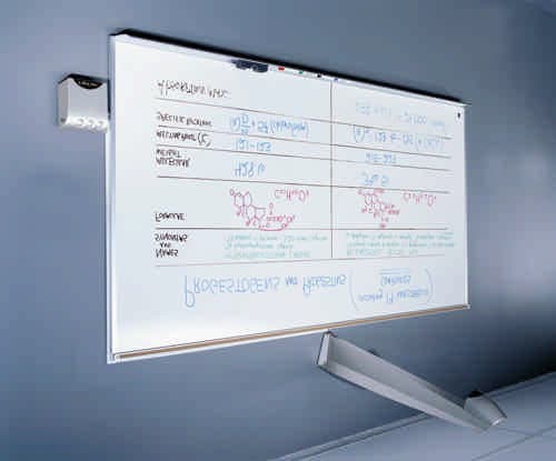
P6I-COPYCAM203
Oct 15, 2002COPYCAM
Equipment Class
DTS - Digital Transmission System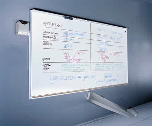
P6I-COPYCAM
Feb 24, 2002COPYCAM
Equipment Class
DSS - Part 15 Spread Spectrum Transmitter