P6XSBXW-166LHGE-4Wireless Broadband Router
SofaWare Technologies Ltd.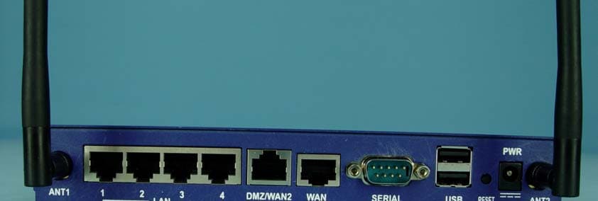
Click to zoom
Application Details
- Equipment Class
- DTS - Digital Transmission System
- Date of Grant
- Oct 05, 2004
- Application Purpose
- Original Equipment
- Date of Application
- Oct 05, 2004
- Equipment Note
- Wireless Broadband Router
- Frequency Range
- 2412.00000000 - 2462.00000000
- Company
- SofaWare Technologies Ltd.
- Country
- Israel
Documents & Files
Document Text
Text extracted from the exhibit documents filed with the FCC. Open a document above to read the original.
Users Manual
FCC DoC (1275x1650x16M jpeg)
Users Manual
Check Point Safe@Office Internet Security Appliance User Guide Version 4.6 Part No: 700797, June 2004 COPYRIGHT & TRADEMARKS Copyright © 2004 SofaWare, All Rights Reserved. No part of this document may be reproduced in any form or by any means without written permission from SofaWare. Information in this document is subject to change without notice and does not represent a commitment on part of SofaWare Technologies Ltd. SofaWare, Safe@Home and Safe@Office are trademarks, service marks, or registered trademarks of SofaWare Technologies Ltd. Check Point, the Check Point logo, FireWall-1, FireWall-1 SecureServer, FireWall-1 SmallOffice, FloodGate-1, INSPECT, IQ Engine, Meta IP, MultiGate, Open Security Extension, OPSEC, Provider-1, SecureKnowledge, SecureUpdate, SiteManager-1, SVN, UAM, User-to-Address Mapping, UserAuthority, Visual Policy Editor, VPN-1, VPN-1 Accelerator Card, VPN-1 Gateway, VPN-1 SecureClient, VPN-1 SecuRemote, VPN-1 SecureServer, and VPN-1 Edge are trademarks, service marks, or registered trademarks of Check Point Software Technologies Ltd. or its affiliates. All other product names mentioned herein are trademarks or registered trademarks of their respective owners. The products described in this document are protected by U.S. Patent No. 5,606,668 and 5,835,726 and may be protected by other U.S. Patents, foreign patents, or pending applications. SAFETY PRECAUTIONS Carefully read the Safety Instructions the Installation and Operating Procedures provided in this User's Guide before attempting to install or operate the appliance. Failure to follow these instructions may result in damage to equipment and/or personal injuries. Before cleaning the appliance, unplug the power cord. Use only a soft cloth dampened with water for cleaning. Any changes or modifications to this product not explicitly approved by the manufacturer could void any assurances of Safety or Performance and could result in violation of Part 15 of the FCC Rules. When installing the appliance, ensure that the vents are not blocked. Do not use the appliance outdoors. Do not expose the appliance to liquid or moisture. Do not expose the appliance to extreme high or low temperatures. Do not drop, throw, or bend the appliance since rough treatment could damage it. Do not use any accessories other than those approved by Check Point. Failure to do so may result in loss of performance, damage to the product, fire, electric shock or injury, and will void the warranty. Do not disassemble or open the appliance. Failure to comply will void the warranty. Do not route the cables in a walkway or in a location that will crimp the cables. POWER ADAPTER The appliance should only be used with the power adapter provided. The power adapter should be plugged into a surge protected power source. In addition, be careful not to overload the wall outlets, extension cords, etc. used to power this unit. Connect the power adapter only to power sources as marked on the product. To reduce risk of damage to the electric cord, remove it from the outlet by holding the power adapter rather than the cord. SECURITY DISCLAIMER The appliance provides your office network with the highest level of security. However, no product can provide you with absolute protection against a determined effort to break into your system. We recommend using additional security measures to secure highly valuable or sensitive information. Federal Communication Commission Interference Statement This equipment has been tested and found to comply with the limits for a Class B digital device, pursuant to Part 15 of the FCC Rules. These limits are designed to provide reasonable protection against harmful interference in a residential installation. This equipment generates, uses and can radiate radio frequency energy and, if not installed and used in accordance with the instructions, may cause harmful interference to radio communications. However, there is no guarantee that interference will not occur in a particular installation. If this equipment does cause harmful interference to radio or television reception, which can be determined by turning the equipment off and on, the user is encouraged to try to correct the interference by one of the following measures: - Reorient or relocate the receiving antenna. - Increase the separation between the equipment and receiver. - Connect the equipment into an outlet on a circuit different from that to which the receiver is connected. - Consult the dealer or an experienced radio/TV technician for help. This device complies with Part 15 of the FCC Rules. Operation is subject to the following two conditions: (1) This device may not cause harmful interference, and (2) this device must accept any interference received, including interference that may cause undesired operation. FCC Caution: Any changes or modifications not expressly approved by the party responsible for compliance could void the user's authority to operate this equipment. IMPORTANT NOTE: FCC Radiation Exposure Statement: This equipment complies with FCC radiation exposure limits set forth for an uncontrolled environment. This equipment should be installed and operated with minimum distance 20cm between the radiator & your body. This transmitter must not be co-located or operating in conjunction with any other antenna or transmitter. Contents Contents i Contents Chapter 1: Introduction...................................................................................1 About Your Check Point Safe@Office Appliance.........................................1 Safe@Office Products....................................................................................2 Safe@Office 105........................................................................................2 Safe@Office 110........................................................................................2 Safe@Office 225......................................................................…
Text truncated - open the document above for the full version.
Users Manual
Using Static Routes 140 Check Point Safe@Office User Guide c. Click Apply. The changes are saved. Deleting a Static Route Note: The “default” route cannot be deleted. To delete a static route 1. Click Network in the main menu, and click the Routes tab. The Static Routes page appears, with a listing of existing static routes. 2. In the desired route row, click the Delete icon. A confirmation message appears. 3. Click OK. The route is deleted. Viewing the Event Log Chapter 6: Viewing Reports 141 Chapter 6 This chapter describes the Safe@Office Portal reports. This chapter includes the following topics: . 144 . 147 Vi Viewing the Event Log.......................................................................141 Viewing Computers........................................................................... Viewing Connections........................................................................ Viewing Reports ewing the Event Log Yocan track network activity using the Event Log. The Event Log displays u e most recent events and color codes them. An event marked in this color... Indicates... th Table 20: Event Log Color Coding Bl ity update implemented by your Service Center ue Changes in your setup that you have made yourself or as a result of a secur Red Connection attempts that were blocked by your firewall. Orange Connection attempts that were blocked by your custom security rules Viewing the Event Log 142 Check Point Safe@Office User Guide An event marked in olor... Indicates... this c Green Traffic accepted by the firewall. ccept r, such tra y polic Service Center. By default, a Howeve by a securit ed traffic is not logged. ffic may be logged if specified y downloaded from your The logs detail the date and the time the evred, and its type. If the event is a communication attempt that was rejected by the firewall, the event incluon I, and the protocoltempt (for example, TCP or UDP). ent occur details de the source and destinati used for the communication at P address, the destination port NSafe@O logs tmation,ng o ote: You can configure the o a Syslog server. For infor ffice appliance to send event see Configuring Syslog Loggi n page 263. Viewing the Event Log Chapter 6: Viewing Reports 143 To view the event log • Click Reports in the main menu, and cb. The Event Log page appears. lick the Event Log ta You ca • Clic • Clicar all events. • If an event is highlighted in red, indicating a blocked attack on your network, you can display the attacker’s details, by clicking on the IP address of the attacking machine. The Safe@Office appliance queries the Internet WHOIS server, and a window displays the name of the entity to whom the IP address is registered and their contact information. This information is useful in tracking down hackers. n do any of the following: k the Refresh button to refresh the display. k the Clear button to cle Viewing Computers 144 Check Point Safe@Office User Guide V iewing Computers This option allows you to view the currently acti network. The active computers are graphically d ve computers on your isplayed, each with its name, IP e limit information. 1. Click Reports in the main menu, and click the Active Computers tab. The Active Computers page appears. address, and settings (DHCP, Static, etc.). You can also view nod To view the active computers If you configured High Availability, both the master and backup appliances are shown. If you are using Safe@Office 300W, the following is displayed next to wireless computers: • Transmission rate in Mbps Viewing Computers Chapter 6: Viewing Reports 145 mouse-over this icon to see the following statistics: Frames OK - The total number of frames that were successfully transmitted and received Errors - The total number of transmitted and received frames for which an error occurred Discarded/Dropped Frames - The total number of discarded or dropped frames transmitted and received Unicast Frames - The number of unicast frames transmitted and received Broadcast Frames - The number of broadcast frames transmitted an received • Signal strength in dB • An information icon - You can d Multicast Frames - The number of multicast frames transmitted and received If y com security ou are subscreDesk, a status message next to each puter indicahe computer complies with the SecureDesk level conditions. For information on SecureDesk, see Using SecureDesk on page 183. For an explanation of the status messages, see a e exceey your e, a warninde limit are markedmputers are still protected, but they are blocked from accessing the Internet through the Safe@Office appliance. ribed to Secu tes whether t SecureDesk Sttus Messages on page 191. If you ar licens ding the maximum number of computers allowed b g message appears, and the computers over the no in red. These co Note: Com counted fy the firewall. puters that did not communicate through the firewall are not or node limit purposes, even though they are protected b Viewing Computers 146 Check Point Safe@Office User Guide Note: To increase the number of computers allowed by your must upgrade your product. For further information, see Up license, you grading 2. h. imit window appears with installed software product and Your Software Product on page 258. To refresh the display, click Refres 3. To view node limit information, do the following: a. Click Node Limit. The Node L the number of nodes used. b. Click Close to close the window. Viewing Connections Chapter 6: Viewing Reports 147 ingtions View Connec This option allow ween your network and the extplayed as a list, specifying srrt, and the protocol used (TP To view the activ • Click Repns tab. The Active Connecti s you to view the currently active connections bet ernal world. The active connections are dis ou ce IP address, destination IP address and po C, UDP, etc.). e connections orts in the main menu, and click the Active Connectio ons page appears. You can do the following: • Click the Refresh button to refresh the display. • To view inf…
Text truncated - open the document above for the full version.
Cover Letter(s)
American Telecommunications Certification Body Inc. 6731 Whittier Ave, McLean, VA 22101 September 18, 2004 RE: SofaWare Technologies Ltd. FCC ID: P6XSBXW-166LHGE-4 After a review of the submitted information, I have a few comments on the above referenced Application. 1) The block diagram should show the frequencies of all oscillators in the TX device (CFR 2.1033(a)(5)), unless this portion of the device is an OEM part. Please provide either the block diagram for the TX portion, or alternatively provide a parts list that shows that this part is provided by another manufacturer. If necessary, please update the confidentiality letter to include the parts list. 2) The schematics do not include the RF mini-PCI card. Note that a schematic for the TX portion of the device is required as specified 2.1033(b)(5) for the RF section. Please provide either a schematic for the mini-PCI card or as an alternative, you may provide a parts list that lists that shows that this part is provided by another manufacturer. Please provide either a schematic or parts list as specified. If necessary, please update the confidentiality letter to include the parts list. 3) The Representative shown on a DoC must be for a U.S. based address. Please correct. 4) The FCC ID must include the “FCC ID:” on a single line. Currently this is shown on a line separate from the actual number. Please correct. Timothy R. Johnson Examining Engineer mailto: [email protected] The items indicated above must be submitted before processing can continue on the above referenced application. Failure to provide the requested information may result in application termination. Correspondence should be considered part of the permanent submission and may be viewed from the Internet after a Grant of Equipment Authorization is issued. Please do not respond to this correspondence using the email reply button. In order for your response to be processed expeditiously, you must submit your documents through the AmericanTCB.com website. Also, please note that partial responses increase processing time and should not be submitted. Any questions about the content of this correspondence should be directed to the sender.
Cover Letter(s)
Dear Tim The block, shem, coverletter DoC and label have been revised and uploaded to website today. Please check. Thanks for your assistance! Best Regards Wendy Liao Page 1 of 1In 10/6/2004Printed for "Timothy R. Johnson" <[email protected]>
External Photos
Page 1 CONSTRUCTION PHOTOS OF EUT Page 2 Page 3
ID Label/Location Info
FCC ID Label Location
ID Label/Location Info
EMI Label-SVPNW 0923-rev (856x1976x16M jpeg)
Internal Photos
Page 4 Page 5 Page 6 Page 7 Page 8 Page 9 Page 10
Operational Description
FCC ID: P6XSBXW-166LHGE-4 ADT No.930629L07 Operational Description This device is a Wireless Broadband Router which operates in the 2.4GHz frequency spectrum with throughput of up to 54Mbps which OFDM technique will be applied. If the signal to noise radio is too poor which could not support 54Mbps, the 11Mbps data rate with CCK technique will be applied. The transmitter of the EUT is powered by power adapter and connected with managing computer through RJ45 port. The antenna is Dipole antenna with SMA connector. Under normal use condition, the user has to keep at least 20cm separation distance between radiator and the body of the user. The other instruction, please have a look at the users manual.
RF Exposure Info
Report No: SA930629L07 1 RF EXPOSURE REPORT REPORT NO.: SA930629L07 MODEL NO.: SBXW-166LHGE-4 ACCORDING: FCC Guidelines for Human Exposure IEEE C95.1 APPLICANT: SofaWare Technologies Ltd. ADDRESS: 3 Hilazon St. Ramat-Gan Israel, 52522 ISSUED BY: Advance Data Technology Corporation LAB LOCATION: No. 19, Hwa Ya 2 nd Rd., Wen Hwa Tsuen, Kwei Shan Hsiang, Taoyuan Hsien 333, Taiwan Report No: SA930629L07 2 RF Exposure Measurement (Mobile Device) 1. Introduction In this document, we try to prove the safety of radiation harmfulness to the human body for our product. The limit for Maximum Permissible Exposure (MPE) specified in FCC 1.1310 is followed. The Gain of the antenna used in this product is measured in a Fully Anechoic Chamber (FAC) calibrated for antenna measurement in ADT, and also the maximum total power input to the antenna is measured. Through the Friis transmission formula and the maximum gain of the antenna, we can calculate the distance, away from the product, where the limit of MPE is reached. Although the Friis transmission formula is a far field assumption, the calculated result of that is an over-prediction for near field power density. We will take that as the worst case to specify the safety range. 2. RF Exposure Limit According to FCC 1.1310: The criteria listed in the following table shall be used to evaluate the environmental impact of human exposure to radio-frequency (RF) radiation as specified in 1.1307(b) LIMITS FOR MAXIMUM PERMISSIBLE EXPOSURE (MPE) Frequency Range (MHz) Electric Field Strength (V/m) Magnetic Field Strength (A/m) Power Density (mW/cm 2 ) Average Time (minutes) (A)Limits For Occupational / Control Exposures 300-1500......F/3006 1500-100,000......56 (B)Limits For General Population / Uncontrolled Exposure 300-1500......F/15006 1500-100,000......1.030 F = Frequency in MHz Report No: SA930629L07 3 3. Friis Formula Friis transmission formula : Pd = (Pout*G) / (4*pi*r 2 ) where Pd = power density in mW/cm 2 Pout = output power to antenna in mW G = gain of antenna in linear scale Pi = 3.1416 R = distance between observation point and center of the radiator in cm If we know the maximum Gain of the antenna and the total power input to the antenna, through the calculation, we will know the MPE value at distance r. Ref. : David K. Cheng, Field and Wave Electromagnetics, Second Edition, Page 640, Eq. (11-133). 4 EUT Operating condition The software provided by Manufacturer enabled the EUT to transmit and receive data at lowest, middle and highest channel individually. 5. Classification The antenna of the product, under normal use condition, is at least 20cm away from the body of the user. Warning statement to the user for keeping at least 20cm or more separation distance with the antenna should be included in users manual. So, this device is classified as Mobile Device. Report No: SA930629L07 4 6. Test Results 6.1 Antenna Gain The maximum Gain measured in Fully Anechoic Chamber is 2dBi or 1.58 (numeric). 6.2 Output Power Into Antenna & RF Exposure value at distance 20cm: For 802.11b: Channel Channel Frequency (MHz) Output Power to Antenna (mW) Power Density (mW/cm 2 ) Limit of Power Density (mW/cm 2 ) 1241256.2340.0181.0 6244289.1250.0281.0 11247270.7950.0221.0 For 802.11g: Channel Channel Frequency (MHz) Output Power to Antenna (mW) Power Density (mW/cm 2 ) Limit of Power Density (mW/cm 2 ) 1241231.6230.0101.0 6244279.4330.0251.0 11247244.6680.0141.0
Test Report
FCC ID: P6XSBXW-166LHGE-4 Report No.: RF930629L071Issued: July 29, 2004 FCC TEST REPORT REPORT NO.: RF930629L07 MODEL NO.: SBXW-166LHGE-4 RECEIVED: July 13, 2004 TESTED: July 21, 2004 ~ July 28, 2004 APPLICANT: SofaWare Technologies Ltd. ADDRESS: 3 Hilazon St., Ramat-Gan, Israel, 52522 ISSUED BY: Advance Data Technology Corporation LAB LOCATION: No. 19, Hwa Ya 2 nd Rd., Wen Hwa Tsuen, Kwei Shan Hsiang, Taoyuan Hsien 333, Taiwan This test report consists of 70 pages in total. It may be duplicated completely for legal use with the approval of the applicant. It should not be reproduced except in full, without the written approval of our laboratory. The client should not use it to claim product endorsement by CNLA or any government agencies. The test results in the report only apply to the tested sample. 0528 ILAC MRA FCC ID: P6XSBXW-166LHGE-4 Report No.: RF930629L072Issued: July 29, 2004 TABLE OF CONTENTS 1 CERTIFICATION ...........................................................................................................4 2 SUMMARY OF TEST RESULTS ...................................................................................5 2.1MEASUREMENT UNCERTAINTY................................................................................5 3 GENERAL INFORMATION............................................................................................6 3.1GENERAL DESCRIPTION OF EUT .............................................................................6 3.2DESCRIPTION OF TEST MODES ...............................................................................7 3.3GENERAL DESCRIPTION OF APPLIED STANDARDS ..............................................7 3.4DESCRIPTION OF SUPPORT UNITS .........................................................................8 3.5 CONFIGURATION OF SYSTEM UNDER TEST .........................................................9 4 TEST TYPES AND RESULTS .....................................................................................10 4.1CONDUCTED EMISSION MEASUREMENT .............................................................10 4.1.1 LIMITS OF CONDUCTED EMISSION MEASUREMENT...........................................10 4.1.2 TEST INSTRUMENTS................................................................................................10 4.1.3 TEST PROCEDURES ................................................................................................ 11 4.1.4 DEVIATION FROM TEST STANDARD....................................................................... 11 4.1.5 TEST SETUP..............................................................................................................12 4.1.6 EUT OPERATING CONDITIONS ...............................................................................12 4.1.7 TEST RESULTS .........................................................................................................13 4.2RADIATED EMISSION MEASUREMENT ..................................................................19 4.2.1 LIMITS OF RADIATED EMISSION MEASUREMENT................................................19 4.2.2 TEST INSTRUMENTS................................................................................................20 4.2.3 TEST PROCEDURES ................................................................................................21 4.2.4 DEVIATION FROM TEST STANDARD.......................................................................21 4.2.5 TEST SETUP..............................................................................................................22 4.2.6 EUT OPERATING CONDITIONS ...............................................................................22 4.2.7 TEST RESULTS .........................................................................................................23 4.2.8 TEST RESULTS (A)....................................................................................................25 4.2.9 TEST RESULTS (B)....................................................................................................28 4.36dB BANDWIDTH MEASUREMENT..........................................................................33 4.3.1 LIMITS OF 6dB BANDWIDTH MEASUREMENT .......................................................33 4.3.2 TEST INSTRUMENTS................................................................................................33 4.3.3 TEST PROCEDURE...................................................................................................34 4.3.4 DEVIATION FROM TEST STANDARD.......................................................................34 4.3.5 TEST SETUP..............................................................................................................34 4.3.6 EUT OPERATING CONDITIONS ...............................................................................34 4.3.7 TEST RESULTS (A)....................................................................................................35 4.3.8 TEST RESULTS (B)....................................................................................................39 4.4MAXIMUM PEAK OUTPUT POWER..........................................................................43 4.4.1 LIMITS OF MAXIMUM PEAK OUTPUT POWER MEASUREMENT ..........................43 4.4.2 TEST INSTRUMENTS................................................................................................43 4.4.3 TEST PROCEDURES ................................................................................................44 4.4.4 DEVIATION FROM TEST STANDARD.......................................................................44 4.4.5 TEST SETUP..............................................................................................................44 4.4.6 EUT OPERATING CONDITIONS ...............................................................................44 FCC ID: P6XSBXW-166LHGE-4 Report No.: RF930629L073Issued: July 29, 2004 4.4.7 TEST RESULTS…
Text truncated - open the document above for the full version.
Test Setup Photos
FCC ID: P6XSBXW-166LHGE-4 Report No.: RF930629L0768Issued: July 29, 2004 5 PHOTOGRAPHS OF THE TEST CONFIGURATION CONDUCTED EMISSION TEST FCC ID: P6XSBXW-166LHGE-4 Report No.: RF930629L0769Issued: July 29, 2004 RADIATED EMISSION TEST
Contact Information
Applicant
Liran Eshel(Director)
Technical Contact
Advance Data Technology CorporationEllis Wu
[email protected]+886-3-318-3232
No. 19 Hwa Ya 2nd rd. · Kueishan Taoyuan · Taiwan
Non-Technical Contact
Advance Data Technology CorporationEllis Wu
[email protected]+886-3-318-3232
Test Firm
Bureau Veritas CPS (H.K.) Ltd. Taoyuan BranchTommy Wu
Technical Specifications
| # | Rule Parts | Frequency Range | Power Output |
|---|---|---|---|
| 1 | 15C | 2.41 GHz - 2.46 GHz | 89.00 mW |
Other Applications from SofaWare Technologies Ltd.
P6XSBX-166LHGE-5
Nov 13, 2006Safe@Office/VPN-1 Edge
Equipment Class
JBP - Part 15 Class B Computing Device Peripheral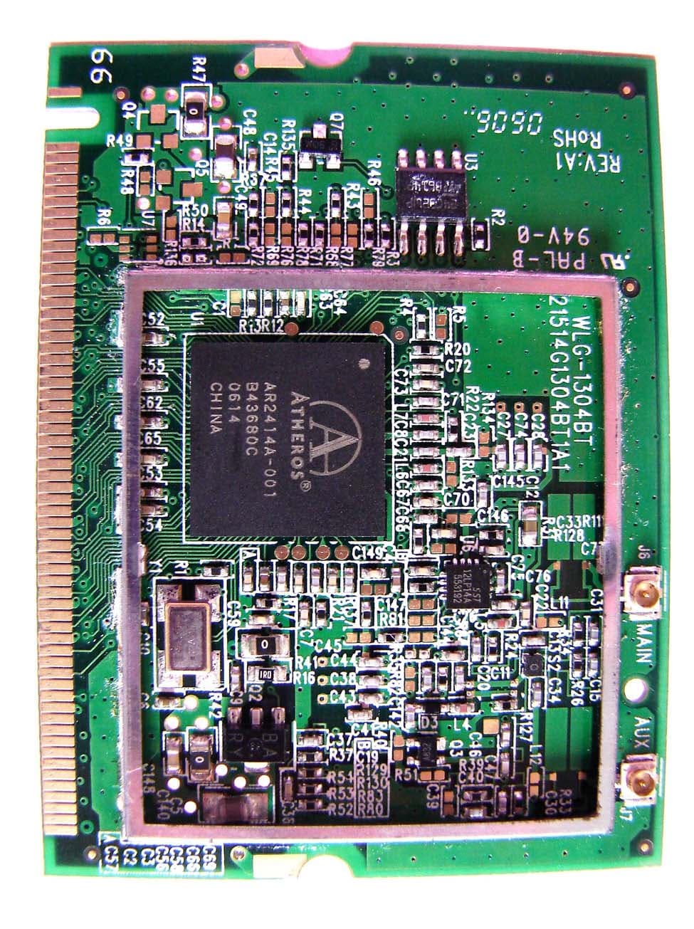
P6XSBX-11GWLAN-5
Oct 24, 20062.4G WLAN MINI PCI MODULAR
Equipment Class
DTS - Digital Transmission System
P6XSBXW-166LHGE-6
Aug 16, 2006Wireless Broadband Router
Equipment Class
DTS - Digital Transmission System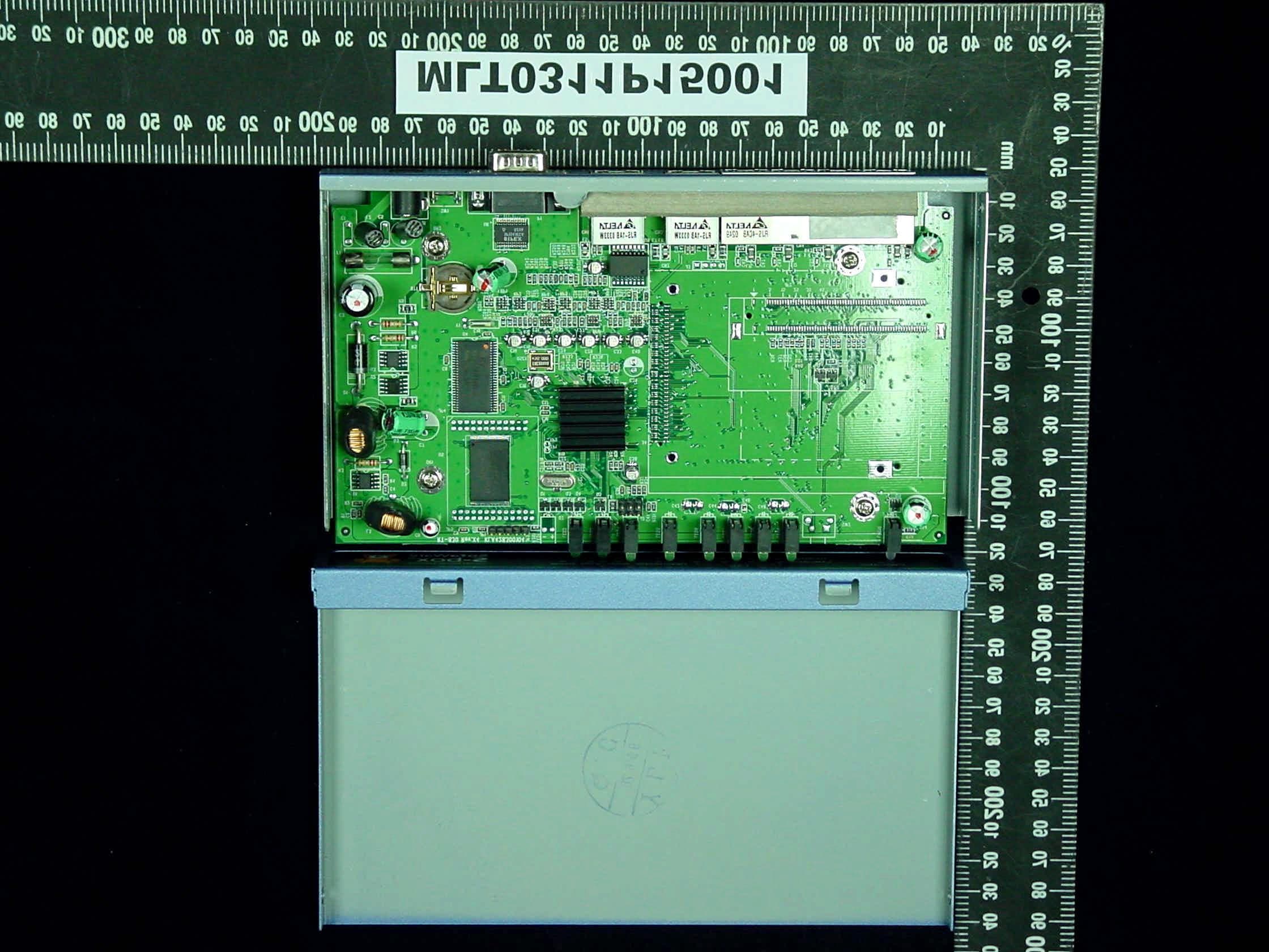
P6XSBX-166LHGE-2
Dec 11, 2003Internet Security Appliance
Equipment Class
JBP - Part 15 Class B Computing Device Peripheral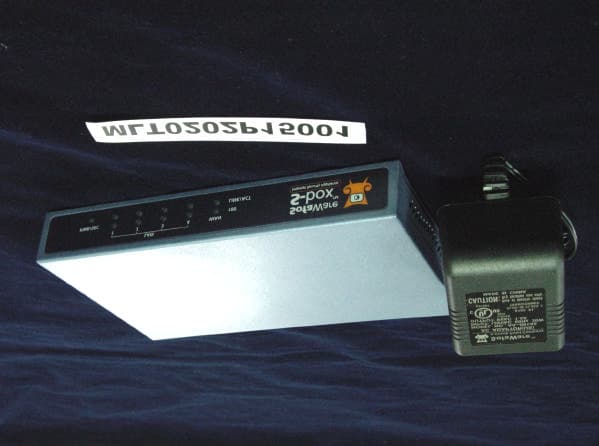
P6XSBX-133LHE-1
Feb 25, 2002Broadband Sharing Router
Equipment Class
JBP - Part 15 Class B Computing Device Peripheral