P7QRHV-1GSM 1900 PCS CELLULAR TELEPHONE
Vertu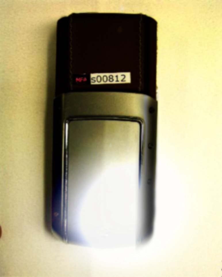
Click to zoom
Application Details
- Equipment Class
- PCE - PCS Licensed Transmitter held to ear
- Date of Grant
- Oct 05, 2003
- Application Purpose
- Original Equipment
- Date of Application
- Oct 05, 2003
- Equipment Note
- GSM 1900 PCS CELLULAR TELEPHONE
- Frequency Range
- 1850.20000000 - 1909.80000000
- Company
- Vertu
- Country
- United Kingdom
Documents & Files
Document Text
Text extracted from the exhibit documents filed with the FCC. Open a document above to read the original.
Users Manual
QUICK GUIDE quickguide.book Page i Thursday, August 21, 2003 3:43 PM quickguide.book Page ii Thursday, August 21, 2003 3:43 PM TABLE OF CONTENTS PAGE 2>WELCOME 2 >VERTU PACKAGING CONTENTS 3 >CONVENTIONS 4 >IMPORTANT INFORMATION 5 >SAFETY POINTS 8 >VERTU PHONE LAYOUT 10 >THE BATTERY AND SIM CARD 13 >VERTU PHONE KEYPAD 14 >SWITCHING ON YOUR VERTU PHONE 15 >SETTING THE TIME AND DATE 17 >DISPLAY ICONS AND INDICATORS 18 >MAKING CALLS 21 >EMERGENCY CALLS 22 >KEYPAD LOCK 24 >DIRECTORY 26 >TEXT MESSAGES 29 >VERTU CONCIERGE 30 >ACCESSORIES 39 >CD-ROM 41 >CARE AND MAINTENANCE 43 >BATTERY INFORMATION 44 >SAFETY INFORMATION 47 >SPECIFICATIONS 48 >GLOSSARY OF TERMS 49 >WARRANTY 54 >FDA UPDATE ON WIRELESS PHONES 61 >SAFE & RESPONSIBLE PHONE USE 64 >FCC NOTICE 66 >INDUSTRY CANADA NOTICE 67 >ACA NOTICE 68 >EU R&TTE NOTICE 69 >ICNIRP NOTICE 70 >GENERIC SAR NOTICE 71 >DECLARATION OF CONFORMITY quickguide.book Page 1 Thursday, August 21, 2003 3:43 PM Welcome 2 WELCOME It begins with a vision. A bold new design delivering superior craftsmanship and meticulous detail. Beautifully united with technology which evolves over time. And presented with a level of personal service that is without equal. It continues with a commitment to creativity, originality and excellence, drawing inspiration from human relationships, natural beauty and the arts. It explores the connections between people and celebrates the spirit of communication. And ultimately, it fulfills an uncompromising mission. To build an instrument of exceptional longevity, artistry and craftsmanship. The result is unparalleled communication - the experience is Vertu. VERTU PACKAGING CONTENTS 1Vertu phone 1Certificate of ownership 1Concierge booklet 1Microfibre polishing cloth 1Quick guide 1CD-ROM 1Battery 1Charger cable or connection lead 1Regional charger 1Headset 1Back cover release key quickguide.book Page 2 Thursday, August 21, 2003 3:43 PM Conventions 3 CONVENTIONS The following conventions are used in this Quick guide: menu Represents text that appears on your Vertu phone’s display, for example, “From the stand-by display, press menu.” SENDRepresents a Vertu phone key, for example, “Press the SEND key to make the call.” Caution. Important information relating to health and safety. Represents a tip. Useful information or a quick way to access or operate a feature. Represents a note. Points to be aware of when using your Vertu phone. User manual References are made throughout this guide to the User manual. You will find it on the CD-ROM supplied with your Vertu phone. If you do not have access to a compatible computer, contact Vertu Concierge, who can arrange for a printed copy to be despatched to you at your earliest convenience. quickguide.book Page 3 Thursday, August 21, 2003 3:43 PM Important Information 4 IMPORTANT INFORMATION The wireless phone described in this guide is approved for use on EGSM 900 and GSM 1900 networks. Contact your service provider for more information about networks. When using your Vertu phone, obey all laws and respect privacy and legitimate rights of others. NETWORK SERVICES To use the phone you must have service from a wireless service provider. Many of the features in your Vertu phone depend on features in the wireless network to function. These Network Services may not be available on all networks or you may have to make specific arrangements with your service provider before you can utilise Network Services. Your service provider may need to give you additional instructions for their use and explain what charges will apply. Some networks may have limitations that affect how you can use Network Services. For instance, some networks may not support all language-dependent characters and services. Your service provider may have also requested that certain features be disabled or not activated in your Vertu phone. If so, they will not appear on your menus. Contact your service provider for more information. SHARED MEMORY Some of the data features in your Vertu phone share memory. Using one or more of these features may reduce the memory available for the remaining features sharing memory. For example, saving many hundreds of phone book entries may use all of the available memory. Your phone may display a message that the memory is full when you try to use a shared memory feature. In this case, delete some of the information or entries stored in the shared memory features before continuing. Some of the features, such as the directory, have a certain amount of memory specially allotted to them in addition to the amount of memory shared with other features. Warning. All of your Vertu phone’s features, other than the alarm clock, require the phone to be switched on to use the features. Do not switch your Vertu phone on when wireless phone use may cause interference or danger. quickguide.book Page 4 Thursday, August 21, 2003 3:43 PM Safety points 5 SAFETY POINTS Your phone an internal antenna. As with any other radio transmitting device, do not touch the antenna unnecessarily when the phone is switched on. Contact with the antenna affects call quality and may cause the phone to operate at a higher power level than otherwise needed. Avoiding contact with the antenna during a call optimises the antenna performance and the talk time of your Vertu phone. Your Vertu phone and its accessories may contain small parts. Keep them out of reach of small children. For full safety instructions refer to “safety information” on page 44. Additional information is also available in the User manual on the CD-ROM. Caution. Do not switch on the phone when wireless phone use is prohibited or when it may cause interference or danger. Please read these simple guidelines. Disregarding these rules may be dangerous or illegal. quickguide.book Page 5 Thursday, August 21, 2003 3:43 PM Safety points 6 0 ROAD SAFETY COMES FIRST INTERFERENCE SWITCH OFF IN HOSPITALS SWITCH OFF IN AIRCRAFT SWITCH OFF WHEN REFUELLING SWITCH OFF NEAR BLASTING USE SENSIBLY QUA…
Text truncated - open the document above for the full version.
Cover Letter(s)
Applicant reply - 31002.txt From: M. Flom Associates, Inc. [[email protected]] Sent: Wednesday, October 01, 2003 7:16 PM To: [email protected] Subject: Vertu FCC ID: P7QRHV-1 Job 1330UC3 Bruno: Item 4) Maximum peak R.F. Power (Radiated) measured (page 10 of report) was 30.0 dbm EIRP plus 0.1 db for path loss for a total of 30.1 dbm, EIRP. Section 7.1 and 7.2 of the SAR Report shows a maximum of 30.1 dbm, EIRP or 1.02 watts, EIRP as shown on Form 731. We have added EIRP to item 14 of Form 731. Amended page is attached. Regards, Mort mf/cva M. Flom Associates, Inc. Confidential - The information in this message is only intended for the person(s) or organization(s) to whom it is addressed. If you are not that person, please contact the sender, and destroy this copy. Page 1
Cover Letter(s)
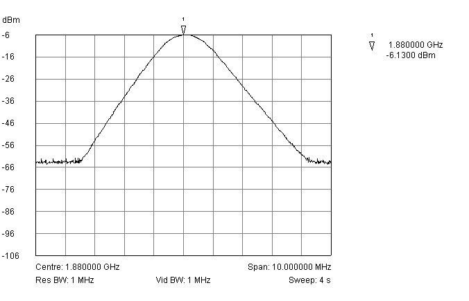
Correspondence Summary Questions and Answers 09/30/2003 SUBJECT: VERTU LTD. - FCC ID: P7QRHV-1 TCB questions: 1. Internal photos – Exhibit 3: Please, provide photos with the shielding cans removed. Alternatively, please, provide Gerber files showing PCB layout including silkscreen, components placement and reference designators, etc. 2. Part 2.1033(c)(8): The information required under this section were not provided in the test report, neither in the user’s manual. Please, submit such data. 3. Part 24.238 – Band-edges: Please, provide an additional plot with a RBW=VBW=1MHz to show how the reference level was set for compliance with the limit of –13dBm. The plots provided show a limit at –49dBm. Please, add an explanation in the test report. 4. The issue was for the Radiated power EIRP reported and not the conducted power: EMC test report lists 25dBmEIRP and SAR report approximately 30dBm EIRP. The conducted output power levels were Ok. Please, revise the EMC test report as to harmonize the power levels reported. Previous question: 4. SAR report section 7.1 and 7.2: The EIRP levels listed differ from the values reported in the Part 24E test report. Powers in SAR report must agree with EMC report. Please, revise accordingly. Applicant answers: 1) Attached please find photos with shield cans removed and Gerber files etc. As requested by the applicant, the silk screen and layout are to be considered confidential. 2) Collector voltage = 3.6 vdc Collector current = 0.278 amp 3) (a) Attached please find plot RBW = VBW = 1 MHz for setting of reference level. (b) R.F Power Output = 30 dbm EIRP, measured Losses = -31 db attenuator -3 db adapter -2 db cables/connectors Total -36 db Peak Reference level on Spectrum Analyzer = -6 dbm (30-36), therefore -13 dbm equals minus (30 + 13) = -43 db (EIRP) and -49 dbm represents -13 dbm. TIMCO ENGINEERING INC. 849 NW State Road 45 Newberry, Florida 32669 http://www.timcoengr.com 888.472.2424 F 352.472.2030 [email protected]
External Photos
COMPLIANCE DOCUMENTATION 1 (2) CONFIDENTIAL Photographs of P7QRHV-1 Mobile Phone AUGUST 2003 Exhibit 1: Front External View of Vertu FCCID: P7QRHV-1 COMPLIANCE DOCUMENTATION 2 (2) CONFIDENTIAL Photographs of P7QRHV-1 Mobile Phone AUGUST 2003 Exhibit 2: Back External View of Vertu FCCID: P7QRHV-1.
ID Label/Location Info
Kineta Instrument Label 03 Mar 03 Sheet 1 of 1 Preliminary Design Intent Layout Drawn by: B. Powell Dimensions in mm Scale 1:1 TYPE RHV-1MODEL ASCENTXXXXXXX CODE / FCC ID / IC / IMEI / DJPT : xxxxxxx P7QRHV-1 4299A-RHV1 xxxxxx/xx/xxxxxx xxxxx/POSTEL/2003 TYPE RHV-1MODEL KINET A XXXXXXX CODE / FCC ID / IC / IMEI / DJPT : xxxxxxx xxxxxx-x xxxxx-xxxx xxxxxx/xx/xxxxxx xxxxx/POSTEL/2003 s MADE IN U.K. TYPE RHV-1 MODEL KINET A XXXXXXX CODE / FCC ID / IC / IMEI / CMII / FACTORY CODE / xxxxxxx xxxxxx-x xxxxx-xxxx xxxxxx/xx/xxxxxx xxxxxxxxxx xxx Chinese CCC Label: Place label over ellipse as shown here by dotted line. Kineta Inside Instrument Label St andard Worldwide Kineta Inside Instrument Label Chinese Requirements and Sticker Placement Kineta Inside Instrument Label Sticker Placement for Taiwan, Malaysia & Singapore Product Code Fonts: Titles: Engravers' Gothic BT Regular 3.8 Point - 6.25 Leading - 200 Tracking Factory Code = 20 Tracking Title includes the first slash "/" Numbers: Berthold Akzidenz Grotesk BE Medium 3.8 Point - 6.25 Leading - 100 Tracking 16 Characters Max (incl. "slashes and dashes") Variable Width Type/Model Number Font: Engravers' Gothic BT Regular 3.8 Point - 5.4 Leading - 200 Tracking 14 characters Max - Variable Width Chinese Model Font: FZ Hei B01 Simplified 5.5 Point - 200 Tracking Type/Model Number Font: Engravers' Gothic BT Regular 3.8 Point - 4.4 Leading - 200 Tracking 14 characters Max - Variable Width Chinese Made in UK Font: FZ Hei B01 Simplified 5.5 Point - 200 Tracking
Internal Photos
COMPLIANCE DOCUMENTATION 1 (4) CONFIDENTIAL Photographs of P7QRHV-1 Mobile Phone AUGUST 2003 Exhibit 1: INTERNAL View of Vertu FCCID: P7QRHV-1 , battery cover removed to show location of TYPE DESIGNATION LABEL, and SIM card holder . COMPLIANCE DOCUMENTATION 2 (4) CONFIDENTIAL Photographs of P7QRHV-1 Mobile Phone AUGUST 2003 Exhibit 2:INTERNAL VIEW of Vertu FCCID:P7QRHV-1 Showing Circuitry. Bottom View of Printed wire Board, with removable shielding cans removed to show baseband ciruitry. COMPLIANCE DOCUMENTATION 3 (4) CONFIDENTIAL Photographs of P7QRHV-1 Mobile Phone AUGUST 2003 Exhibit 3: INTERNAL VIEW of Vertu FCCID: P7QRHV-1 . Top View of Printed Wire Board showing RF circuitry,adjacent to accociated RF Antenna assembly with printed element . Note:screening cans (beyond those removed) are placed and soldered as a part of the same process that solders RF components to the pwb and are fixed and not removable ! COMPLIANCE DOCUMENTATION 4 (4) CONFIDENTIAL Photographs of P7QRHV-1 Mobile Phone AUGUST 2003 Exhibit 4: INTERNAL VIEW of Vertu FCCID: P7QRHV-1 showing reverse of display module and interconnections.
Operational Description
VERTU CONFIDENTIAL 18th September 2003 DESCRIPTION OF CIRCUITRY SUPPRESSING SPURIOUS AND HARMONIC EMISSIONS PRODUCT FCC ID: P7QRHV-1 Circuits for suppression of spurious radiation All functional RF blocks are mounted on a single multilayer printed wire board (PWB). This board also contains the Master Controller Unit (MCU) and Digital Signal Processing (DSP) functions. All components are SMD type and mounted using reflow soldering. To ensure reliability, many of the shields are permenantly soldered during the component soldering process. The Printed Wire Board contains two common ground planes and common supply voltage plane. All other layers are signal layers with the unused areas acting as a ground plane. Layout design has been completed according to EMC/EMI guidelines. Shielding consists of: - Metal shields fitted to both sides of the circuit board, and enclose all major radiating components. This includes the PA and surrounding upperband components, but excludes the display. - Much of the phone casing is laminated onto stainless steel or other metals, which act as additional secondary shielding. Additional Filtering measures: - Engine I/P and O/P lines are fitted with additional filtering components where appropriate. - System connector to accessories is filtered by using passive components Power Limiting The desired transmitted power is adjusted by a power control loop. The loop contains RF detector, loop filters, diode rectifier and an error amplifier. Active components for the power control are N102, V105 and N100. FCC ID: P7QRHV-1 Applicant:Vertu Ltd. Copyright © 2003 Vertu Ltd.
Operational Description
VERTU CONFIDENTIAL 18thSept 2003 Theory of operation Vocabulary MS = Mobile Station E-GSM = Enhanced Global System for Mobile communications GSM = Global System for Mobile communications HW = Hardware (drivers) RAM = Random-Access Memory ROM = Read-Only Memory SPEC = Specification SW = Software PWB = Printed Wire Board RF = Radio Frequency BB = BaseBand Technical Summary The P7QRHV-1 is a dual-band radio transceiver unit for the E-GSM900 and GSM1900 networks. In E-GSM900 band MS is operating as power class IV providing 15 power levels with highest power level 5. GSM1900 is power class 1 unit providing 16 power levels with highest power level 0. In the USA, following convention used by all GSM mobile Phones, only the GSM1900 mode Transmission will be active and the GSM900 mode is disabled. The transceiver is a true 3 Volt transceiver. The transceiver has Full rate (FR) and Enchanced Full Rate (EFR) and Half rate speech (HR) codecs. Half rate is only available in GSM900 Mode. The transceiver has one PWB structure, which uses ground planes inside PWB as shielding between different modules. A printed flexy circuit provides the main electrical connection between the PWB and peripherals. The transceiver has full graphic display and microswitch key based user interface. FCC ID: P7QRHV-1 Applicant: Vertu Ltd. Copyright © 2003 Vertu Ltd VERTU CONFIDENTIAL 18thSept 2003 FCC ID: P7QRHV-1 Tranceiver combines an integral printed antenna, housed in the top of the casing, see photo exhibits, RF circuitry. There is no external antenna connection. The transceiver has an equalised earliece and OMNI type microphone. Applicant: Vertu Ltd. Copyright © 2003 Vertu Ltd VERTU CONFIDENTIAL 18thSept 2003 FCC ID: P7QRHV-1 Circuit Description The ZE4 engine module, as used in the P7QRHV-1 consists one main PWB with BB/RF sub modules housed within shielding cans fitted to both sides of the board. Ground planes inside the PWB are used as shielding between RF/BB and UI sections. The Different modules are interconnected with a printed flexy circuit. The phone can be connected to accessories via system connector in the base of the phone. This provides the connection for the charger, headset , datacable and optional desk stand. The RF submodule receives and demodulates radio frequency signals from the base station and transmits modulated RF signals to the base station. It consists of functional submodules Receiver, Frequency Synthesizer and Transmitter. The Baseband submodule contains audio,control, signal processing and power supply functions. Applicant: Vertu Ltd. Copyright © 2003 Vertu Ltd VERTU CONFIDENTIAL 18thSept 2003 FCC ID: P7QRHV-1 Interconnection Diagram Figure 1. Interconnection Baseband System/RF ENGINE BOARD MODULE Display Battery Headset Charger Antenna Earpiece Vibra Mic User Interface Hands Free Speaker Integral interconnects are routed via a printed flexy circuit Applicant: Vertu Ltd. Copyright © 2003 Vertu Ltd VERTU CONFIDENTIAL 18thSept 2003 Basic Specifications Table 1. Basic Specifications (E-GSM) Parameter E-GSM900 Cellular system E-GSM 900 TX frequency band 880,2 ... 914,8 MHz RX frequency band 925,2 ... 959,8 MHz Duplex spacing 45 MHz Number of RF channels 174 Channel spacing 200 kHz Power class 4 Power levels 15 Method of frequency synthesis Digital phase locked loop UHF 3520 ... 3980 MHz Frequency control 26 MHz VCTCXO: AFC used Receiver type Direct conversion Modulator type GMSK Table 2. Basic Specifications (PCS band) Parameter GSM1900 Cellular system GSM 1900 TX frequency band 1850,2 ... 1909,8 MHz RX frequency band 1930,2 ... 1989,8 MHz Duplex spacing 80 MHz Number of RF channels 299 Channel spacing 200 kHz Power class 1 Power levels 16 Method of frequency synthesis Digital phase locked loop UHF 3520 ... 3980 MHz Frequency control 26 MHz VCTCXO: AFC used Receiver type Direct conversion Modulator type GMSK FCC ID: P7QRHV-1 Applicant: Vertu Ltd. Copyright © 2003 Vertu Ltd VERTU CONFIDENTIAL 18thSept 2003 Functional Block Diagram Diplay Light Keypad SIM Display MA CCON T/ COB RX Ha DS P Dec oder TX Cod er DA C AD C DA C LN PA T X / R X S w MCU MCU A SQ UID Earpiece AD C Fla sh 1 2 3 4 5 6 1 2 3 4 5 6 Yam aha Ene rgy Mg mt Po wer Batt HFS Mic FCC ID: P7QRHV-1 Applicant: Vertu Ltd. Copyright © 2003 Vertu Ltd VERTU CONFIDENTIAL 18thSept 2003 Technical Specifications Modes of Operation P7QRHV-1 operates in normal,cellular mode and a local mode for service: - Normal mode, the phone is controlled by Cellular System SW and partly by basestation - Local mode, used by Production and After Sales. Normal Mode In Normal mode, the phone performs all the tasks to place and release calls. Also charging and communication between accessories and phone are done during this mode by Operating System SW. Signaling and handover functions are supported by basestation. Power off In the power-off mode only CCONT is active. Power-off mode can be left by pushing the -key, connecting charger to the phone, real time clock interrupt. Idle / standby The phone is in SERV-state listening to the network and waiting for the page. Call The phone call is going on and during most of the time all RF- and BB-parts are on. Separate parts are turned off when they are not needed in order to save power. Local Mode Local mode is used for testing purposes by Product Development, Production and After Sales. The Cellular Software is stopped (no signalling to base station), and the phone is controlled by MBUS/FBUS messages by the controlling PC. FCC ID: P7QRHV-1 Applicant: Vertu Ltd. Copyright © 2003 Vertu Ltd
RF Exposure Info
TCC Oulu Exhibit 11: SAR Report DTX08008-EN Applicant: Nokia Corporation FCC ID: P7QRHV-1 Copyright 2003 Nokia Corporation 1 (13) SAR Compliance Test Report Test report no.: Not numbered Date of report: 2003-08-29 Number of pages: 50 Contact person: Pentti Pärnänen Responsible test engineer: Pentti Pärnänen Testing laboratory: Nokia Corporation Yrttipellontie 6 P.O. Box 300 FIN-90401 OULU Finland Tel. +358-7180-08000 Fax. +358-7180-47222 Client: Vertu Ltd Beacon Hill Road Church Crookham Hampshire GU52 8DY United Kingdom Tel. +44-1252-61100 Fax. +44-1252-61300 Tested devices: P7QRHV-1 (Detailed information for each device is listed in section 1). Supplement reports: Testing has been carried out in accordance with: 47CFR §2.1093 Radiofrequency Radiation Exposure Evaluation: Portable Devices IEEE P1528-200X Draft 6.4 Recommended Practice for Determining the Peak Spatial-Average Specific Absorption Rate (SAR) in the Human Body Due to Wireless Communications Devices: Experimental Techniques FCC OET Bulletin 65 (Edition 97-01), Supplement C (Edition 01-01) Evaluating Compliance with FCC Guidelines for Human Exposure to Radiofrequency Electromagnetic Fields Documentation: The documentation of the testing performed on the tested devices is archived for 15 years at TCC Oulu Test results: The tested device complies with the requirements in respect of all parameters subject to the test. The test results and statements relate only to the items tested. The test report shall not be reproduced except in full, without written approval of the laboratory. Date and signatures: 2003-08-29 For the contents: Pentti Pärnänen Manager, TCC Oulu Kai Niskala Test Engineer TCC Oulu Exhibit 11: SAR Report DTX08008-EN Applicant: Nokia Corporation FCC ID: P7QRHV-1 Copyright 2003 Nokia Corporation 2 (13) CONTENTS 1. SUMMARY FOR SAR TEST REPORT............................................................................................................................ 3 1.1 MAXIMUM RESULTS FOUND DURING SAR EVALUATION.............................................................................................................3 1.1.1 Head Configuration .......................................................................................................................................................3 1.1.2 Body Worn Configuration...........................................................................................................................................3 1.1.3 Measurement Uncertainty..........................................................................................................................................3 2. DESCRIPTION OF TESTED DEVICE.............................................................................................................................. 4 2.1 PICTURE OF PHONE......................................................................................................................................................................4 2.2 DESCRIPTION OF THE ANTENNA..................................................................................................................................................4 2.3 BATTERY OPTIONS.......................................................................................................................................................................4 2.4 BODY WORN ACCESSORIES..........................................................................................................................................................5 3. TEST CONDITIONS.......................................................................................................................................................... 5 3.1 AMBIENT CONDITIONS.................................................................................................................................................................5 3.2 RF CHARACTERISTICS OF THE TEST SITE.......................................................................................................................................5 3.3 TEST SIGNAL, FREQUENCIES, AND OUTPUT POWER ...................................................................................................................5 4. DESCRIPTION OF THE TEST EQUIPMENT................................................................................................................. 6 4.1 SYSTEM ACCURACY VERIFICATION................................................................................................................................................6 4.2 TISSUE SIMULANTS......................................................................................................................................................................7 4.2.1 Head Tissue Simulant...................................................................................................................................................7 4.2.2 Muscle Tissue Simulant ................................................................................................................................................7 4.3 PHANTOMS...................................................................................................................................................................................8 4.4 ISOTROPIC E-FIELD PROBE ET3DV6..........................................................................................................................................8 5. DESCRIPTION OF THE TEST PROCEDURE................................................................................................................. 9 5.1 TEST POSITIONS..........................................................................................................................................................................9 5.1.1 Against Phantom Head................................................................................................................................................9 5.1.2 …
Text truncated - open the document above for the full version.
Test Report
FCC ID: P7QRHV-1 Transmitter Certification of FCC ID: P7QRHV-1 Model: Type RHV-1 to Federal Communications Commission Rule Part(s) 24E, Confidentiality Date Of Report: August 21, 2003 On the Behalf of the Applicant: Vertu Ltd. At the Request of: P.O. E68-1002896/06/25/2003 Vertu Ltd. Beacon Hill Road Church Crookham, Hampshire GU52 8DY UK Attention of: Mark Pope, Certification and Compliance Manager +44 1252 611135; FAX: -611302 Mobile: +44 7774 8158594 [email protected] Supervised By: Morton Flom, P. Eng. MFA p0370007, d0380042 FCC ID: P7QRHV-1 The applicant has been cautioned as to the following: 15.21 Information to User. The users manual or instruction manual for an intentional radiator shall caution the user that changes or modifications not expressly approved by the party responsible for compliance could void the user's authority to operate the equipment. 15.27(a) Special Accessories. Equipment marketed to a consumer must be capable of complying with the necessary regulations in the configuration in which the equipment is marketed. Where special accessories, such as shielded cables and/or special connectors are required to enable an unintentional or intentional radiator to comply with the emission limits in this part, the equipment must be marketed with, i.e. shipped and sold with, those special accessories. However, in lieu of shipping or packaging the special accessories with the unintentional or intentional radiator, the responsible party may employ other methods of ensuring that the special accessories are provided to the consumer, without additional charge. Information detailing any alternative method used to supply the special accessories for a grant of equipment authorization or retained in the verification records, as appropriate. The party responsible for the equipment, as detailed in § 2.909 of this chapter, shall ensure that these special accessories are provided with the equipment. The instruction manual for such devices shall include appropriate instructions on the first page of text concerned with the installation of the device that these special accessories must be used with the device. It is the responsibility of the user to use the needed special accessories supplied with the equipment. MFA p0370007, d0380042 FCC ID: P7QRHV-1 Table of Contents Rule Description Page . Test Report 1 2.1033(c) General Information Required 2 2.1033(c)(14) Rule Summary 5 . Standard Test Conditions and Engineering Practices 6 2.1046(a) Carrier Output Power (Conducted) 7 2.1046(a) ERP Carrier Power (Radiated) 9 2.1051, 2.1049(c), 24, 24.238(b). . Transmitter Conducted Measurements 11 2.1053(a) Field Strength of Spurious Radiation 16 2.1055(a)(1), 24.235 . . Frequency Stability (Temperature Variation) 20 2.1055(b)(1) Frequency Stability (Voltage Variation) 23 2.202(g) Necessary Bandwidth and Emission Bandwidth 24 MFA p0370007, d0380042 FCC ID: P7QRHV-1 Page Number 1 of 24. Required information per ISO/IEC Guide 25-1990, paragraph 13.2: a) Test Report b) Laboratory: (FCC: 31040/SIT) (Canada: IC 2044) M. Flom Associates, Inc. 3356 N. San Marcos Place, Suite 107 Chandler, AZ 85225 c) Report Number: d0380042 d) Client: Vertu Ltd. Beacon Hill Road Church Crookham, Hampshire GU52 8DY UK e) Identification: Type RHV-1 FCC ID: P7QRHV-1 Serial Numbers: 179460/2 and 179454/5 Description: GSM1900 PCS f) EUT Condition: Not required unless specified in individual tests. g) Report Date: August 21, 2003 EUT Received: July 28, 2003 h, j, k): As indicated in individual tests. i) Sampling method: No sampling procedure used. l) Uncertainty: In accordance with MFA internal quality manual. m) Supervised by: Morton Flom, P. Eng. n) Results: The results presented in this report relate only to the item tested. o) Reproduction: This report must not be reproduced, except in full, without written permission from this laboratory. Product Introduction The P7QRHV-1 Mobile phone combines PCS technology and performance with design and craftsmanship to produce a product available in a number of cosmetic finishes. As this is restricted to cosmetics all will have the same Model, Type and FCCID. The Electrical design is particularly robust and incorporates a self-contained, multiplayer, double-sided screened board with screening of the digital, base band and RF circuitry. Cosmetic finishing of the phone allows some variation of the Ceramic and Leather components, as well as levels of polishing and finishing and Colour, using these materials. The 2 cosmetic Finishes tested here i.e. Plain Black Finish and Silver coloured Finish, are selected as the most dis- similar versions of the product. Test results demonstrate the equivalence of products tested and the independence of these finishing components from electrical performance in any mix/match combination MFA p0370007, d0380042 FCC ID: P7QRHV-1 Page Number 2 of 24. List of General Information Required for Certification In Accordance with FCC Rules and Regulations, Volume II, Part 2 and to 24E, Confidentiality Sub-Part 2.1033 (c)(1): Name and Address of Applicant: Vertu Ltd. Beacon Hill Road Church Crookham, Hamp…
Text truncated - open the document above for the full version.
Contact Information
Applicant
Mark Pope(Certification and Compliance Manager)
Test Firm
M. Flom Associates, Inc.Morton Flom
Technical Specifications
| # | Rule Parts | Frequency Range | Power Output | Emission | Tolerance |
|---|---|---|---|---|---|
| 1 | 24E | 1.85 GHz - 1.91 GHz | 1.02 W | 256KGXW | 1.0000000000 ppm |
Other Applications from Vertu

P7QVM-03
Sep 13, 2015Cellular Telephone
Equipment Class
NII - Unlicensed National Information Infrastructure TX
P7QVM-01T
Jan 15, 2015Cellular Telephone
Equipment Class
DXX - Part 15 Low Power Communication Device Transmitter
P7QVM-01
Aug 12, 2014CELLULAR TELEPHONE
Equipment Class
PCE - PCS Licensed Transmitter held to ear
P7QRM-980V
May 29, 2014Cellular Telephone
Equipment Class
PCE - PCS Licensed Transmitter held to ear
P7Q-SP1V
Apr 29, 2014BLUETOOTH TRAVEL SPEAKER
Equipment Class
DSS - Part 15 Spread Spectrum Transmitter