P9OHORNET-TXTransmitter keyfob for Hornet systems
RF Solutions Ltd.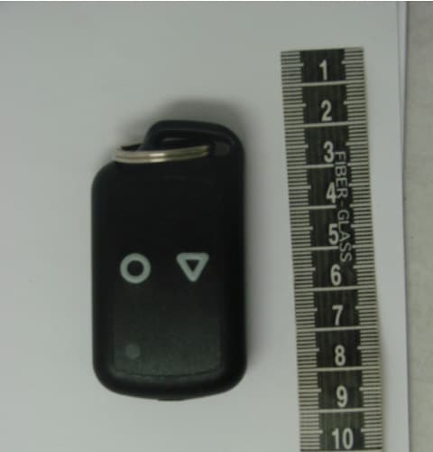
Click to zoom
Application Details
- Equipment Class
- DXX - Part 15 Low Power Communication Device Transmitter
- Date of Grant
- Jul 31, 2011
- Application Purpose
- Original Equipment
- Date of Application
- Jul 31, 2011
- Equipment Note
- Transmitter keyfob for Hornet systems
- Frequency Range
- 432.90000000 - 434.10000000
- Company
- RF Solutions Ltd.
- Country
- United Kingdom
Documents & Files
Document Text
Text extracted from the exhibit documents filed with the FCC. Open a document above to read the original.
Users Manual
HORNET Remote Control Systems HORNET Remote Control SystemsHORNET Remote Control Systems HORNET Remote Control Systems DS HORNET-10 Description DescriptionDescription Description Supplied complete ready to go the HORNET is a rugged IP68 weatherproof remote control system. Built in mounting points and easy wiring using High Quality screw Terminals. With a range of up to100m the HORNET is ideal for a wide variety of switching appli- cations. Additional transmitters may be added using the ‘learn’ process, any button on the transmitter can be used to control one or many outputs of the receiver. • Up to 100metres Range • 1 – 3 Button versions • 12-30Vdc 0r 230Vac versions • Reliable FM Technology • Up to four 1000W Relay switches • Waterproof Receiver (IP68) • Momentary or Latching Relays • Any Switch Map to Any Relay Output • General Purpose Remote General Purpose Remote General Purpose Remote General Purpose Remote Switching SwitchingSwitching Switching • Electric Gates Electric GatesElectric Gates Electric Gates • Roller Shutter Doors Roller Shutter DoorsRoller Shutter Doors Roller Shutter Doors • Garden Lighting Garden LightingGarden Lighting Garden Lighting HORNET HORNETHORNET HORNET- -- -S1 / HORNET S1 / HORNETS1 / HORNET S1 / HORNET- -- -S2 / HORNET S2 / HORNETS2 / HORNET S2 / HORNET- -- -S3 (12 S3 (12S3 (12 S3 (12- -- -32Vdc Receivers) 32Vdc Receivers)32Vdc Receivers) 32Vdc Receivers) The HORNET system provides up to 4 isolated switches each capable of switching up to 6A @230V 1. Open the enclosure by removing the two fixing screws from the base of the enclosure and remove the antenna, the board should then slide out. 2. Wire the power as shown on Fig 1.1 3. Wire your chosen switch as required 4. Once the receiver is set-up; transmitter button 1 will switch relay 1 (button two to relay two and so on). Each button press will change the state of the relay (i.e. one press for on, one press for off). Advanced Operation Advanced OperationAdvanced Operation Advanced Operation To pair a new transmitter switch follow this procedure To pair a new transmitter switch follow this procedureTo pair a new transmitter switch follow this procedure To pair a new transmitter switch follow this procedure Any transmitter button can be configured to operate any of the receiver relays. Pair any Transmitter switch with a receiver relay by following this procedure: 1. Select the receiver output relay to learn to: 2. Briefly press the receiver Pairing switch (S2) once 3. The Learn LED will flash once to indicate relay 1 is selected 4. After the LED stops flashing, press the Learn switch again to select the next relay channel 5. Repeat step 4 until the required relay is selected. 6. Press the button on the transmitter you want to learn to the relay. 7. The Learn LED will flash to indicate Pairing is complete. Pairing a Transmitter to a Receiver Pairing a Transmitter to a ReceiverPairing a Transmitter to a Receiver Pairing a Transmitter to a Receiver The only limitation is that each receiver has a maximum memory for up to 40 pairings, these can be from the same or any number of transmitters. Erasing Receivers Memory Erasing Receivers Memory Erasing Receivers Memory Erasing Receivers Memory 1. Press and hold the receiver Learn Switch for approx 10 seconds. 2. When the Learn LED turns ON all memory is erased NOTE: NOTE:NOTE: NOTE: You cannot erase individual Tx encoders Configuring Relays Configuring Relays Configuring Relays Configuring Relays The jumper links set the outputs to be Momentary (operates as long as transmitter is operated) or Latching (Relay changes state each time transmitter is pressed). The jumper links are made / removed by the small link ‘cap’ placed over the pin header. See Fig 1.1 for location of jumper pins. Link Positions Link PositionsLink Positions Link Positions Relays RelaysRelays Relays LK1 LK1LK1 LK1 LK2 LK2LK2 LK2 RLY 1 RLY 1RLY 1 RLY 1 RLY 2 RLY 2RLY 2 RLY 2 RLY 3 RLY 3RLY 3 RLY 3 RLY 4 RLY 4RLY 4 RLY 4 Closed Closed Mom Mom Mom Mom Closed Open Mom Mom Latch Latch Open Closed Mom Latch Latch Latch Open Open Latch Latch Latch Latch HORNET HORNETHORNET HORNET- -- -S1M / HORNET S2M (230Vac Powered Receivers) S1M / HORNET S2M (230Vac Powered Receivers)S1M / HORNET S2M (230Vac Powered Receivers) S1M / HORNET S2M (230Vac Powered Receivers) The HORNET system provides up to 4 isolated switches each capable of switching up to 6A @230V 1. Open the enclosure by removing the two fixing screws from the base of the enclosure and the antenna, the board should then slide out. 2. Wire the power as shown on Fig 1.2 3. Wire your chosen switch as required 4. Once the receiver is set-up transmitter button 1 will switch relay 1 (button two relay two and so on). Each button will change the state of the relay (i.e. one press for on, one press for off). Advanced Operation Advanced OperationAdvanced Operation Advanced Operation Please Note: Please Note:Please Note: Please Note: During Learn and Erase the relays operate at high speed. They should be isolated from sensi- tive equipment during this process. To Pair additional Transmitter buttons to receiver Relay #1 To Pair additional Transmitter buttons to receiver Relay #1To Pair additional Transmitter buttons to receiver Relay #1 To Pair additional Transmitter buttons to receiver Relay #1 1. Apply power the receiver and wait 10secs for the unit to enter ‘normal operation’ mode. 2. Switch the receiver unit OFF and then ON again in ~1sec intervals FOUR FOURFOUR FOUR times finally leaving the unit powered. 3. The receiver emits a continuous ‘Click’ to confirm it is now in ‘learn’ Mode 4. Press the chosen transmitter button. 5. The receiver will acknowledge by sounding the a single ’buzz’ 6. Learn Process complete. To Pair additional Transmitter buttons to receiver Relay #2 To Pair additional Transmitter buttons to receiver Relay #2To Pair additional Transmitter buttons to receiver Relay #2 To Pair additional Transmitter buttons to receiver Relay #2 1. Apply pow…
Text truncated - open the document above for the full version.
Operational Description
11-06-21 RF SOLUTIONS Hornet operational description US000470: HORNET-TX The HORNET Key fob is a battery powered, manually activated, momentary push switch transmitter. When a push switch on the HORNET is pressed by a user, an input pin to the on-board MCU is pulled low and a wake up is sent to the MCU. When the MCU awakes and detects a switch activation it sends a transmission to an on- board Antenna. This transmission is a in the form of a pre-defined data packet of length 68ms, it is sent to the antenna via a band pass filter. The frequency of the transmission sent out from the antenna is 433.92MHz this is controlled using an 18.08MHz crystal connected to the MCU, accuracy of the frequency transmitted is ensured using the band pass filter.
Test Report
Document 75913457 Report 01 Issue 1 July 2011 Report On FCC Testing of the RF Solutions Ltd Hornet COMMERCIAL-IN-CONFIDENCE FCC ID: P90 HORNET TÜV SÜD Product Service Ltd, Octagon House, Concorde Way, Segensworth North, Fareham, Hampshire, United Kingdom, PO15 5RL Tel: +44 (0) 1489 558100. Website: www.tuvps.co.uk COMMERCIAL-IN-CONFIDENCE Document 75913457 Report 01 Issue 1 Page 1 of 19 COMMERCIAL-IN-CONFIDENCE REPORT ON FCC Testing of the RF Solutions Ltd Hornet Document 75913457 Report 01 Issue 1 July 2011 PREPARED FOR RF Solutions Ltd Unit 21 Cliffe Industrial Estate South Street Lewes East Sussex BN8 6JL PREPARED BY N Bennett Senior Administrator APPROVED BY M Jenkins Authorised Signatory DATED 21 July 2011 ENGINEERING STATEMENT The measurements shown in this report were made in accordance with the procedures described on test pages. All reported testing was carried out on a sample equipment to demonstrate limited compliance with FCC CFR 47 Part 15C. The sample tested was found to comply with the requirements defined in the applied rules. Test Engineer(s); G Lawler COMMERCIAL-IN-CONFIDENCE Document 75913457 Report 01 Issue 1 Page 2 of 19 COMMERCIAL-IN-CONFIDENCE CONTENTS Section Page No 1 REPORT SUMMARY ................................................................................................................... 3 1.1 Introduction ................................................................................................................................... 4 1.2 Brief Summary of Results ............................................................................................................. 5 1.3 Declaration of Build Status ........................................................................................................... 6 1.4 Product Information ...................................................................................................................... 7 1.5 Test Conditions ............................................................................................................................. 8 1.6 Deviations From the Standard ...................................................................................................... 8 1.7 Modification Record ...................................................................................................................... 8 2 TEST DETAILS ............................................................................................................................ 9 2.1 Field Strength of Spurious Emissions ......................................................................................... 10 2.2 Field Strength of Fundamental ................................................................................................... 13 3 TEST EQUIPMENT USED ......................................................................................................... 15 3.1 Test Equipment Used ................................................................................................................. 16 3.2 Measurement Uncertainty .......................................................................................................... 17 4 ACCREDITATION, DISCLAIMERS AND COPYRIGHT ............................................................ 18 4.1 Accreditation, Disclaimers and Copyright ................................................................................... 19 COMMERCIAL-IN-CONFIDENCE Document 75913457 Report 01 Issue 1 Page 3 of 19 COMMERCIAL-IN-CONFIDENCE SECTION 1 REPORT SUMMARY FCC Testing of the RF Solutions Ltd Hornet COMMERCIAL-IN-CONFIDENCE Document 75913457 Report 01 Issue 1 Page 4 of 19 COMMERCIAL-IN-CONFIDENCE 1.1 INTRODUCTION The information contained in this report is intended to show verification of the RF Solutions Ltd, Hornet to the requirements of FCC CFR 47 Part 15C. Objective To perform FCC Testing to determine the Equipment Under Test's (EUT’s) compliance with the Test Specification, for the series of tests carried out. Manufacturer RF Solutions Ltd Model Number(s) Hornet TX Serial Number(s) Not Serialised (TSR_0006) Software Version FNC 125-1 Hardware Version PCB 125-1 Number of Samples Tested 1 Test Specification/Issue/Date FCC CFR 47 Part 15C: 2010 Incoming Release Date Declaration of Build Status 01 April 2011 Disposal Reference Number Date Held Pending Disposal Not Applicable Not Applicable Order Number Date 15613 01 April 2011 Start of Test 17 July 2011 Finish of Test 17 July 2011 Name of Engineer(s) G Lawler COMMERCIAL-IN-CONFIDENCE Document 75913457 Report 01 Issue 1 Page 5 of 19 COMMERCIAL-IN-CONFIDENCE 1.2 BRIEF SUMMARY OF RESULTS A brief summary of results in accordance with FCC CFR 47 Part 15C is shown below. Configuration 1 - Stand Alone Section Spec Clause Test Description Mode Mod State Result Base Standard 2.1 15.231(b) Field Strength of Spur ious Emissions Transmit 0 Pass 2.2 15.231(b) Field Strength of Fundamental Transmit 0 Pass COMMERCIAL-IN-CONFIDENCE Document 75913457 Report 01 Issue 1 Page 6 of 19 COMMERCIAL-IN-CONFIDENCE 1.3 DECLARATION OF BUILD STATUS MAIN EUT MANUFACTURING DESCRIPTION Hornet TX Keyfob MANUFACTURER RF Solutions Ltd TYPE/MODEL Hornet TX PART NUMBER Hornet TX1, TX2 and TX3 SERIAL NUMBER Not Applicable HARDWARE VERSION PCB 125-1 SOFTWARE VERSION FNC 125-1 TRANSMITTER OPERATING RANGE 433.92 MHz RECEIVER OPERATING RANGE INTERMEDIATE FREQUENCIES N/A EMISSION DESIGNATOR(S): (i.e, GMSK, QPSK) 433MF2D HIGHEST INTERNALLY GENERATED FREQUENCY IN RECEIVE IDLE MODE OUTPUT POWER (W or dBm) 0.1mW FCC ID P90 HORNET TECHNICAL DESCRIPTION (a brief description of the intended use and operation) Remote Control Telemetry Keyfob Transmitter BATTERY/POWER SUPPLY MANUFACTURING DESCRIPTION CR2032 HP Lithium Cell MANUFACTURER TYPE Lithium PART NUMBER CR2032 VOLTAGE 3.2V SERIAL NUMBER Signature Held on File Date 01 April 2011 D of B S Serial No 75913457/01 Note: This document has been prepared to enable manufacturers with no mechanism for producing their own D…
Text truncated - open the document above for the full version.
Contact Information
Applicant
John Fairall(Director)
Test Firm
TUV SUD Product ServiceMark Jenkins
Technical Specifications
| # | Rule Parts | Frequency Range | Power Output |
|---|---|---|---|
| 1 | 15C | 432.9 MHz - 434.1 MHz | - |
Other Applications from RF Solutions Ltd.
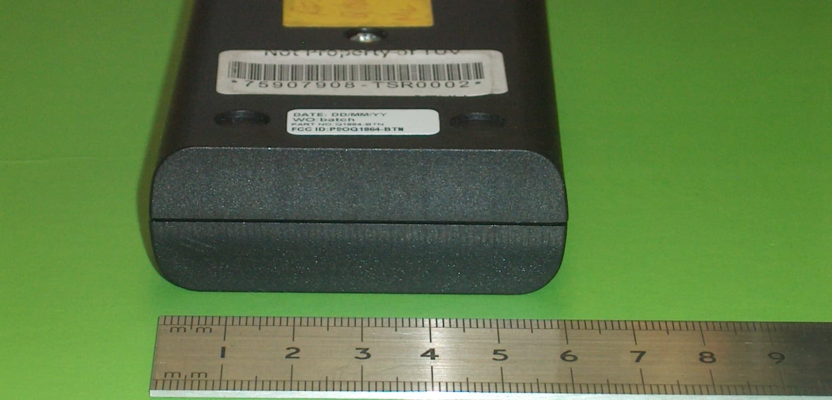
P9OQ1864-BTN
Sep 19, 2010Operator button for activating of Tensator Q1864 queue forwarding system
Equipment Class
DSR - Part 15 Remote Control/Security Device Transceiver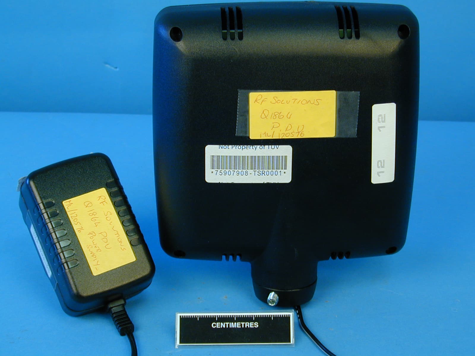
P9OQ1864-PDU
Sep 16, 2010Positional display unit for Tensator queue forwarding system
Equipment Class
DSR - Part 15 Remote Control/Security Device Transceiver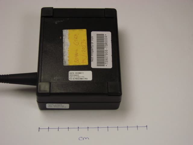
P9OQ1864-CTRX
Sep 16, 2010Central transceiver unit for Tensator E-queuing system
Equipment Class
DSR - Part 15 Remote Control/Security Device Transceiver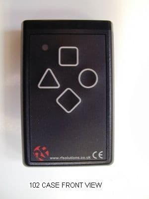
P9O102
Jan 06, 2003Radio Encoder Transmitter
Equipment Class
DSC - Part 15 Security/Remote Control Transmitter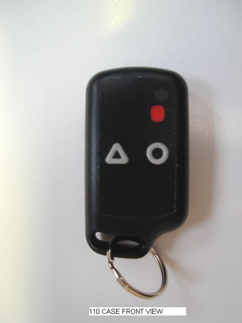
P9O110
Jan 06, 2003Keyfob Radio Encoder Transmitter
Equipment Class
DSC - Part 15 Security/Remote Control Transmitter