P9OQ1864-PDUPositional display unit for Tensator queue forwarding system
RF Solutions Ltd.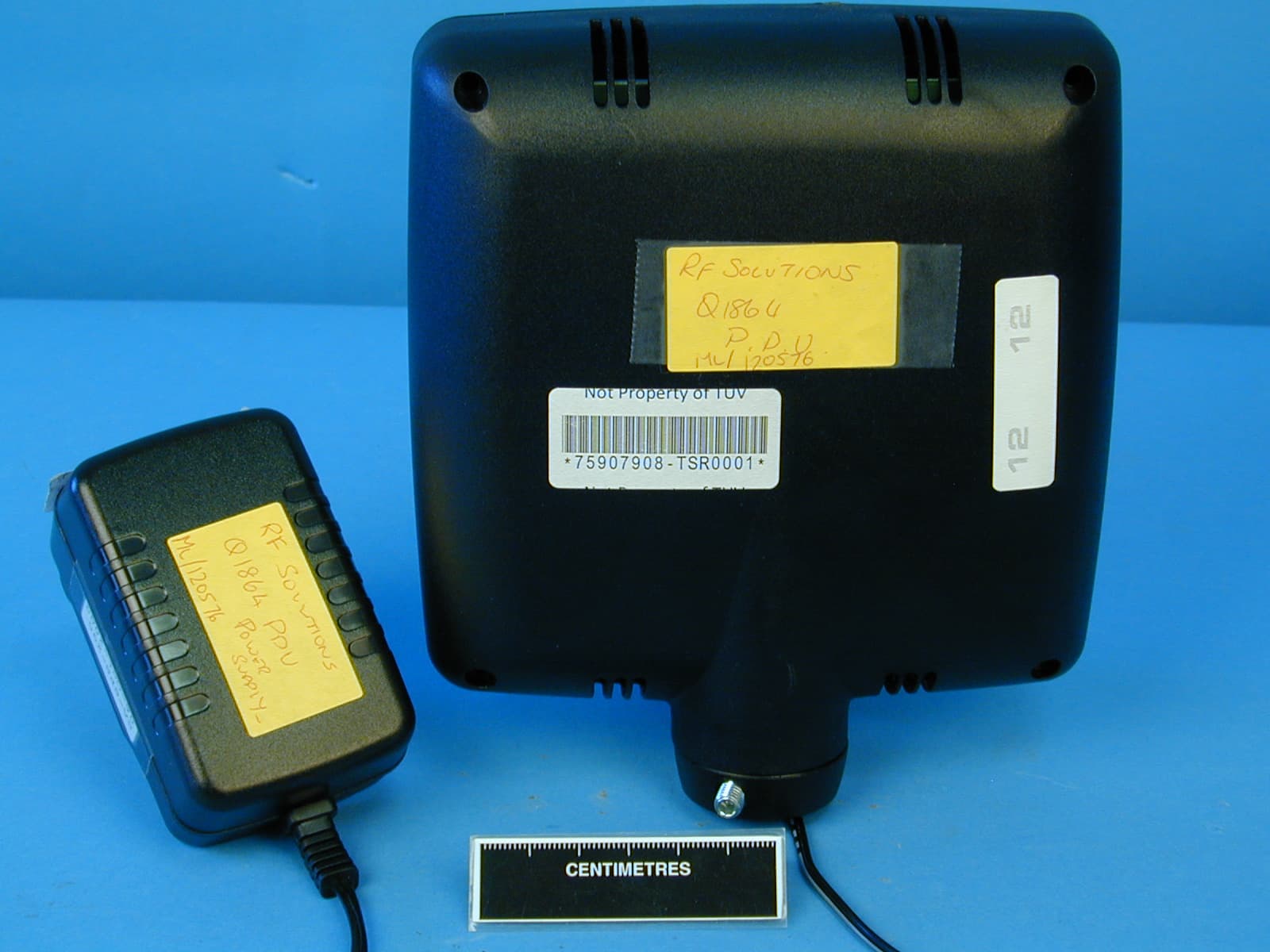
Click to zoom
Application Details
- Equipment Class
- DSR - Part 15 Remote Control/Security Device Transceiver
- Date of Grant
- Sep 16, 2010
- Application Purpose
- Original Equipment
- Date of Application
- Sep 16, 2010
- Equipment Note
- Positional display unit for Tensator queue forwarding system
- Frequency Range
- 433.92000000 - 433.92000000
- Company
- RF Solutions Ltd.
- Country
- United Kingdom
Documents & Files
Document Text
Text extracted from the exhibit documents filed with the FCC. Open a document above to read the original.
Users Manual
F o r m o r e in f o r m a t io n C a ll: +4 4 (0 ) 1 9 0 8 6 8 4 6 0 6 F a x : +4 4 (0 ) 1 9 0 8 6 8 4 7 0 0 ja m es . a u s t in @t e n s a t o r . c o m w w w . t e n s a t o r . c o m Tensator ECF Media System Tensator Wireless ECF User Guide Project Number: T01150 Document Version: 1 Date: 14th September 2009 Document Status: DRAFT T01150 - Wireless ECF User Guide.doc (c)2009 Tensator Ltd Page 2 of 10 Version History Version Date By Changes Sections 1 14/9/2009 James Austin Initial document. Contents Page 1 Brief ................................................................................................................................ 2 2 Hardware Configuration ...................................................................................................... 3 2.1 PDUs ........................................................................................................................ 3 2.2 Buttons ..................................................................................................................... 3 3 Software Configuration ....................................................................................................... 4 3.1 Programming a Button Address .................................................................................... 9 3.2 Programming a PDU Address ....................................................................................... 9 1 Brief The Tensator Wireless ECF provides both wireless data connection to PDUs and to a new generation of Tensator RF Button. The Wireless PDU provides mains connected LED PDUs with a wireless data link back to a Tensator Hub. The Tensator hub requires a CTRX (transceiver) unit to be connected. A maximum of 24 units can be connected to any one system. There are 254 different zones that can be used and these zones are used to allow multiple systems to be installed within a shared area. Wireless RF buttons share the same CTRX as the PDUs. Again, there is a maximum of 24 buttons per zone (1 zone per CTRX). The estimated operational distance is 100 meters line-of-site. Every site has slightly different RF characteristics and therefore during the installation the CTRX (transceiver) unit should be tried in different locates until the optimum position is found. T01150 - Wireless ECF User Guide.doc (c)2009 Tensator Ltd Page 3 of 10 2 Hardware Configuration A data connection to the CTRX (transceiver) and the Tensator hub is provided using USB. The unit comes with an A to B USB cable which is connected from the connector on the base of the CTRX and the Tensator hub. The CTRX will show as a serial port on the hub. There are no zone switches on either the CTRX nor the RF buttons. This is now controlled by software. 2.1 PDUs The PDUs show their serial number and the zone and address settings from switch-on. The serial is used to program the zone and address for each individual unit. Power is provided for by a two pin terminal on the reverse of the PDU electronic board. A 5V power supply is provided. The PSU comes with UK, EU and US mains adaptors. Mains is required due to the high current usage of the unit. The PDUs can also be powered if connected to a PDU Interface unit. In this case the power is supplied via the CAT5 cabling. 2.2 Buttons The button units are programmed by holding down both buttons on the unit until the left LED goes amber then releasing the buttons. This writes the buttons serial number into the configuration system on the hub. The address is then set using the configuration system and the two RF buttons must be held down again in the same way as before. This is covered in more detail in the software section. Power is provided using a 9V PP3 battery. This gives a true wireless solution for the RF buttons. Each button unit has two LEDs. LED 1 is on the top left, LED 2 is on the top right. LED 1 Functions LED 2 Functions Red – waiting reply reserved for future use Green – got reply Amber – ready to send serial Red flashing for time – low battery Software Configuration T01150 - Wireless ECF User Guide.doc (c)2009 Tensator Ltd Page 4 of 10 3 Software Configuration 1. PDUs and buttons are configured via the web interface. To access the web interface go to: http://localhost/TensatorAdmin/Login.aspx Change ‘localhost’ to a machine IP address if connecting through a network. 2. Login as TensatorAdministrator with the same password. Click on the Administration -> Hardware Configuration. T01150 - Wireless ECF User Guide.doc (c)2009 Tensator Ltd Page 5 of 10 3. CTRX Settings CTRX Zone This is the zone to use for the system. If you are setting up four systems use four different zones across the four systems. CTRX Com Port The COM port can either be manually entered or selected from the list of currently available ports on the remote machine. T01150 - Wireless ECF User Guide.doc (c)2009 Tensator Ltd Page 6 of 10 4. PDU Configuration Number of PDUs in system – Must be set to the number of PDUs that will be used for this specific configuration. PDU Number Scheme - Lists available number designs from: c:\inetpub\wwwroot\TensatorAdmin\Library\Numbers Please ensure that there are the correct number of files for the number of PDUs required. Arrow File - Lists available arrow designs from: c:\inetpub\wwwroot\TensatorAdmin\Library\Arrows Position Closed File - Lists available closed designs from: c:\inetpub\wwwroot\TensatorAdmin\Library\ClosedSigns PDU Number Direction - Select either Left to Right or Right to Left (from the perspective of the end customer). Arrow Run Mode - There are three modes to choose from as follows: No Arrows Arrows from All Positions Arrows Between CDU and Position Only Call Duration - (In seconds) The length of time to display arrows and flashing number on the PDUs. Note that this is interrupted by additional calls. T01150 - Wireless ECF User Guide.doc (c)2009 Tensator Ltd Page 7 of 10 5. PDU Mapping The PDU mapping allows PDUs to have a different number graphic assigned. So if the…
Text truncated - open the document above for the full version.
ID Label/Location Info
FCC TCF Q1864 PDU.doc Page 6 of 9 4.0 FCC Certification 4.1 FCC CFR 47 Part 15 Compliance is demonstrated in TUV Test report 75907908 report 03 Issue 1. Copy appears in Appendix C. 5.0 Electrical Safety This product is powered from the USB. in the unlikely event of a short circuit occurring within the unit, there is no risk to the heath and safety of the user and any other person . 6.0 Product Marking The date of manufacture, batch and product type are identified by the manufacturing label which includes the FCC ID:P9OQ1864-CTRX. POSITION OF FCC ID LABEL
Test Report
Document 75907908 Report 02 Issue 1 February 2010 Report On FCC Testing of the RF Solutions Ltd Tensator Display COMMERCIAL-IN-CONFIDENCE FCC ID: P9OQ1864-PDU TUV Product Service Ltd, Octagon House, Concorde Way, Segensworth North, Fareham, Hampshire, United Kingdom, PO15 5RL Tel: +44 (0) 1489 558100. Website: www.tuvps.co.uk COMMERCIAL-IN-CONFIDENCE Document 75907908 Report 02 Issue 1 Page 1 of 30 COMMERCIAL-IN-CONFIDENCE REPORT ON FCC Testing of the RF Solutions Ltd Tensator Display Document 75907908 Report 02 Issue 1 February 2010 PREPARED FOR RF Solutions Ltd Unit 21 Cliffe Industrial Estate South Street Lewes East Sussex BN8 6JL PREPARED BY N Bennett Senior Administrator APPROVED BY C Gould Authorised Signatory M J Hardy Authorised Signatory DATED 04 February 2010 ENGINEERING STATEMENT The measurements shown in this report were made in accordance with the procedures described on test pages. All reported testing was carried out on a sample equipment to demonstrate limited compliance with FCC CFR 47 Part 15. The sample tested was found to comply with the requirements defined in the applied rules. Test Engineers; G Lawler A Guy R A Blagg COMMERCIAL-IN-CONFIDENCE Document 75907908 Report 02 Issue 1 Page 2 of 30 COMMERCIAL-IN-CONFIDENCE CONTENTS Section Page No 1 REPORT SUMMARY ................................................................................................................... 3 1.1 Introduction ................................................................................................................................... 4 1.2 Brief Summary of Results ............................................................................................................. 5 1.3 Declaration of Build Status ........................................................................................................... 6 1.4 Product Information ...................................................................................................................... 7 1.5 Test Conditions ............................................................................................................................. 9 1.6 Deviations From the Standard ...................................................................................................... 9 1.7 Modification Record ...................................................................................................................... 9 2 TEST DETAILS .......................................................................................................................... 10 2.1 Radiated Emissions (Enclosure Port) ......................................................................................... 11 2.2 Conducted Emissions (AC Power Port) ...................................................................................... 17 2.3 Bandwidth of the Emissions ....................................................................................................... 22 3 TEST EQUIPMENT USED ......................................................................................................... 24 3.1 Test Equipment Used ................................................................................................................. 25 3.2 Measurement Uncertainty .......................................................................................................... 26 4 PHOTOGRAPHS ........................................................................................................................ 27 4.1 Test Set Up Photographs ........................................................................................................... 28 5 ACCREDITATION, DISCLAIMERS AND COPYRIGHT ............................................................ 29 5.1 Accreditation, Disclaimers and Copyright ................................................................................... 30 COMMERCIAL-IN-CONFIDENCE Document 75907908 Report 02 Issue 1 Page 3 of 30 COMMERCIAL-IN-CONFIDENCE SECTION 1 REPORT SUMMARY FCC Testing of the RF Solutions Ltd Tensator Display COMMERCIAL-IN-CONFIDENCE Document 75907908 Report 02 Issue 1 Page 4 of 30 COMMERCIAL-IN-CONFIDENCE 1.1 INTRODUCTION The information contained in this report is intended to show verification of the RF Solutions Ltd, Tensator Display to the requirements of FCC CFR 47 Part 15. Objective To perform FCC Testing to determine the Equipment Under Test's (EUT’s) compliance with the Test Specification, for the series of tests carried out. Manufacturer RF Solutions Ltd Model Number Q1864-PDU Serial Number(s) Not Serialised Software Version Version 1 Hardware Version Version 2 Number of Samples Tested 1 Test Specification/Issue/Date FCC CFR 47 Part 15: 2009 Incoming Release Date Declaration of Build Status 05 January 2010 Disposal Reference Number Date Held Pending Disposal Not Applicable Not Applicable Order Number Date 13465 20 October 2009 Start of Test 26 October 2009 Finish of Test 27 January 2010 Name of Engineer(s) A Guy G Lawler R A Blagg Related Document(s) ANSI C63.4: 2003 COMMERCIAL-IN-CONFIDENCE Document 75907908 Report 02 Issue 1 Page 5 of 30 COMMERCIAL-IN-CONFIDENCE 1.2 BRIEF SUMMARY OF RESULTS A brief summary of results in accordance wi th FCC CFR 47 Part 15, is shown below. Configuration 1 - Stand Alone Section Spec Clause Test Description Mode Mod State Result Base Standard 2.1 15.109 15.231 15.205 Radiated Emissions (Enclosure Port) Transmit with modulation 0 Pass - Idle 0 Pass 2.2 15.107 and15.207 Conducted Emissions (AC Power Port) Transmit with modulation 0 Pass - Idle 0 Pass 2.3 15.231 Bandwidth of the Emission Transmit with modulation 0 Pass - Idle N/A N/A – Not Applicable Documen t 1.3 D N p s N d t 75907908 R DECLARAT MAIN EUT MANUFACTU MANUFACTU TYPE PART NUMBE SERIAL NUM HARDWARE SOFTWARE V TRANSMITTE RECEIVER O COUNTRY OF INTERMEDIA ITU DESIGNA HIGHEST INT FREQUENCY OUTPUT POW FCC ID INDUSTRY CA TECHNICAL D (a brief descr operation) BATTERY/PO MANUFACTU MANUFACTU TYPE PART NUMBE …
Text truncated - open the document above for the full version.
Contact Information
Applicant
John Fairall(Director)
Technical Contact
RF Solutions LtdTom Faith
[email protected]+44 1273 898000
Unit 21, Cliffe Ind. Est. · Lewes · United Kingdom
Test Firm
TUV SUD Product ServiceMark Jenkins
Technical Specifications
| # | Rule Parts | Frequency Range | Power Output |
|---|---|---|---|
| 1 | 15.231 | 433.92 MHz - 433.92 MHz | 3.00 mW |
Other Applications from RF Solutions Ltd.
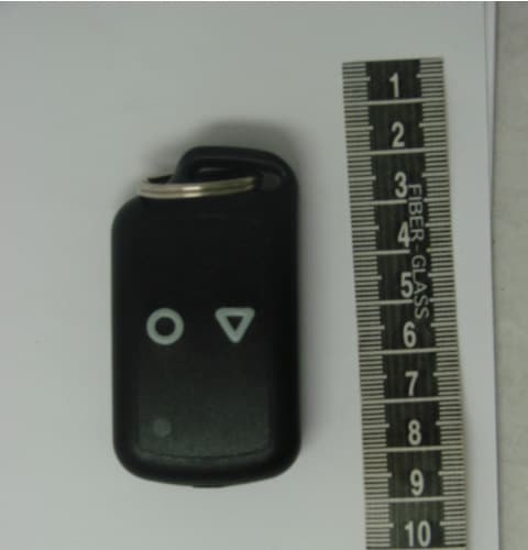
P9OHORNET-TX
Jul 31, 2011Transmitter keyfob for Hornet systems
Equipment Class
DXX - Part 15 Low Power Communication Device Transmitter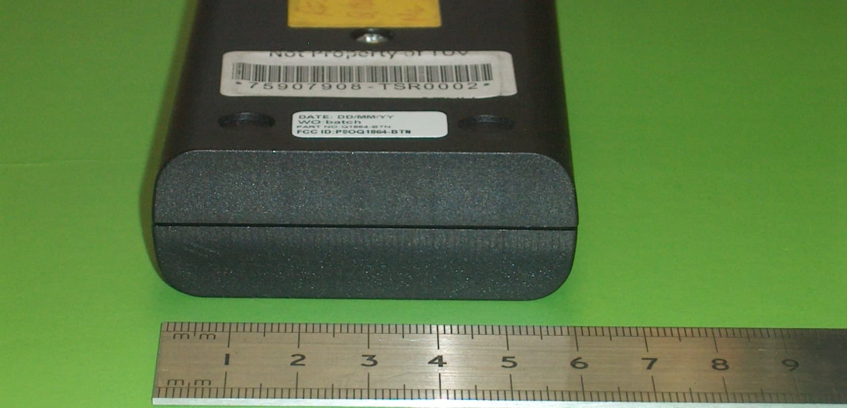
P9OQ1864-BTN
Sep 19, 2010Operator button for activating of Tensator Q1864 queue forwarding system
Equipment Class
DSR - Part 15 Remote Control/Security Device Transceiver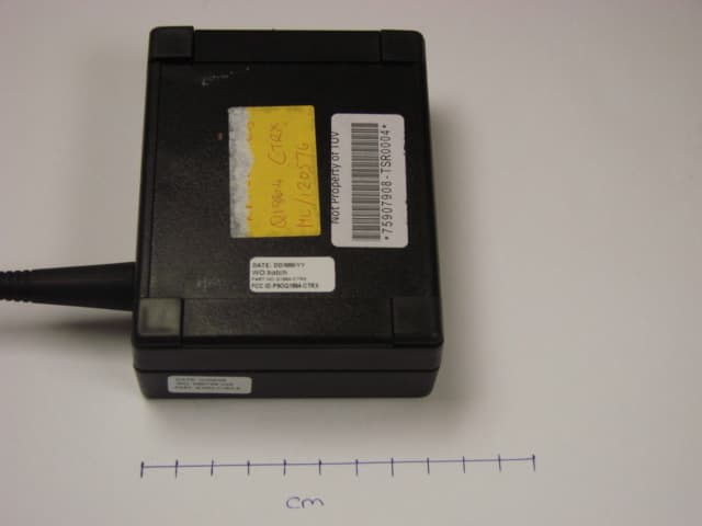
P9OQ1864-CTRX
Sep 16, 2010Central transceiver unit for Tensator E-queuing system
Equipment Class
DSR - Part 15 Remote Control/Security Device Transceiver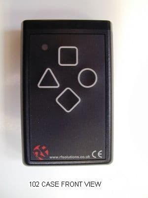
P9O102
Jan 06, 2003Radio Encoder Transmitter
Equipment Class
DSC - Part 15 Security/Remote Control Transmitter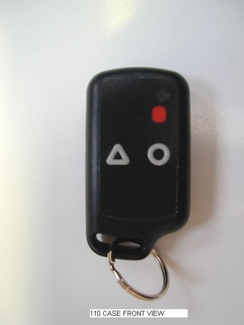
P9O110
Jan 06, 2003Keyfob Radio Encoder Transmitter
Equipment Class
DSC - Part 15 Security/Remote Control Transmitter