P9X-EMS-H200BlueMeter Hub Transceiver
Eaton's Cooper Power Systems
Click to zoom
Application Details
- Equipment Class
- DSS - Part 15 Spread Spectrum Transmitter
- Date of Grant
- Jun 10, 2002
- Application Purpose
- Original Equipment
- Date of Application
- Jun 10, 2002
- Equipment Note
- BlueMeter Hub Transceiver
- Frequency Range
- 2402.00000000 - 2480.00000000
- Company
- Eaton's Cooper Power Systems
- Country
- United States
Documents & Files
Document Text
Text extracted from the exhibit documents filed with the FCC. Open a document above to read the original.
Users Manual
6/10/02 Eka Systems Proprietary 3/18 Hardware Setup Guide Eka Systems Inc. 444 N Frederic Ave • Suite 315 • Gaithersburg, MD 20877 Phone 301.990.3450 • Fax 301.990.3451 6/10/02 Eka Systems Proprietary 4/18 STEP 1 Identify the hardware Identify the following components that are part of the BlueMeter Hub package. ß BlueMeter hub, with its attached Bluetooth dongle. ß BlueMeter Module for the electric meter. ß 5V DC adapter to power the BlueMeter hub. ß CD media with the BlueMeter TM Network Manager software. ß BlueMeter TM Network Manager User Guide. STEP 2 Configuring the IP Address on the Hub For connecting the Hub on to a LAN. Follow the procedure outlined in this step. Components required: 1. PC with Windows 95, Windows 98, Windows 2000, Windows NT and Windows XP operating system. 2. PC must have an available serial port. 3. Network Manager Software CD. 4. 9-pin female-to-female null modem cable. 5. Two Ethernet cables for LAN connectivity. 6. Configuring the PC on the local LAN. Configuring the IP address on the Hub. 1. Connect the PC on to a local LAN. 2. Install Network Manager Software on the PC. 3. Bring up the Network Manager software by selecting ‘Start- >Programs->Eka Systems->BlueMeter Network Manager- >Launch BlueMeter Network Manager’. 6/10/02 Eka Systems Proprietary 5/18 4. Connect the DC power cable (included) to the Hub. 5. Connect the other end of the DC power cable to the power outlet. 6. Connect the null modem cable to the available serial port on the PC running the Network Manager and the ‘COM2’ port on the Hub. (Null Modem cable not included). 7. Follow the steps outlined in Chapter 2 of the BlueMeter Network Manager User Guide to add a Hub using a serial port connection as shown in the picture below. 8. Once the Hub is added, double click on the Hub that is just added. 9. The user will be prompted to enter the username and password for the Hub. (Use the username and password provided with the Hardware setup guide). 10. The user will see the screen as shown in Figure 5 of the BlueMeter Network Manager User Guide. 11. Click on ‘Set Hub IP Address’ from the Advanced Configuration option. 12. The ‘Set Hub IP Address’ button allows the user to enter an IP address and a Netmask for the Hub Figure 1. Figure 1 Set IP address dialog box 13. Enter the new IP address in this dialog box and save. 14. Once the IP address is configured, the Hub may be moved and relocated to any desired spot, provided access to the LAN is available. To Verify the IP address, please perform the following: 1. Remove the null modem cable between the PC and the Hub. 2. Using the Ethernet cable, connect Hub to the local LAN drop. 3. Follow steps outlined in Chapter 2 of the BlueMeter Network Manager User Guide to ‘Configure the Hub’ to communicate over the LAN. 4. Once the Hub is configured and added in the list of Hubs (with Network option), follow steps in section 2.2 of the BlueMeter Network Manager User guide to connect to a Hub. 6/10/02 Eka Systems Proprietary 6/18 STEP 3 Install the BlueMeter Module The BlueMeter add-on card must always be installed as the innermost option board (the board closest to the kV meter’s main board). Please refer to the GEkV meter’s option board installation procedure to install the BlueMeter add-on card. If there are any other option boards, install them above the BlueMeter add-on card. STEP 4 Additional connections To access the hub from MeterMate through serial port, connect a null- modem serial cable between the COM2 port on the hub and any COM port on the PC. Please note that the serial port on the hub is configured to communicate at 9600 baud. FCC Notice This device complies with Part 15 of the FCC Rules. Operation is subject to the following two conditions: (1) this device may not cause harmful interference, and (2) this device must accept any interference received, including interference that may cause undesired operation. Changes or modifications not expressly approved by the manufacturer could void the user’s authority to operate the equipment. This equipment has been tested and found to comply with the limits for a Class B digital device, pursuant to Part 15 of the FCC Rules. These limits are designed to provide reasonable protection against harmful interference in a residential installation. This equipment generates, uses and can radiate radio frequency energy and, if not installed and used in accordance with the instructions, may cause harmful interference to radio communications. However, there is no guarantee that interference will not occur in a particular installation. If this equipment does cause harmful interference to radio or television reception, which can be determined by turning the equipment off and on, the user is encouraged to try to correct the interference by one or more of the following measures: -- Reorient or relocate the receiving antenna. -- Increase the separation between the equipment and receiver. -- Connect the equipment into an outlet on a circuit different from that to which the receiver is connected. -- Consult the dealer or an experienced radio/TV technician for help.
Block Diagram
5/9/02 Eka Systems Proprietary 7/17 Appendix C – Block Diagram of BlueMeter Hub The BlueMeter Hub is composed of two major components: an embedded computer and a wireless module. The embedded computer is configured with proprietary software. The wireless module uses a Bluetooth transceiver and interfaces to the embedded computer through an RS- 232 interface. Embedded Computer Wireless module Eka Systems proprietary software Bluetooth transceiver RS232 Line-driver RS-232 serial port
Cover Letter(s)
1) The FRN Number provided (0007-0503-05) had the following error when searched on the FCC Database: "The FRN is Inactive. Please Contact CORES administrator". Please note that we must have a valid FRN number in order to process the application. Please explain. R: Please see exhibit “Corrected Eka Hub Form 731.pdf” 2) The EUT block diagram and operational description suggest that the EUT is designed for use attached to an embedded computer, while the EUT was attached to a Hub. Please explain. (also see #3 below) R: The embedded computer is a specialized product containing Eka System’s proprietary software and is part of the overall BlueMeter HUB System. The EUT, containing the RS-232 port, will only be connected to the embedded computer and is designed only to operate with the proprietary software in the embedded computer. 3) Various exhibits mention that the device is to be attached to an embedded computer. Please comment on whether this device should also be considered as Class B or class A peripheral since it is designed with a serial interface. Please note that additional labeling information will be required for Class B DoC authorized peripherals or if the device is considered a Class A peripheral, then justification as to Class A classification should be provided. R: See response to #2. The EUT was tested to Class B Verification. 4) Please provide a better resolution copy of the label. The wording provided on the label is not easily discernible. R: Please see exhibit “Improved FCC Label.pdf” 5) The manual should also include the statements of 15.105. Please provide an updated manual. R: Manual has been updated to include the statement of 15.105. Please see exhibit “Revised Hub Manual.PDF” 6) This device utilizes a blue tooth module. We have been including the attached file with other blue tooth applications since it covers many of the regulatory requirements of 15.247 for compliance parameters that should not change for Blue Tooth devices. Please review and comment if we may include this file with your application. R: Please include this file with the application. 7) Section 2.1033(b)(5) requires a schematic for the transmitter portion of the product. Eka Systems, Inc. may not have access to this information if the RF module is designed by a different company. Please provide either a schematic for the transmitter portion of the product, or as an alternative you may provide a parts list that specifies the module as an OEM part provided by another manufacturer. R: Please see exhibit “Hub Parts List.PDF” 8) The highest output power measured was 11.2 dBm, while the operational description mentions 20 dBm. Please explain this discrepancy. R: The output power was listed incorrectly in the Operational Description. The Operational Description has been updated and lists the power as <12dBm. 9) Please confirm the instrumentation settings used during the power spectral density test. R: The test report has been amended to include the instrumentation settings used for the power spectral density measurement. Please see exhibits “Revised Test Report Part....”.pdf 10) Please provide a sample calculation for Section 4.5 of the test report. R: The test report has been amended to include the sample calculation. Please see exhibits “Revised Test Report Part....”.pdf 11) The test procedure 4.5.1 states a resolution bandwidth of < 10 Hz for average measurements above 1 GHz. The VBW should actually be 10 Hz. Please comment on the VBW used. R: A video bandwidth of 10Hz was used to make the measurements. The test report has been corrected. Please see exhibits “Revised Test Report Part....”.pdf 12) For spurious emissions, please explain if the EUT was hop-stopped. Also please explain if the transmitter for purposes of this test set to a CW signal, or was there a duty cycle associated with the TX carrier during these tests? R: Hopping was stopped during spurious emissions testing. The test report has been updated to include the configuration used during spurious emissions testing. Please see exhibits “Revised Test Report Part....”.pdf 13) Blue Tooth devices are classified as a hybrid spread spectrum device and require the processing gain as specified by 15.247(f). Please note that this requirement will be removed in the next few days when the Report and Order is published in the Federal Register (see http://hraunfoss.fcc.gov/edocs_public/attachmatch/FCC-02-151A1.pdf). R: Processing gain was not uploaded for this reason. We expect this will be published by the time the application will be uploaded.
Cover Letter(s)
American Telecommunications Certification Body Inc. 6731 Whittier Ave, McLean, VA 22101 June 5, 2002 RE: Eka Systems, Incorporated FCC ID: P9X-EMS-H200 After a review of the submitted information, I have a few comments on the above referenced Application. 1) The FRN Number provided (0007-0503-05) had the following error when searched on the FCC Database: "The FRN is Inactive. Please Contact CORES administrator". Please note that we must have a valid FRN number in order to process the application. Please explain. 2) The EUT block diagram and operational description suggest that the EUT is designed for use attached to an embedded computer, while the EUT was attached to a Hub. Please explain. (also see #3 below) 3) Various exhibits mention that the device is to be attached to an embedded computer. Please comment on whether this device should also be considered as Class B or class A peripheral since it is designed with a serial interface. Please note that additional labeling information will be required for Class B DoC authorized peripherals or if the device is considered a Class A peripheral, then justification as to Class A classification should be provided. 4) Please provide a better resolution copy of the label. The wording provided on the label is not easily discernible. 5) The manual should also include the statements of 15.105. Please provide an updated manual. 6) This device utilizes a blue tooth module. We have been including the attached file with other blue tooth applications since it covers many of the regulatory requirements of 15.247 for compliance parameters that should not change for Blue Tooth devices. Please review and comment if we may include this file with your application. 7) Section 2.1033(b)(5) requires a schematic for the transmitter portion of the product. Eka Systems, Inc. may not have access to this information if the RF module is designed by a different company. Please provide either a schematic for the transmitter portion of the product, or as an alternative you may provide a parts list that specifies the module as an OEM part provided by another manufacturer. 8) The highest output power measured was 11.2 dBm, while the operational description mentions 20 dBm. Please explain this discrepancy. 9) Please confirm the instrumentation settings used during the power spectral density test. 10) Please provide a sample calculation for Section 4.5 of the test report. 11) The test procedure 4.5.1 states a resolution bandwidth of < 10 Hz for average measurements above 1 GHz. The VBW should actually be ≥ 10 Hz. Please comment on the VBW used. 12) For spurious emissions, please explain if the EUT was hop-stopped. Also please explain if the transmitter for purposes of this test set to a CW signal, or was there a duty cycle associated with the TX carrier during these tests? 13) Blue Tooth devices are classified as a hybrid spread spectrum device and require the processing gain as specified by 15.247(f). Please note that this requirement will be removed in the next few days when the Report and Order is published in the Federal Register (see http://hraunfoss.fcc.gov/edocs_public/attachmatch/FCC-02-151A1.pdf). Timothy R. Johnson Examining Engineer mailto: [email protected] The items indicated above must be submitted before processing can continue on the above referenced application. Failure to provide the requested information may result in application termination. Correspondence should be considered part of the permanent submission and may be viewed from the Internet after a Grant of Equipment Authorization is issued. Please do not respond to this correspondence using the email reply button. In order for your response to be processed expeditiously, you must submit your documents through the AmericanTCB.com website. Also, please note that partial responses increase processing time and should not be submitted. Any questions about the content of this correspondence should be directed to the sender.
Cover Letter(s)
444 N. Frederick Ave l Suite 315 l Gaithersburg Maryland 20872 l Phone 301.990.3450 l Fax 301.990.3451 l www.ekasystems.com June 26, 2002 American Telecommunications Certification Body, Inc. 6731 Whittier Avenue Suite C110 McLean, VA 22101 RE: Certification Application FCC ID: P9X-EMS-H200 Please be advised that the following exhibits are be held confidential on behalf of Eka Systems, Inc.: • Schematics • Parts List The application contains technical information that Eka Systems, Inc. deems to be trade secrets and proprietary. If made public, the information might be used to the disadvantage of the applicant in the market place. Thank you for your attention to this matter. Michael Babst V.P. of Operations Eka Systems, Inc. MB:BTM
External Photos
Exterior Photos BlueMeter Hub with Typical Router I/O Port Antenna Left Side Right Side Bottom
ID Label/Location Info
FCC Label for Eka Systems BlueMeter Hub FCC ID: P9X-EMS-H200 This device complies with Part 15 of the FCC Rules. Operation is subject to the following two conditions: (1) this device may not cause harmful interference, and (2) this device must accept any interference received, including interference that may cause undesired operation.
Internal Photos
Hub Module Cover Removed PCB Top PCB Bottom Internal Antenna Board, Front Internal Antenna Board, Back Bluetooth Module
Operational Description
MITSUMI Bluetooth TM Module WML-C07 OUTLINE Wireless communication module conforming to Bluetooth Ver. 1.1. This product was Bluetooth standard certified in November, 2001. Applications include notebook PCs, PC peripheral equipment such as printers and terminal adapters, and various other types of equipment. * The "Bluetooth" trademarks are owned by Telefonaktiebolaget LM Ericsson, Sweden. Telecommunication component SPECIFICATIONS FEATURES 1. Ultra-small and thin size achieved through use of high density mounting technology. 2. Simple installation on the main unit, using only two screws. 3. High sensitivity supports communications of up to 100m. 4. UART, USB and PCMIF interfaces enable wide range of applications. 5. Conforms to FCC, CE and other countries'EMI standards. 6. Supports Bluetooth Class1 (CLASS 2-supporting WML-C06 also available). 7. Uses connector to connect to main unit. ItemSpecifications Frequency2402 to 2480MHz Modulation FHSS/GFSK Channel intervals 1MHz Number of channels 79CH Power suppIy voltage3.3±0.1V Transmission rate 721kbps Receive sensitivity -80dBm typ. Output level (Class1) 20dBm max. MITSUMI DIMENSIONS Bluetooth TM Module Unit : mm * For the technical details of the products in this page, please refer to Sales promotion Dept., TOCHIGI MITSUMI Co., Ltd. Phone: 0283 (23) 3332. 14.7 ± 0.2 (7.5) (16) (5.45) (2.5) (2.8) (13.35) 2.55 +0.3 0 (9.25) (12.45) (10.25) (12) 32 ±0.3 15 +0.6 0 13.4 ±0.3 15 4.5 5 ± 0.2 4.5 14 ±0.3 15 2.5 ± 0.2 0.8) (t= 2.1 2.1 1.05 R 1.05 R U.FL-R-SMT(HIROSE) CO-AXIAL RF CONNECTOR AXK6F22545J (Panasonic) CONNECTOR 12 22 1 11 TERMINALS 1. GND12. VDDc 2. UART_RX13. UART_CTS/USB_D- 3. SPI_MISO14. UART_RTS/USB_D+ 4. SPI_CLK15. UART_TX 5. SPI_MOSI16. PIO [3] /USB_WAKE_UP 6. PIO [4] /USB_ON17. PIO [2] /USB_PULL_UP 7. SPI_CSB18. PIO [7] 8. PCM_CLK19. PCM_SYNC 9. PIO [5] /USB_DETACH20. PCM_IN 10. PIO [6] 21. PCM_OUT 11. VDD_PA22. RESET_IN (NC)
Operational Description
Sansei Electric Co., Ltd. Antenna Information Rotary type Operating frequency : 2.4GHz2.5GHz VSWR : 1.5max Band (VSWR2.0 : 300MHz Input impedance : 50 Ù maximum gain (Horizontal plane) : 0 dBd Average gain (Horizontal plane) : -1.3 dBd Size (mm) : 110 (Main parts length) *A standard cable connector is included.
Operational Description
6/13/02 Eka Systems Proprietary 11/18 Appendix F – Theory of Operation 1. Components The BlueMeter Hub is composed of two major components: an embedded computer and a wireless module. The embedded computer is configured with Eka Systems proprietary software, so that a user may program the computer to perform tasks automatically or interactively. The wireless module uses a Bluetooth transceiver and interfaces to the embedded computer through an RS-232 interface. Using the Bluetooth transceiver, the embedded computer communicates wirelessly with other Eka Systems devices. The wireless module is permanently attached to a serial port on the embedded computer. Besides the Bluetooth transceiver, the wireless module contains line-driving components to interface the serial port with the Bluetooth transceiver. The Bluetooth transceiver has a maximum transmit power of 20 dBm and is compliant with the Bluetooth Specifications, Version 1.1. 2. Operations The BlueMeter Hub communicates and collects data from up to 64 electricity meters. At start up the radio receiver on the Hub is activated. The Hub initially discovers wireless meters within its range. A wireless network administrator may assign a meter to a BlueMeter Hub by designating a managed status to the Hub. For each managed meter, Hub collects data transmitted by the meter. The Hub also calculates and stores interval data. A proprietary application software allows configuring the Hub to detect and report network status alarms, power failures, communications failures and low battery alarms. The application software also maintains logs and displays network alarms and network events. Another application software communicates with the Hub and provides energy management information to the end-user. For example, the information includes, energy usage, peak demand, load duration and power quality. This information provides insight to various aspects of a utility bills including, energy charges, demand charges, and peak usage charges. The connection may be over a serial cable or over Ethernet. The user may select a meter managed by the Hub and request an on-demand meter read. For interval data collection, the end-user identifies frequency of interval data collection for each of the desired meter. Once the interval collection is defined for a meter, the application software collects interval data at those intervals. The collected data may be listed in a tabular or graphical format. Figure 1 shows the setup of the BlueMeter Hub. 6/13/02 Eka Systems Proprietary 12/18 Figure 1: Setup of the BlueMeter Hub 3. Radio Functions The BlueMeter Hub uses a Bluetooth transceiver for data transportation over the air. Bluetooth is a set of wireless specifications that can be mapped to the ISO Open System Interconnection (OSI) Reference Model in the manner shown in Figure 2. Figure 2: OSI reference model and the full Bluetooth protocol stack It is also possible to use only a partial set of the full Bluetooth functionalities in the manner shown in Figure 3; the BlueMeter Hub uses the Bluetooth transceiver only for data transportation and falls into this category. TCS/RFCOMM/SDP Application Presentation Session Transportation Network Data Link Physical Baseband RF Link Manager Application Host Controller Interface Link Controller OSI Reference Model Partial Bluetooth protocol stack Logical Link Control and Adaption Protocol Meter 123456 kWh Meter 123456 kWh Meter 123456 kWh Network PC BlueMeter Hub 6/13/02 Eka Systems Proprietary 13/18 Figure 3: OSI reference model and partial Bluetooth protocol stack The following six sections describe the functions of each layer of the Bluetooth protocols used by the BlueMeter Hub. 3.1 RF Layer The Bluetooth radio performs spectrum spreading by frequency hopping in 79 frequencies that are displaced by 1 MHz, between 2.402GHz and 2.480GHz. The maximum transmit power is <12 dBm, but the actual transmitted power on a link may be lower for optimization. The modulation uses GFSK (Gaussian Frequency Shift Keying) where a binary one is represented by a positive frequency deviation and a binary zero by a negative frequency deviation. The BT (Time-Bandwidth product) is 0.5 and the modulation index is between 0.28 and 0.35. The frequency synthesizer changes frequency between receive slot and transmit slot, but always returns to the same transmit frequency. The transmitted initial center frequency accuracy must be ±75 kHz from center. The receiver has a sensitivity level of -70dBm or better to achieve a bit error rate (BER) of 0.1% or better. The interference performance on co-channel and adjacent 1 MHz and 2 MHz are measured with the wanted signal 10 dB over the reference sensitivity level. On all other frequencies, the wanted signal is 3 dB over the reference sensitivity level. The out of band blocking is measured with the wanted signal 3 dB over the reference sensitivity level. The interfering signal is a continuous wave signal. The BER is less than or equal to 0.1%. The reference sensitivity performance, BER = 0.1%, is met under the following conditions: • The wanted signal at frequency f 0 with a power level 6 dB over the reference sensitivity level; Application Presentation Session Transportation Network Data Link Physical Baseband RF Link Manager Application Host Controller Interface Link Controller OSI Reference Model Partial Bluetooth protocol stack Logical Link Control and Adaption Protocol 6/13/02 Eka Systems Proprietary 14/18 • A static sine wave signal at f 1 with a power level of -39 dBm; • A Bluetooth modulated signal at f 2 with a power level of -39 dBm; and • f 0 = 2f 1 - f 2 and |f 2 - f 1 | = n MHz, where n can be 3, 4, or 5. 3.2 Baseband Layer The baseband is responsible for hop selection, low-level timing control, channel coding and decoding, and management of the link within the domain of a single data packet transfer. The frequency channel on which to transmit is chosen among the 79 frequencies according to a pseudo-rando…
Text truncated - open the document above for the full version.
RF Exposure Info
Document 6959-MPE, Rev. 0 FCC ID: P9X-EMS-H200 RF Exposure Test Report Washington Laboratories, Ltd May 2002 Maximum Permissible Exposure Test Report for Eka Systems, Inc. BlueMeter HUB FCC ID: P9X-EMS-H200 May 2002 WLL PROJECT #: 6959X This report may not be reproduced, except in full, without the prior written consent of Washington Laboratories, Ltd. RF Exposure Test Report Document 6959-MPE, Rev. 0 FCC ID: P9X-EMS-H200 RF Exposure Test Report Washington Laboratories, Ltd May 2002 1 Maximum Permissible Exposure Test Report for FCC ID: P9X-EMS-H200 1.0 Introduction This report has been prepared on behalf of Eka Systems, Inc. Model: BlueMeter HUB Bluetooth transmitter to show compliance with the RF exposure requirements as defined in FCC §1.1307. 1.1 Requirements Three different categories of transmitters are defined by the FCC in OET Bulletin 65. These categories are fixed installation, mobile, and portable and are defined as follows: ß Fixed Installations: fixed location means that the device, including its antenna, is physically secured at a permanent location and is not able to be easily moved to another location. ß Mobile Devices: a mobile device is defined as a transmitting device designed to be used in other than fixed locations and to be generally used in such a way that a separation distance of at least 20 centimeters is normally maintained between the transmitter's radiating structures and the body of the user or nearby persons. Transmitters designed to be used by consumers or workers that can be easily re-located, such as a wireless modem operating in a laptop computer, are considered mobile devices if they meet the 20 centimeter separation requirement. The FCC rules for evaluating mobile devices for RF compliance are found in 47 CFR §2.1091. ß Portable Devices: a portable device is defined as a transmitting device designed to be used so that the radiating structure(s) of the device is/are within 20 centimeters of the body of the user. Portable device requirements are found in Section 2.1093 of the FCC's Rules (47 CFR§2.1093). For this test report the Eka Systems BlueMeter HUB is classified as a “Mobile” device and therefore must meet the limits as specified in §1.307. The FCC also categorizes the use of the device as based upon the user’s awareness and ability to exercise control over his or her exposure. The two categories defined are Document 6959-MPE, Rev. 0 FCC ID: P9X-EMS-H200 RF Exposure Test Report Washington Laboratories, Ltd May 2002 2 Occupational/Controlled Exposure and General Population/Uncontrolled Exposure. These two categories are defined as follows: ß Occupational/Controlled Exposure: In general, occupational/controlled exposure limits are applicable to situations in which persons are exposed as a consequence of their employment, who have been made fully aware of the potential for exposure and can exercise control over their exposure. This exposure category is also applicable when the exposure is of a transient nature due to incidental passage through a location where the exposure levels may be higher than the general population/uncontrolled limits, but the exposed person is fully aware of the potential for exposure and can exercise control over his or her exposure by leaving the area or by some other appropriate means. Awareness of the potential for RF exposure in a workplace or similar environment can be provided through specific training as part of a RF safety program. If appropriate, warning signs and labels can also be used to establish such awareness by providing prominent information on the risk of potential exposure and instructions on methods to minimize such exposure risks. ß General Population/Uncontrolled Exposure: The general population / uncontrolled exposure limits are applicable to situations in which the general public may be exposed or in which persons who are exposed as a consequence of their employment may not be made fully aware of the potential for exposure or cannot exercise control over their exposure. Members of the general public would come under this category when exposure is not employment-related; for example, in the case of a wireless transmitter that exposes persons in its vicinity. Warning labels placed on low-power consumer devices such as cellular telephones are not considered sufficient to allow the device to be considered under the occupational/controlled category, and the general population/uncontrolled exposure limits apply to these devices. Since there are no warnings or training associated with this unit and it can be used by anyone, the Eka Systems BlueMeter HUB is evaluated to the General Population/Uncontrolled Exposure limits. 1.2 Radio Frequency Radiation Exposure Evaluation The highest RF output power of the unit was measured at 11.2dBm at 2441 MHz. According to §1.1310 of the FCC rules, the power density limit for General Population/Uncontrolled Exposure is 1mW/cm 2 . To comply with the exposure limits for this section, individuals must maintain a safe distance from the transmit antenna. The following formula was used to calculate the minimum safe distance: 2 4R PG S π = Where: Document 6959-MPE, Rev. 0 FCC ID: P9X-EMS-H200 RF Exposure Test Report Washington Laboratories, Ltd May 2002 3 S = Power Density P = Output Power at the Antenna Terminals G = Gain of Transmit Antenna (linear gain) R = Distance from Transmitting Antenna For this device, the calculation is as follows: S = FCC Limit = 1mW/cm 2 P = Output Power = 13.1mW G = Worst Case Gain = 2.15dBi = INVLOG(2.15/10) = 1.64 Solving for the required minimum safe distance using the following formula: S PG R π4 = 14 64.11.13 ×× × = π R = 1.3 cm (Based on continuous transmission) Based on the calculation above, the device complies with the minimal permissible exposure requirements well within the 20cm distance for mobile devices.
Test Report
Document 6959-01, Rev. 0 FCC ID: P9X-EMS-H200 FCC Certification Test Report Washington Laboratories, Ltd May 2002 FCC Certification Test Report for Eka Systems, Inc. FCC ID: P9X-EMS-H200 May 31, 2002 Prepared for: Eka Systems, Inc. 444 N. Frederick Avenue, Suite 315 Gaithersburg, MD 20877 Prepared By: Washington Laboratories, Ltd. 7560 Lindbergh Drive Gaithersburg, Maryland 20879 FCC Certification Test Report Document 6959-01, Rev. 0 FCC ID: P9X-EMS-H200 FCC Ce…
Text truncated - open the document above for the full version.
Contact Information
Applicant
Steven Seymour(Certification Engineer)
Technical Contact
Washington Laboratories, Ltd.Gregory M Snyder
[email protected]301-417-0220
7560 Lindbergh Drive · Gaithersburg, Maryland · United States
Non-Technical Contact
Washington Laboratories, Ltd.Brian J Dettling
[email protected]301-417-0220
Test Firm
Washington Laboratories, Ltd.Michael Violette
Technical Specifications
| # | Rule Parts | Frequency Range | Power Output |
|---|---|---|---|
| 1 | 15C | 2.40 GHz - 2.48 GHz | 13.10 mW |
Other Applications from Eaton's Cooper Power Systems
P9X-410CL
Jul 16, 2013RFN-410CL
Equipment Class
DSS - Part 15 Spread Spectrum Transmitter
P9X-430SL
Jun 18, 2013RFN-430SL
Equipment Class
DSS - Part 15 Spread Spectrum Transmitter
P9X-420CL1WNZ
Jan 09, 2013RFN 420CL(1W, NZ) Module
Equipment Class
DSS - Part 15 Spread Spectrum Transmitter
P9X-420CL1W
Jan 09, 2013Utility Meter Reading Transmitter
Equipment Class
DSS - Part 15 Spread Spectrum Transmitter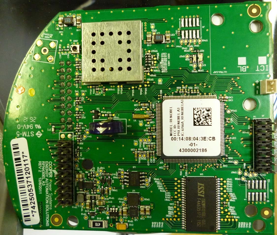
P9X-430ELA31W
Nov 25, 2012RFN 430EL-A3 (1W)
Equipment Class
DSS - Part 15 Spread Spectrum Transmitter