P9X-EMS-MM-GEElectric Meter with BlueMeter Transmitter
Eaton's Cooper Power Systems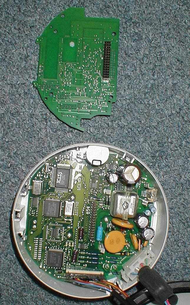
Click to zoom
Application Details
- Equipment Class
- DSS - Part 15 Spread Spectrum Transmitter
- Date of Grant
- Sep 05, 2002
- Application Purpose
- Original Equipment
- Date of Application
- Sep 05, 2002
- Equipment Note
- Electric Meter with BlueMeter Transmitter
- Frequency Range
- 2402.00000000 - 2480.00000000
- Company
- Eaton's Cooper Power Systems
- Country
- United States
Documents & Files
Document Text
Text extracted from the exhibit documents filed with the FCC. Open a document above to read the original.
Users Manual
Eka Systems Proprietary Hardware Setup Guide Eka Systems Inc. 444 N Frederick Ave • Suite 315 • Gaithersburg, MD 20877 Phone 301.990.3450 • Fax 301.990.3451 Eka Systems Proprietary STEP 1 Identify the hardware Identify the following components that are part of the BlueMeter Hub package. ß BlueMeter hub, with its attached Bluetooth dongle. ß BlueMeter Module for the electric meter. ß 5V DC adapter to power the BlueMeter hub. ß CD media with the BlueMeter TM Network Manager software. ß BlueMeter TM Network Manager User Guide. STEP 2 Configuring the IP Address on the Hub For connecting the Hub on to a LAN. Follow the procedure outlined in this step. Components required: 1. PC with Windows 95, Windows 98, Windows 2000, Windows NT and Windows XP operating system. 2. PC must have an available serial port. 3. Network Manager Software CD. 4. 9-pin female-to-female null modem cable. 5. Two Ethernet cables for LAN connectivity. 6. Configuring the PC on the local LAN. Configuring the IP address on the Hub. 1. Connect the PC on to a local LAN. 2. Install Network Manager Software on the PC. 3. Bring up the Network Manager software by selecting ‘Start- >Programs->Eka Systems->BlueMeter Network Manager- >Launch BlueMeter Network Manager’. Eka Systems Proprietary 4. Connect the DC power cable (included) to the Hub. 5. Connect the other end of the DC power cable to the power outlet. 6. Connect the null modem cable to the available serial port on the PC running the Network Manager and the ‘COM2’ port on the Hub. (Null Modem cable not included). 7. Follow the steps outlined in Chapter 2 of the BlueMeter Network Manager User Guide to add a Hub using a serial port connection as shown in the picture below. 8. Once the Hub is added, double click on the Hub that is just added. 9. The user will be prompted to enter the username and password for the Hub. (Use the username and password provided with the Hardware setup guide). 10. The user will see the screen as shown in Figure 5 of the BlueMeter Network Manager User Guide. 11. Click on ‘Set Hub IP Address’ from the Advanced Configuration option. 12. The ‘Set Hub IP Address’ button allows the user to enter an IP address and a Netmask for the Hub Figure 1. Figure 1 Set IP address dialog box 13. Enter the new IP address in this dialog box and save. 14. Once the IP address is configured, the Hub may be moved and relocated to any desired spot, provided access to the LAN is available. To Verify the IP address, please perform the following: 1. Remove the null modem cable between the PC and the Hub. 2. Using the Ethernet cable, connect Hub to the local LAN drop. 3. Follow steps outlined in Chapter 2 of the BlueMeter Network Manager User Guide to ‘Configure the Hub’ to communicate over the LAN. 4. Once the Hub is configured and added in the list of Hubs (with Network option), follow steps in section 2.2 of the BlueMeter Network Manager User guide to connect to a Hub. STEP 3 Install the BlueMeter Module The BlueMeter add-on card must always be installed as the innermost option board (the board closest to the kV meter’s main board). Please refer to the GEkV meter’s option board installation procedure to install the BlueMeter add-on card. If there are any other option boards, install them above the BlueMeter add-on card. In accordance with the labeling requirements of the FCC, the identity of the BlueMeter card must be visible after the installation of the GEkV meter. This can be done by placing a label with the following information on the meter in a location that is visible after installation. STEP 4 Additional connections To access the hub from MeterMate through serial port, connect a null- modem serial cable between the COM2 port on the hub and any COM port FCC ID: P9X-EMS-MM-GE Eka Systems Proprietary on the PC. Please note that the serial port on the hub is configured to communicate at 9600 baud. FCC Notice This device complies with Part 15 of the FCC Rules. Operation is subject to the following two conditions: (1) this device may not cause harmful interference, and (2) this device must accept any interference received, including interference that may cause undesired operation. Changes or modifications not expressly approved by the manufacturer could void the user’s authority to operate the equipment. Information to the User This equipment has been tested and found to comply with the limits for a Class B digital device, pursuant to Part 15 of the FCC Rules. These limits are designed to provide reasonable protection against harmful interference in a residential installation. This equipment generates, uses and can radiate radio frequency energy and, if not installed and used in accordance with the instructions, may cause harmful interference to radio communications. However, there is no guarantee that interference will not occur in a particular installation. If this equipment does cause harmful interference to radio or television reception, which can be determined by turning the equipment off and on, the user is encouraged to try to correct the interference by one or more of the following measures: • Reorient or relocate the receiving antenna. • Increase the separation between the equipment and receiver. • Connect the equipment into an outlet on a circuit different from that to which the receiver is connected. • Consult the dealer or an experienced radio/TV technician for help. RF Exposure Warning As the BlueMeter contains a radio frequency transmitter RF energy is present and caution must be used when installing the unit and during normal usage. A safe distance of 20cm from the antenna of the device must be maintained during normal operation. The BlueMeter must be installed in the GEkV meter to maintain this safe distance. Additionally, the BlueMeter must not be co-located or operating in conjunction with any other antenna or transmitter
Block Diagram
5/15/02 Eka Systems Proprietary 7/16 Appendix C – Block Diagram of BlueMeter Meter Module The BlueMeter Meter Module has four major components: microprocessor, memories, meter interface, and wireless unit. The microprocessor is an IC that controls the operations of the meter module. The memories are ICs that retain operation data. The meter interface is buffering circuitry for communication with the meter. The wireless unit uses a Bluetooth transceiver for wireless communication with other BlueMeter devices. BlueMeter Meter Module Bluetooth transceiver Meter Interface Memories Micro- processor Meter
Cover Letter(s)
Response to ATCB Comments 1 Washington Laboratories, Ltd. 7560 LINDBERGH DRIVE GAITHERSBURG, MD 20879 (301) 417 – 0220 FAX # (301) 417 - 9069 August 30, 2002 Mr. Tim Johnson American Telecommunications Certification Body Inc. 6731 Whittier Ave McLean, VA 22101 RE: Comments of August 1, 2002 APPLICATION: P9X-EMS-MM-GE Eka Systems, Inc. Dear Mr. Johnson: Below are the comments that you have provided regarding the application for certification referenced above. Our responses to those comments are in bold italic. Many responses refer you to additional exhibit(s) which has been uploaded to the application folder at the ATCB website. Thank you for your attention. Please feel free to contact us for any additional information that you may require. Regards, Gregory M. Snyder Chief EMC Engineer, Wireless/Telco Services Manager Brian J. Dettling Documentation Specialist WLL Project: 7044 August 1, 2002 RE: Eka Systems, Inc. FCC ID: P9X-EMS-MM-GE 1) Please confirm that confidentiality is NOT requested on the parts list. If Eka Systems wishes to request on this exhibit, please update the confidentiality letter. R. The letter has been updated. Please see exhibit “Revised RFC Letter.pdf”. Response to ATCB Comments 2 2) Please provide external photograph that show the EUT as tested, a photograph showing placement of the board inside the device, additional photographs to show the general construction of the internal portion of the meter the device was tested within, and a clear photograph of the back of the TX module. R. Please see exhibits “Meter Test Fixture.pdf”, “Additional EUT Photo.pdf”. 3) The Theory of Operations/Users Manual discusses this transmitter board being an accessory board installed in an electric meter. Please provide information regarding what meter(s) this will be installed within (Test Report lists General Electric kV Vector). If Eka Systems wishes this filing to be representative of multiple meters, then this fact should be clearly represented in the application and detailed information provided as to the construction variances between the meters (and justify why they do/do not affect EMI). Depending on the construction differences, test data may be required for each model, or at least to obtained in order to determine the worse case model. Without this information, the filing can only cover the product as tested. Construction difference between meter makes will likely require a permissive change. Please let me know how you wish to handle this issue. R. The Test Report has been updated to describe the BlueMeter as a modular device to be installed only for use in the General Electric kV Vector meter as tested. Please see exhibit “Revised Module Test Report.pdf”. 4) The submittal seems to partially support a modular approval but does not request this, provide the necessary information for modular approvals, nor was the sample tested in a stand alone configuration. The operational description mentions the board as an accessory board (retrofitting?). This also tends to suggest a modular approval. A limited modular approval (LMA) may be a suggestive course of action here but does not appear to be requested or tested as such. Please comment. R. The BlueMeter is to be approved as a device for integration into new GE kV Vector electric meters. 5) Please explain if this device is offered for sale only as an upgrade, or will it also be sold already installed in a meter. R. The device is to be sold as tested in the GE kV Vector meter. 6) The labeling information should also include the statements required by 15.19(a)(3) R. As the unit is installed in the electric meter, the required labeling has been included in the manual. Please see exhibit “Revised User Guide.pdf”. 7) From the photographs provided and the labeling information, it is not clear where the label is placed relative to the whole device and if it is readable from the outside of the device. Please provide further information and/or photographs. R. Instructions have been included in the manual to include the FCC identifier label in a location that may be visible after installation. A label location graphic has been provided. Please see exhibit “FCC Label Location- Meter Exterior.pdf”. 8) I have a concern with the label if it can't be viewed from the outside. The “two part” label [15.19(a)(3)] will never be seen by the end user unless he disassembles his electric meter. This is an Response to ATCB Comments 3 unlikely event. The device is larger than the palm of your hand, therefore I expect there should be easily enough “real estate” to place label on outside. R. Per our discussions it was determined that since the unit is installed in the electric meter, the required labeling could be included in the manual. 9) In addition, if “retrofitting” is permitted, how does the Applicant propose to meet the labeling requirements? R. The BlueMeter module is not intended to be retrofitted into service meters already in use. The unit is only to be installed as “OEM” in new meters. 10) Devices of this type are typically classified as mobile, but the RF exposure information classifies the device as a 'fixed' device. 'Fixed' requires that the user maintain 2 meters between humans/users and the antenna. Given the output power and antenna gain information, it might be better to consider the device as a mobile transmitter (>20 cm from antenna). Otherwise, please justify how 2 meter will always be maintained for RF exposure compliance. R. The MPE document has been revised to list the device as a Mobile instead of a Fixed installation. Please see exhibit “MPE Report Rev 1.pdf”. 11) The users manual should include RF exposure information such as (sample given is for mobile classification): "NOTE: The antenna used for this transmitter must be installed to provide a separation distance of at least 20 cm from all persons and must not be co-located or operating in conjunction with any other antenna or transmitter." R. The User’s Manual has been updated to i…
Text truncated - open the document above for the full version.
Cover Letter(s)
Response to ATCB Comments 1 Washington Laboratories, Ltd. 7560 LINDBERGH DRIVE GAITHERSBURG, MD 20879 (301) 417 – 0220 FAX # (301) 417 - 9069 September 5, 2002 Mr. Tim Johnson American Telecommunications Certification Body Inc. 6731 Whittier Ave McLean, VA 22101 RE: Comments of September 2, 2002 APPLICATION: P9X-EMS-MM-GE Eka Systems, Inc. Dear Mr. Johnson: Below are the comments that you have provided regarding the application for certification referenced above. Our responses to those comments are in bold italic. Many responses refer you to additional exhibit(s) which has been uploaded to the application folder at the ATCB website. Thank you for your attention. Please feel free to contact us for any additional information that you may require. Regards, Gregory M. Snyder Chief EMC Engineer, Wireless/Telco Services Manager Brian J. Dettling Documentation Specialist WLL Project: 7044 September 2, 2002 RE: Eka Systems, Inc. FCC ID: P9X-EMS-MM-GE 1) Please provide photograph of the back of the Bluetooth TX module. R. Please see exhibit “Additional EUT Photograph.pdf” that was uploaded in response to Item 1 of your comments of August 1, 2002. 2) The device is classified as a mobile device. Therefore the RF exposure information should specify a 20 cm distance in the users manual based on its classification. MPE calculations of course show that Response to ATCB Comments 2 the device easily meets at a closer distance. Please adjust the users manual so that the RF exposure information states 20 cm. 3) From your response a modular approval is not being pursued. Therefore the labeling on the outside of the meter will be for the entire device and not just the transmitter board. Please update the labeling on the outside of the device and the references made by the users manual (i.e. do not reference "Contains" in the labeling). 4) The users manual appears to be for part of a system. Since the device is installed in equipment used at subscribers facilities (see 15.103(b)), the users information specified in 15.105 be included in the manual. R. The Users Manual has been revised to address comments 2 through 4 above. Please see exhibit “Revised User Manual 9.05.02.pdf.”
Cover Letter(s)
American Telecommunications Certification Body Inc. 6731 Whittier Ave, McLean, VA 22101 August 1, 2002 RE: Eka Systems, Inc. FCC ID: P9X-EMS-MM-GE After a review of the submitted information, I have a few comments on the above referenced Application. 1) Please confirm that confidentiality is NOT requested on the parts list. If Eka Systems wishes to request on this exhibit, please update the confidentiality letter. 2) Please provide external photograph that show the EUT as tested, a photograph showing placement of the board inside the device, additional photographs to show the general construction of the internal portion of the meter the device was tested within, and a clear photograph of the back of the TX module. 3) The Theory of Operations/Users Manual discusses this transmitter board being an accessory board installed in an electric meter. Please provide information regarding what meter(s) this will be installed within (Test Report lists General Electric kV Vector). If Eka Systems wishes this filing to be representative of multiple meters, then this fact should be clearly represented in the application and detailed information provided as to the construction variances between the meters (and justify why they do/do not affect EMI). Depending on the construction differences, test data may be required for each model, or at least to obtained in order to determine the worse case model. Without this information, the filing can only cover the product as tested. Construction difference between meter makes will likely require a permissive change. Please let me know how you wish to handle this issue. 4) The submittal seems to partially support a modular approval but does not request this, provide the necessary information for modular approvals, nor was the sample tested in a stand alone configuration. The operational description mentions the board as an accessory board (retrofitting?). This also tends to suggest a modular approval. A limited modular approval (LMA) may be a suggestive course of action here but does not appear to be requested or tested as such. Please comment. 5) Please explain if this device is offered for sale only as an upgrade, or will it also be sold already installed in a meter. 6) The labeling information should also include the statements required by 15.19(a)(3) 7) From the photographs provided and the labeling information, it is not clear where the label is placed relative to the whole device and if it is readable from the outside of the device. Please provide further information and/or photographs. 8) I have a concern with the label if it can't be viewed from the outside. The “two part” label [15.19(a)(3)] will never be seen by the end user unless he disassembles his electric meter. This is an unlikely event. The device is larger than the palm of your hand, therefore I expect there should be easily enough “real estate” to place label on outside. 9) In addition, if “retrofitting” is permitted, how does the Applicant propose to meet the labeling requirements? 10) Devices of this type are typically classified as mobile, but the RF exposure information classifies the device as a 'fixed' device. 'Fixed' requires that the user maintain 2 meters between humans/users and the antenna. Given the output power and antenna gain information, it might be better to consider the device as a mobile transmitter (>20 cm from antenna). Otherwise, please justify how 2 meter will always be maintained for RF exposure compliance. 11) The users manual should include RF exposure information such as (sample given is for mobile classification): "NOTE: The antenna used for this transmitter must be installed to provide a separation distance of at least 20 cm from all persons and must not be co-located or operating in conjunction with any other antenna or transmitter." 12) The users manual appears to be for part of a system. Shouldn't the users information specified in 15.105 be included in the manual? z Page 2August 1, 2002 -Continued on Next Page - 13) The information in this submittal mentions that the Blue Tooth Module is capable of +20 dBm, but has been set to +10 dBm. Please confirm that the power is not adjustable in the field or by the end-user. 14) The peak radiated data does not appear to calculate properly in the tables, please explain. Timothy R. Johnson Examining Engineer mailto: [email protected] The items indicated above must be submitted before processing can continue on the above referenced application. Failure to provide the requested information may result in application termination. Correspondence should be considered part of the permanent submission and may be viewed from the Internet after a Grant of Equipment Authorization is issued. Please do not respond to this correspondence using the email reply button. In order for your response to be processed expeditiously, you must submit your documents through the AmericanTCB.com website. Also, please note that partial responses increase processing time and should not be submitted. Any questions about the content of this correspondence should be directed to the sender.
Cover Letter(s)
American Telecommunications Certification Body Inc. 6731 Whittier Ave, McLean, VA 22101 September 2, 2002 RE: Eka Systems, Inc. FCC ID: P9X-EMS-MM-GE After a review of the submitted information, I have a few comments on the above referenced Application. 1) Please provide photograph of the back of the Bluetooth TX module. 2) The device is classified as a mobile device. Therefore the RF exposure information should specify a 20 cm distance in the users manual based on its classification. MPE calculations of course show that the device easily meets at a closer distance. Please adjust the users manual so that the RF exposure information states 20 cm. 3) From your response a modular approval is not being pursued. Therefore the labeling on the outside of the meter will be for the entire device and not just the transmitter board. Please update the labeling on the outside of the device and the references made by the users manual (i.e. do not reference "Contains" in the labeling). 4) The users manual appears to be for part of a system. Since the device is installed in equipment used at subscribers facilities (see 15.103(b)), the users information specified in 15.105 be included in the manual. Timothy R. Johnson Examining Engineer mailto: [email protected] The items indicated above must be submitted before processing can continue on the above referenced application. Failure to provide the requested information may result in application termination. Correspondence should be considered part of the permanent submission and may be viewed from the Internet after a Grant of Equipment Authorization is issued. Please do not respond to this correspondence using the email reply button. In order for your response to be processed expeditiously, you must submit your documents through the AmericanTCB.com website. Also, please note that partial responses increase processing time and should not be submitted. Any questions about the content of this correspondence should be directed to the sender.
Cover Letter(s)
444 N. Frederick Ave l Suite 315 l Gaithersburg Maryland 20872 l Phone 301.990.3450 l Fax 301.990.3451 l www.ekasystems.com July 26, 2002 American Telecommunications Certification Body, Inc. 6731 Whittier Avenue Suite C110 McLean, VA 22101 RE: Certification Application FCC ID: P9X-EMS-MM-GE Please be advised that the following exhibits are be held confidential on behalf of Eka Systems, Inc.: • Schematics • Parts List The application contains technical information that Eka Systems, Inc. deems to be trade secrets and proprietary. If made public, the information might be used to the disadvantage of the applicant in the market place. Thank you for your attention to this matter. Michael Babst V.P. of Operations Eka Systems, Inc. MB:BTM
External Photos
Electric Service Meter (GE) Test Fixture Interior of Meter with Eka Tx Module In Place Inter of Meter with Eka Tx Module Removed
ID Label/Location Info
FCC Label Location, Electric Service Meter (GE)
ID Label/Location Info
5/15/02 Eka Systems Proprietary 6/16 Appendix B – Label Artwork
Internal Photos
Module Top View BlueTooth Module Removed Module Bottom Bluetooth with Shield Removed
Operational Description
MITSUMI Bluetooth TM Module WML-C07 OUTLINE Wireless communication module conforming to Bluetooth Ver. 1.1. This product was Bluetooth standard certified in November, 2001. Applications include notebook PCs, PC peripheral equipment such as printers and terminal adapters, and various other types of equipment. * The "Bluetooth" trademarks are owned by Telefonaktiebolaget LM Ericsson, Sweden. Telecommunication component SPECIFICATIONS FEATURES 1. Ultra-small and thin size achieved through use of high density mounting technology. 2. Simple installation on the main unit, using only two screws. 3. High sensitivity supports communications of up to 100m. 4. UART, USB and PCMIF interfaces enable wide range of applications. 5. Conforms to FCC, CE and other countries'EMI standards. 6. Supports Bluetooth Class1 (CLASS 2-supporting WML-C06 also available). 7. Uses connector to connect to main unit. ItemSpecifications Frequency2402 to 2480MHz Modulation FHSS/GFSK Channel intervals 1MHz Number of channels 79CH Power suppIy voltage3.3±0.1V Transmission rate 721kbps Receive sensitivity -80dBm typ. Output level (Class1) 20dBm max. MITSUMI DIMENSIONS Bluetooth TM Module Unit : mm * For the technical details of the products in this page, please refer to Sales promotion Dept., TOCHIGI MITSUMI Co., Ltd. Phone: 0283 (23) 3332. 14.7 ± 0.2 (7.5) (16) (5.45) (2.5) (2.8) (13.35) 2.55 +0.3 0 (9.25) (12.45) (10.25) (12) 32 ±0.3 15 +0.6 0 13.4 ±0.3 15 4.5 5 ± 0.2 4.5 14 ±0.3 15 2.5 ± 0.2 0.8) (t= 2.1 2.1 1.05 R 1.05 R U.FL-R-SMT(HIROSE) CO-AXIAL RF CONNECTOR AXK6F22545J (Panasonic) CONNECTOR 12 22 1 11 TERMINALS 1. GND12. VDDc 2. UART_RX13. UART_CTS/USB_D- 3. SPI_MISO14. UART_RTS/USB_D+ 4. SPI_CLK15. UART_TX 5. SPI_MOSI16. PIO [3] /USB_WAKE_UP 6. PIO [4] /USB_ON17. PIO [2] /USB_PULL_UP 7. SPI_CSB18. PIO [7] 8. PCM_CLK19. PCM_SYNC 9. PIO [5] /USB_DETACH20. PCM_IN 10. PIO [6] 21. PCM_OUT 11. VDD_PA22. RESET_IN (NC)
Operational Description
11.May.2001 Technical Manual for Chip Multilayer Antenna Application: 2.4GHz Wireless Bluetooth™ Multilayer Products Department Murata Manufacturing Co., Ltd. MURATA MFG. CO.,LTD. All information contained here is subject to change without prior notice. 1 / 18 Chip Antenna is a special component to change characteristics and this requires a different matching circuit by the condition of your usage (i.e. size of PCB / the position of antenna / feeding position ...) and it is difficult to offer standard product to you. So, we prepared the below 8 different kinds of standard chip antennas which have different frequency and these will cover conditions of various customer's usage and applications of 2.4GHz. Please evaluate and find the best chip antenna out of these chip antennas. This application manual was prepered to offer advice of chip antenna's usage and technical information and this will be helpful for you to design your PCB and matching circuit. Center Frequency [MHz] New Part Number Old Part Number 2780 LDA 92 2G78 20D -204 LDA 8220D 2780A 2870 LDA 92 2G87 20D -206 LDA 8220D 2870A 2970 LDA 92 2G97 20D -208 LDA 8220D 2970A 3050 LDA 92 3G05 20D -210 LDA 8220D 3050A 3150 LDA 92 3G15 20D -193 LDA 8220D 3150A 3240 LDA 92 3G24 20D -194 LDA 8220D 3240A 3350 LDA 92 3G35 20D -195 LDA 8220D 3350A 3500 LDA 92 3G50 20D -215 LDA 8220D 3500A MURATA MFG. CO.,LTD. All information contained here is subject to change without prior notice. 2 / 18 1. Standard f0 of LDA92****20D for 2.45GHz-Band 1-1. Measurement System Chip antenna f0 is measured by using a PCB as shown below and a network analyzer. A ferrite sheet is spread under the PCB to reduce outside influences. LDA92****20D Mount Chip Antenna Any Matching Required Attach SMA Connector 50 Ohm Feedline Ground No Ground Standard PCB for LDA92****20D (*Note: This PCB is not optimized for good gain performance.) Network Analyzer Cable Antenna Ferrite Sheet Measurement System for Chip Antenna MURATA MFG. CO.,LTD. All information contained here is subject to change without prior notice. 3 / 18 1-2. Standard f0 of LDA92****20D Center Frequency [MHz] New Part Number Old Part Number 2780LDA 92 2G78 20D -204LDA 8220D 2780A 2870LDA 92 2G87 20D -206LDA 8220D 2870A 2970LDA 92 2G97 20D -208LDA 8220D 2970A 3050LDA 92 3G05 20D -210LDA 8220D 3050A 3150LDA 92 3G15 20D -193LDA 8220D 3150A 3240LDA 92 3G24 20D -194LDA 8220D 3240A 3350LDA 92 3G35 20D -195LDA 8220D 3350A 3500LDA 92 3G50 20D -215LDA 8220D 3500A Standard f0 of LDA92****20D for 2.45GHz-Band Feed Point 2 2 9.5 Top Pad Capacitor Pad used for center frequency adjustment by laser trimming at Murata factory Appearance LDA 92 3G24 20 D -194 Chip Antenna Size Height: 20 = 2.0mm Non-GND Type Center Frequency (MHz) ID Part Number Number MURATA MFG. CO.,LTD. All information contained here is subject to change without prior notice. 4 / 18 LDA922G7820D LDA922G8720D LDA922G9720D LDA923G0520D LDA923G1520D LDA923G2420D LDA923G3520D LDA923G5020D Return Loss of Standard LDA92****20D MURATA MFG. CO.,LTD. All information contained here is subject to change without prior notice. 5 / 18 2. Suitable PCB Condition of LDA92****20D 2-1. Chip Antenna Position Excellent Good Acceptable Not recommended 2-2. Antenna Direction & Feed Point Position Good Acceptable Not recommended Open terminal of chip antenna is pointed to outside of PCB, and feed point is located at the edge of PCB. Open terminal of chip antenna is pointed to outside of PCB, however feed point is located at the inside of PCB. Feed point is located at the edge of PCB, however open terminal of chip antenna is pointed to GND plane of PCB. No GND GND No GND GND No GND GND No GND GND No GND GND No GND GND Feed Point GND No GND No GND GND No GND GND GND GND No GND GND Chip antenna is sticking out. Chip antenna is located on the no GND area. Chip antenna is located on the GND plane. LDA9220D MURATA MFG. CO.,LTD. All information contained here is subject to change without prior notice. 6 / 18 2-3. Matching Circuit Position Good Acceptable 2-4. Structure of Matching Circuit Good Good Acceptable LDA9220D RF Module 50ohm Line OUTPUT Matching Circuit LDA9220D RF Module OUTPUT Matching Circuit 50ohm Line Matching Circuit is located at the top of 50ohm line that is nearest place from chip antenna. Matching Circuit is located at the top of 50ohm line that is farthest place from chip antenna. Matching Circuit (Series-Shunt-Series) (Shunt-Series-Shunt) Matching Circuit Matching Circuit (Series-Shunt) (*Note: When series components are not needed, 0-ohm resistance is needed to mount there.) MURATA MFG. CO.,LTD. All information contained here is subject to change without prior notice. 7 / 18 2-5. Actual Mock-up PCB (1) Cellular Phone Size Semi-rigid cable should be soldered to GND plane and be extended away from the center of the PCB. And typically, ferrite beads are affixed to the part of the cable that extends away from PCB. 35 120 GND A Board Thickness ÅF 0.8 Board Material ÅF FR-4 (Close-up of A area) 11 4 2 GND No GND Area (unitÅFmm) Feed Point Matching Circuit (Top View)(Side View) Chip Antenna Ferrite Beads Semi-rigid Cable MURATA MFG. CO.,LTD. All information contained here is subject to change without prior notice. 8 /…
Text truncated - open the document above for the full version.
Contact Information
Applicant
Steven Seymour(Certification Engineer)
Technical Contact
Washington Laboratories, Ltd.Gregory M Snyde
[email protected]310-417-0220
7560 Lindbergh Drive · Gaithersburg, Maryland · United States
Non-Technical Contact
Washington Laboratories, Ltd.Brian J Dettling
[email protected]310-417-0220
Test Firm
Washington Laboratories, Ltd.Michael Violette
Technical Specifications
| # | Rule Parts | Frequency Range | Power Output |
|---|---|---|---|
| 1 | 15C | 2.40 GHz - 2.48 GHz | 9.60 mW |
Other Applications from Eaton's Cooper Power Systems
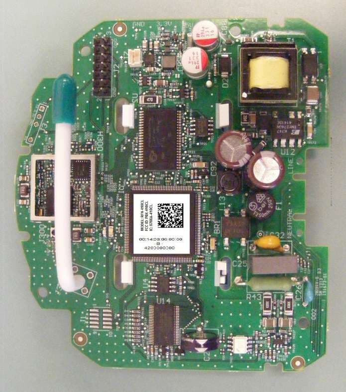
P9X-410CL
Jul 16, 2013RFN-410CL
Equipment Class
DSS - Part 15 Spread Spectrum Transmitter
P9X-430SL
Jun 18, 2013RFN-430SL
Equipment Class
DSS - Part 15 Spread Spectrum Transmitter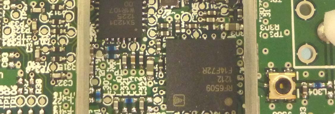
P9X-420CL1WNZ
Jan 09, 2013RFN 420CL(1W, NZ) Module
Equipment Class
DSS - Part 15 Spread Spectrum Transmitter
P9X-420CL1W
Jan 09, 2013Utility Meter Reading Transmitter
Equipment Class
DSS - Part 15 Spread Spectrum Transmitter
P9X-430ELA31W
Nov 25, 2012RFN 430EL-A3 (1W)
Equipment Class
DSS - Part 15 Spread Spectrum Transmitter