P9X2400BECR-2400 Node
Eaton's Cooper Power Systems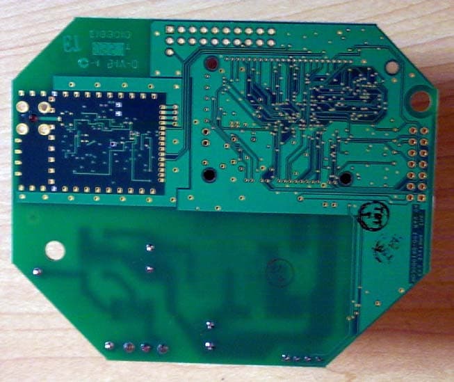
Click to zoom
Application Details
- Equipment Class
- DSS - Part 15 Spread Spectrum Transmitter
- Date of Grant
- Feb 26, 2007
- Application Purpose
- Original Equipment
- Date of Application
- Feb 26, 2007
- Equipment Note
- ECR-2400 Node
- Frequency Range
- 2402.00000000 - 2480.00000000
- Company
- Eaton's Cooper Power Systems
- Country
- United States
Documents & Files
Document Text
Text extracted from the exhibit documents filed with the FCC. Open a document above to read the original.
Users Manual
EkaNet ™ Hardware Manual Document Number 10156 Revision 07 Eka Systems, Inc. 20251 Century Boulevard, Suite 120 Germantown, MD 20874 Tel (301) 990-3450 Fax (301) 990-3451 EKA CONFIDENTIAL Confidential and Proprietary Reproduction or Distribution Prohibited This document is for informational purposes only. It contains information that is confidential and proprietary. This document has been prepared by and is the property of Eka Systems, Inc. By accepting and reviewing this document, you agree that you will treat its contents as confidential and proprietary, and that you will not copy, distribute or otherwise disclose the information contained herein to third parties. Table of Contents EkaNet Hardware Manual10156-07 Eka Proprietary and Confidential Table of Contents 1.Introduction . . . . . . . . . . . . . . . . . . . . . . . . . . . . . . . . . . . . . . . . . . . . . . . . . . . . 1 - 1 1.1Overview . . . . . . . . . . . . . . . . . . . . . . . . . . . . . . . . . . . . . . . . . . . . . . . . . . . . . . 1 - 1 1.1.1Product Highlights . . . . . . . . . . . . . . . . . . . . . . . . . . . . . . . . . . . . . . . . . 1 - 1 1.2Supporting Documents . . . . . . . . . . . . . . . . . . . . . . . . . . . . . . . . . . . . . . . . . . . . 1 - 2 1.3Version History . . . . . . . . . . . . . . . . . . . . . . . . . . . . . . . . . . . . . . . . . . . . . . . . . . 1 - 2 2.ECR-2400 Node Hardware . . . . . . . . . . . . . . . . . . . . . . . . . . . . . . . . . . . . . . . . . 2 - 1 2.1Overview . . . . . . . . . . . . . . . . . . . . . . . . . . . . . . . . . . . . . . . . . . . . . . . . . . . . . . 2 - 3 2.1.1ECR-2400 Node Features . . . . . . . . . . . . . . . . . . . . . . . . . . . . . . . . . . . 2 - 3 2.1.2ECR-2400 Node Layout . . . . . . . . . . . . . . . . . . . . . . . . . . . . . . . . . . . . 2 - 4 2.2Installation and Operation . . . . . . . . . . . . . . . . . . . . . . . . . . . . . . . . . . . . . . . . . 2 - 5 2.2.1What the Blinking Lights Mean . . . . . . . . . . . . . . . . . . . . . . . . . . . . . . . 2 - 5 2.2.1.1 The Green LED . . . . . . . . . . . . . . . . . . . . . . . . . . . . . . . . . . . . . 2 - 5 2.2.1.2 The Red LED . . . . . . . . . . . . . . . . . . . . . . . . . . . . . . . . . . . . . . 2 - 5 2.3ECR-2400 Node Specifications . . . . . . . . . . . . . . . . . . . . . . . . . . . . . . . . . . . . . 2 - 6 3.Elster A3/Alpha Plus Node Hardware. . . . . . . . . . . . . . . . . . . . . . . . . . . . . . . . 3 - 1 3.1Overview . . . . . . . . . . . . . . . . . . . . . . . . . . . . . . . . . . . . . . . . . . . . . . . . . . . . . . 3 - 3 3.1.1Elster A3/Alpha Plus Node Features . . . . . . . . . . . . . . . . . . . . . . . . . . . 3 - 4 3.1.2Elster A3/Alpha Plus Node Layout . . . . . . . . . . . . . . . . . . . . . . . . . . . . 3 - 4 3.2Installation and Operation . . . . . . . . . . . . . . . . . . . . . . . . . . . . . . . . . . . . . . . . . 3 - 5 3.2.1What the Blinking Lights Mean . . . . . . . . . . . . . . . . . . . . . . . . . . . . . . . 3 - 6 3.2.1.1 The Green LED . . . . . . . . . . . . . . . . . . . . . . . . . . . . . . . . . . . . . 3 - 6 3.2.1.2 The Red LED . . . . . . . . . . . . . . . . . . . . . . . . . . . . . . . . . . . . . . 3 - 6 3.3Elster A3/Alpha Plus Node Specifications . . . . . . . . . . . . . . . . . . . . . . . . . . . . . 3 - 7 4.RESI-MON Node Hardware . . . . . . . . . . . . . . . . . . . . . . . . . . . . . . . . . . . . . . . . 4 - 1 4.1Overview . . . . . . . . . . . . . . . . . . . . . . . . . . . . . . . . . . . . . . . . . . . . . . . . . . . . . . 4 - 2 4.1.1RESI-MON Node Features . . . . . . . . . . . . . . . . . . . . . . . . . . . . . . . . . . 4 - 2 4.1.2RESI-MON Node Layout . . . . . . . . . . . . . . . . . . . . . . . . . . . . . . . . . . . . 4 - 3 4.2Installation and Operation . . . . . . . . . . . . . . . . . . . . . . . . . . . . . . . . . . . . . . . . . 4 - 4 4.2.1What the Blinking Lights Mean . . . . . . . . . . . . . . . . . . . . . . . . . . . . . . . 4 - 4 4.2.1.1 The Green LED . . . . . . . . . . . . . . . . . . . . . . . . . . . . . . . . . . . . . 4 - 4 4.2.1.2 The Red LED . . . . . . . . . . . . . . . . . . . . . . . . . . . . . . . . . . . . . . 4 - 4 4.3RESI-MON Node Specifications . . . . . . . . . . . . . . . . . . . . . . . . . . . . . . . . . . . . 4 - 5 5.EkaNet Pulse Node Hardware . . . . . . . . . . . . . . . . . . . . . . . . . . . . . . . . . . . . . . 5 - 1 5.1Overview . . . . . . . . . . . . . . . . . . . . . . . . . . . . . . . . . . . . . . . . . . . . . . . . . . . . . . 5 - 2 5.1.1EkaNet Pulse Node Features . . . . . . . . . . . . . . . . . . . . . . . . . . . . . . . . 5 - 2 Table of Contents 10156-07EkaNet Hardware Manual Eka Proprietary and Confidential 5.2EkaNet Indoor Pulse Nodes . . . . . . . . . . . . . . . . . . . . . . . . . . . . . . . . . . . . . . . . 5 - 3 5.2.1Layout . . . . . . . . . . . . . . . . . . . . . . . . . . . . . . . . . . . . . . . . . . . . . . . . . . 5 - 3 5.2.2Connection and Operation . . . . . . . . . . . . . . . . . . . . . . . . . . . . . . . . . . . 5 - 4 5.3EkaNet Outdoor Pulse Nodes . . . . . . . . . . . . . . . . . . . . . . . . . . . . . . . . . . . . . . 5 - 5 5.3.1Layout . . . . . . . . . . . . . . . . . . . . . . . . . . . . . . . . . . . . . . . . . . . . . . . . . . 5 - 5 5.3.2Connection and Operation . . . . . . . . . . . . . . . . . . . . . . . . . . . . . . . . . . . 5 - 6 5.4What the Blinking Lights Mean . . . . . . . . . . . . . . . . . . . . . . . . . . . . . . . . . . . . . . 5 - 7 5.4.1The Green LED . . . . . . . . . . . . . . . . . . . . . . . . . . . . . . . . . . . . . . . . . . . 5 - 7 5.4.2The Red LED . . . . . . . . . . . . . . . . . . . . . . . . . . . . . . . . . . . . . . . . . . . . . 5 - 7 5.5EkaNet Pulse Node Specifications . . . . . . . . . . . . . . . . . . . . . . . . . . . . . . . . . . . 5 - 8 6.Gateway Hardware . . . . . . . . . . . . . . . . . . . . . . . . . . . . . . . . . . . . . . . . . . . . . . . 6 - 1 6.1Overview . . . . . . . …
Text truncated - open the document above for the full version.
Block Diagram
Block Diagram The block diagram of the 2400B Module is shown below. 9. 6 kbps m e ter interf ace 38. 4 kbps ser i al interf ace 2400B Module Bandpass filter Tx /Rx switch L o w noise am p. Power am p. 26 M H z crystal Data/control interface 38.4 kbps Bluetooth transceiver RAM 15 M H z addr ess & data bus 32. 768 kHz crystal 100 kHz I 2 C interf ace Host m i cr ocontr o ller 32. 768 kHz crystal Realti m e clock
Cover Letter(s)
Response to ATCB Comments FCC ID: P9X2400B 1 Washington Laboratories, Ltd. 7560 LINDBERGH DRIVE GAITHERSBURG, MD 20879 (301) 417 – 0220 FAX # (301) 417 - 9069 January 16, 2007 Mr. Tim Johnson American Telecommunications Certification Body Inc. 6731 Whittier Ave McLean, VA 22101 RE: Comments of December 21, 2006 APPLICATION: P9X2400B EKA Systems, Inc. Dear Mr. Johnson: Below are the comments that you have provided regarding the application for certification referenced above. Our responses to those comments are in bold italic. Many responses refer you to additional exhibit(s) which has been uploaded to the application folder at the ATCB website. Thank you for your attention. Please feel free to contact us for any additional information that you may require. Regards, Michael Violette President Brian J. Dettling Documentation Specialist WLL Project: 9335 1) This device appears to be modular in nature, but a modular request cover letter addressing the modular requirements does not appear to have been provided. See provided exhibit. Please review/explain. R. Please see “2400B Cover Letter – Modular”. 2) Users Manual does not appear to address appropriate RF exposure information (i.e. 20 cm and non- co-location limitation). R. The User Manual has been revised. Please see “2400B User Manual rev 1”. Response to ATCB Comments FCC ID: P9X2400B 2 3) Given this is modular and appears to normally be positioned upright, was the device placed in various axis to obtain worse case results? Test photos appear to show the board laying down, but typical use appears to be upright. R. We attest that the unit was tested in all three orthogonal planes. Worst-case data was reported, and the test setup photos represent the typical test arrangement. 4) Please adjust the 731 form to report the appropriate power. R. The form has been corrected. Please see “2400B Application Form - 731 rev 1”.
Cover Letter(s)
American Telecommunications Certification Body Inc. 6731 Whittier Ave, McLean, VA 22101 January 22, 2007 RE: Eka Systems, Inc. FCC ID: P9X2400B After a review of the submitted information, I have a few comments on the above referenced Application. 1) The FCC ID specified in the manual is not correct (pg 10). Additionally, the FCC on page 11 & 12 appears to show the FCC ID with a lower case “b”. The FCC ID must consist of only upper case letters. Also, the FCC ID appears to be in several sections of the manual which appear to apply to other devices (page 17). Please review/correct. Timothy R. Johnson Examining Engineer mailto: [email protected] The items indicated above must be submitted before processing can continue on the above referenced application. Failure to provide the requested information may result in application termination. Correspondence should be considered part of the permanent submission and may be viewed from the Internet after a Grant of Equipment Authorization is issued. Please do not respond to this correspondence using the email reply button. In order for your response to be processed expeditiously, you must submit your documents through the AmericanTCB.com website. Also, please note that partial responses increase processing time and should not be submitted. Any questions about the content of this correspondence should be directed to the sender.
Cover Letter(s)
Hi Tim, As stated in the previous response, the graphic is representative of the device (they are old photos and apparently can't be revised) and should not be taken as presenting the FCC ID. The correct ID is indicated on pages 10 and 17, as well as the presented FCC Label exhibit. The same FCC ID is applicable under the modular approval. Sorry if I'm overstating the obvious - at this point I'm not sure what else you are looking to see. Perhaps you can give me a call when you get a chance and help me to understand better what is needed. Thanks! Brian -----Original Message----- From: Timothy R. Johnson [mailto:[email protected] ] Sent: Tuesday, February 20, 2007 9:16 PM To: Brian Dettling Cc: [email protected]; ATCB- Susan Holman Subject: RE: Review of Eka Systems, Inc., FCC ID: P9X2400B after recent uploads Brian, Unless I am missing something, I do not see any changes to Page 10 & 12 or 17.....Still lower case "b" (11 and 12). As for page 17, this may be a different device - but appears this FCC ID may not be correct.... Tim
Operational Description
11/14/06 Circuit Description and Operation The module consists of a host microcontroller which serves as the central controller for the module and a radio transceiver subsystem. The host microcontroller communicates with external systems through a serial interface. Moreover, a pulse interface, through which dry contact closure pulses can be input to the host microcontroller for counting and storing is also provided. This pulse interface enables the module to be connected to, for example, energy measurement devices which output pulses in proportion to energy consumed. The host microcontroller is also provided with RAM memory to store program and data. Address and data bus connections, operating at 15Mhz enable the host microcontroller to store in and retrieve data from the RAM. A real-time clock (RTC) that keeps the time of the day is also provided. The host microcontroller communicates with the RTC through an I 2 C interface which operates at 100kHz. Oscillators provided in the host microcontroller portion of the circuitry are: a) a 32.768Mhz clock that serves as the master clock for the host microcontroller and b) a 32.768kHz clock for the RTC. The radio transceiver subsystem consists of a radio transceiver chip and front-end RF circuitry. In particular, the radio transceiver chip is an FCC Part 15 compliant off-the-shelf Bluetooth product (see the Bill of Material included in the submission). The Bluetooth radio performs spectrum spreading by frequency hopping in 79 frequencies that are displaced by 1 MHz, between 2.402GHz and 2.480GHz. The eventual maximum transmit power at the antenna is 20 dBm, but the actual transmitted power on a link may be lower for optimization. The modulation uses GFSK (Gaussian Frequency Shift Keying) where a binary one is represented by a positive frequency deviation and a binary zero by a negative frequency deviation. The Time-Bandwidth (BT) product is 0.5 and the modulation index is between 0.28 and 0.35. The frequency synthesizer changes frequency between receive slot and transmit slot, but always returns to the same transmit frequency. The transmitted initial center frequency accuracy must be ±75 kHz from center. The frequency channel on which to transmit is chosen among the 79 frequencies according to a pseudo-random hopping sequence. The channel is divided into time slots. Each slot is 625 μs in length and corresponds to a hop frequency. A time division duplexing (TDD) scheme is used where master and slave alternatively transmit. Specifically, the time slots are numbered according to the Bluetooth clock of the master, who starts its transmission in even-numbered time slots only, while the slave starts its transmission in odd-numbered time slots only. The packet start is aligned with the slot start. The receiver has a sensitivity level of -70dBm or better to achieve a bit error rate (BER) of 0.1% or better. The interference performance on co-channel and adjacent 1 MHz and 2 MHz are Eka Systems Proprietary 1/2 11/14/06 Eka Systems Proprietary 2/2 measured with the wanted signal 10 dB over the reference sensitivity level. On all other frequencies, the wanted signal is 3 dB over the reference sensitivity level. The out of band blocking is measured with the wanted signal 3 dB over the reference sensitivity level. The interfering signal is a continuous wave signal. The BER is less than or equal to 0.1%. The reference sensitivity performance, BER = 0.1%, is met under the following conditions: • The wanted signal at frequency f 0 with a power level 6 dB over the reference sensitivity level; • A static sine wave signal at f 1 with a power level of -39 dBm; • A Bluetooth modulated signal at f 2 with a power level of -39 dBm; and • f 0 = 2f 1 - f 2 and |f 2 - f 1 | = n MHz, where n can be 3, 4, or 5. The front-end RF circuitry consists of a power amplifier that boosts the output power, a low noise amplifier that serves as pre-amplifier in the receive path, a transmit/receive switch to multiplex transmit and receive paths, a front-end filter to improve rejection of out-of-band signals and an antenna. The antenna for the 2400B module is a quarter wave monopole wire antenna soldered directly on the 2400B module.
RF Exposure Info
Document 9335-MPE, Rev. 1 FCC ID: P9X2400B RF Exposure Evaluation Washington Laboratories, Ltd December 2006 Maximum Permissible Exposure Evaluation for EKA Systems EKA Meter Module ECR-2400 FCC ID: P9X2400B December 12, 2006 WLL PROJECT #: 9335 This report may not be reproduced, except in full, without the prior written consent of Washington Laboratories, Ltd. RF Exposure Evaluation Document 9335-MPE, Rev. 1 FCC ID: P9X2400B RF Exposure Evaluation Washington Laboratories, Ltd December 2006 1 Maximum Permissible Exposure Evaluation for FCC ID: P9X2400B 1.0 Introduction This report has been prepared on behalf of EKA Systems Model: EKA Meter Module ECR-2400 Transmitter to show compliance with the RF exposure requirements as defined in FCC §1.1307. 1.1 Requirements Three different categories of transmitters are defined by the FCC in OET Bulletin 65. These categories are fixed installation, mobile, and portable and are defined as follows: Fixed Installations: fixed location means that the device, including its antenna, is physically secured at a permanent location and is not able to be easily moved to another location. Additionally, distance to humans from the antenna is maintained to at least 2 meters. Mobile Devices: a mobile device is defined as a transmitting device designed to be used in other than fixed locations and to be generally used in such a way that a separation distance of at least 20 centimeters is normally maintained between the transmitter's radiating structures and the body of the user or nearby persons. Transmitters designed to be used by consumers or workers that can be easily re-located, such as a wireless modem operating in a laptop computer, are considered mobile devices if they meet the 20 centimeter separation requirement. The FCC rules for evaluating mobile devices for RF compliance are found in 47 CFR §2.1091. Portable Devices: a portable device is defined as a transmitting device designed to be used so that the radiating structure(s) of the device is/are within 20 centimeters of the body of the user. Portable device requirements are found in Section 2.1093 of the FCC's Rules (47 CFR§2.1093). For this Evaluation the EKA Systems EKA Meter Module ECR-2400 is classified as a “Mobile Device” and therefore must meet the limits as specified in §1.307. The FCC also categorizes the use of the device as based upon the user’s awareness and ability to exercise control over his or her exposure. The two categories defined are Occupational/Controlled Exposure and General Population/Uncontrolled Exposure. These two categories are defined as follows: Document 9335-MPE, Rev. 1 FCC ID: P9X2400B RF Exposure Evaluation Washington Laboratories, Ltd December 2006 2 Occupational/Controlled Exposure: In general, occupational/controlled exposure limits are applicable to situations in which persons are exposed as a consequence of their employment, who have been made fully aware of the potential for exposure and can exercise control over their exposure. This exposure category is also applicable when the exposure is of a transient nature due to incidental passage through a location where the exposure levels may be higher than the general population/uncontrolled limits, but the exposed person is fully aware of the potential for exposure and can exercise control over his or her exposure by leaving the area or by some other appropriate means. Awareness of the potential for RF exposure in a workplace or similar environment can be provided through specific training as part of a RF safety program. If appropriate, warning signs and labels can also be used to establish such awareness by providing prominent information on the risk of potential exposure and instructions on methods to minimize such exposure risks. General Population/Uncontrolled Exposure: The general population / uncontrolled exposure limits are applicable to situations in which the general public may be exposed or in which persons who are exposed as a consequence of their employment may not be made fully aware of the potential for exposure or cannot exercise control over their exposure. Members of the general public would come under this category when exposure is not employment-related; for example, in the case of a wireless transmitter that exposes persons in its vicinity. Warning labels placed on low-power consumer devices such as cellular telephones are not considered sufficient to allow the device to be considered under the occupational/controlled category, and the general population/uncontrolled exposure limits apply to these devices. Since there are no warnings or training associated with this unit and it can be used by anyone, the EKA Systems EKA Meter Module ECR-2400 is evaluated to the General Population/Uncontrolled Exposure limits. 1.2 Radio Frequency Radiation Exposure Evaluation To comply with the exposure limits for this section, individuals must maintain a safe distance from the transmit antenna. The following formula was used to calculate the minimum safe distance: 2 4R PG S π = Where: S = Power Density P = Output Power at the Antenna Terminals G = Gain of Transmit Antenna (linear gain) R = Distance from Transmitting Antenna Document 9335-MPE, Rev. 1 FCC ID: P9X2400B RF Exposure Evaluation Washington Laboratories, Ltd December 2006 3 For this device, the calculation is as follows: Solving for the required minimum safe distance using the following formula: S PG R π4 = The details of the calculation are shown below for a single transmitter: Table 1. Single Transmitter Calculation One Transmitter Frequency 2400MHz Limit 1.000 mW/cm^2 Distance (cm), R = 20cm Power (dBm), P = 17.6dBm TX Ant Gain (dB), G = 3dB MPE 0.02 mW/cm^2 Separation may be 20 cm Minimum Distance: 20.0cm
Test Report
FCC Certification Test Report For the EKA Systems, Inc. EKA Meter Module ECR-2400 FCC ID: P9X2400B WLL JOB# 9335 August 11, 2006 Prepared for: EKA Systems, Inc. 20251 Century Blvd. Suite 120 Gaithersburg, MD 20874 Prepared By: Washington Laboratories, Ltd. 7560 Lindbergh Drive Gaithersburg, Maryland 20879 EKA Systems, Inc. EKA Meter Module ECR-2400 FCC Certification Test Report August 2006 FCC Certification Test Report for the EKA Systems, Inc. EKA Meter Module ECR-2400 FCC ID: P9X2400B August 11, 2006 WLL JOB# 9335 Prepared by: Brian J. Dettling Documentation Specialist Reviewed by: Gregory M. Snyder Chief EMC Engineer EKA Systems, Inc. EKA Meter Module ECR-2400 FCC Certification Test Report August 2006 WLL Report #9335-01 - ii - © 2006 Washington Laboratories, Ltd. Abstract This report has been prepared on behalf of EKA Systems, Inc. to support the attached Application for Equipment Authorization. The test report and application are submitted for a Bluetooth device operating as a Frequency Hopping Spread Spectrum Transmitter under Part 15.247 of the FCC Rules. This Certification Test Report documents the test configuration and test results for an EKA Systems, Inc. EKA Meter Module ECR-2400. Testing was performed on an Open Area Test Site (OATS) of Washington Laboratories, Ltd, 7560 Lindbergh Drive, Gaithersburg, MD 20879. Site description and site attenuation data have been placed on file with the FCC's Sampling and Measurements Branch at the FCC laboratory in Columbia, MD. Washington Laboratories, Ltd. has been accepted by the FCC and approved by NIST NVLAP (NVLAP Lab Code: 200066-0) as an independent FCC test laboratory. The EKA Systems, Inc. EKA Meter Module ECR-2400 complies with the limits for a Bluetooth Transmitter device under FCC Part 15.247. EKA Systems, Inc. EKA Meter Module ECR-2400 FCC Certification Test Report August 2006 WLL Report #9335-01 - iii - © 2006 Washington Laboratories, Ltd. Table of Contents Abstract ..............................................................................................................................................ii 1 Introduction..........................................................................................................................1 1.1 Compliance Statement .....................................................................................................1 1.2 Test Scope ........................................................................................................................1 1.3 Contract Information........................................................................................................1 1.4 Test Dates ........................................................................................................................1 1.5 Test and Support Personnel .............................................................................................1 2 Equipment Under Test .........................................................................................................2 2.1 EUT Identification & Description ...................................................................................2 2.2 Test Configuration ...........................................................................................................2 2.3 Testing Algorithm............................................................................................................3 2.4 Test Location ...................................................................................................................3 2.5 Measurements ..................................................................................................................3 2.5.1 References....................................................................................................................3 2.6 Measurement Uncertainty................................................................................................3 3 Test Equipment ....................................................................................................................4 4 Test Results ..........................................................................................................................5 4.1 Duty Cycle Correction .....................................................................................................5 4.2 RF Power Output: (FCC Part §2.1046) ...........................................................................8 4.3 Occupied Bandwidth: (FCC Part §2.1049) ....................................................................11 4.4 Channel Spacing and Number of Hop Channels (FCC Part §15247(a)(1) ....................15 4.5 Conducted Spurious Emissions at Antenna Terminals (FCC Part §2.1051) .................18 4.6 Radiated Spurious Emissions: (FCC Part §2.1053).......................................................44 4.6.1 Test Procedure.........................................................................................................44 4.7 AC Powerline Conducted Emissions: (FCC Part §15.207 and RSS-GEN)...................47 List of Tables Table 1. Device Summary............................................................................................................... 2 Table 2: Test Equipment List.......................................................................................................... 4 Table 3. RF Power Output .............................................................................................................. 8 Table 4. Occupied Bandwidth Results.......................................................................................... 15 Table 5: Radiated Emission Test Data, Worst Case Low Frequency Data (<1GHz) ................... 45 Table 6: Radiated Emission Test Data, High Frequency Data (>1GHz)...................................... 46 Table 7. AC Power line Conducted Emissions ............................................................................. 47 EKA Systems, Inc. EKA …
Text truncated - open the document above for the full version.
Test Setup Photos
Test Setup Photos ©2006 Washington Laboratories, Ltd Test Setup Photos ©2006 Washington Laboratories, Ltd
Contact Information
Applicant
Steven Seymour(Certification Engineer)
Technical Contact
Washington Laboratories, Ltd.Steve Koster
stevek@wll.301 417 0220
7560 Lindbergh Drive · Gaithersburg · United States
Non-Technical Contact
Washington Laboratories, Ltd.Brian J. Dettling
301 417 0220
Test Firm
Washington Laboratories, Ltd.Michael Violette
Technical Specifications
| # | Rule Parts | Frequency Range | Power Output |
|---|---|---|---|
| 1 | 15C | 2.40 GHz - 2.48 GHz | 58.00 mW |
Other Applications from Eaton's Cooper Power Systems
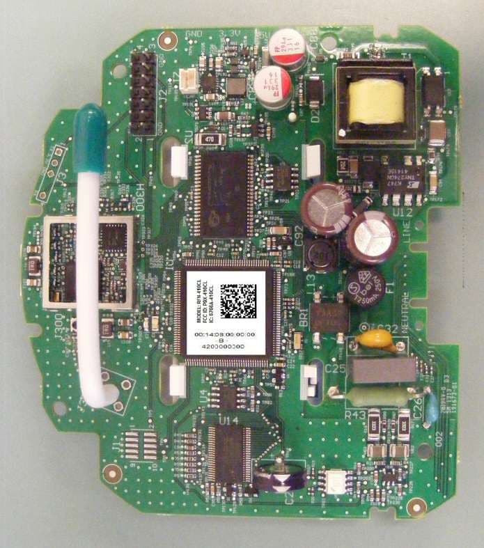
P9X-410CL
Jul 16, 2013RFN-410CL
Equipment Class
DSS - Part 15 Spread Spectrum Transmitter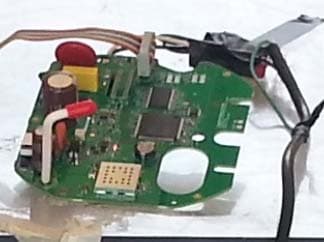
P9X-430SL
Jun 18, 2013RFN-430SL
Equipment Class
DSS - Part 15 Spread Spectrum Transmitter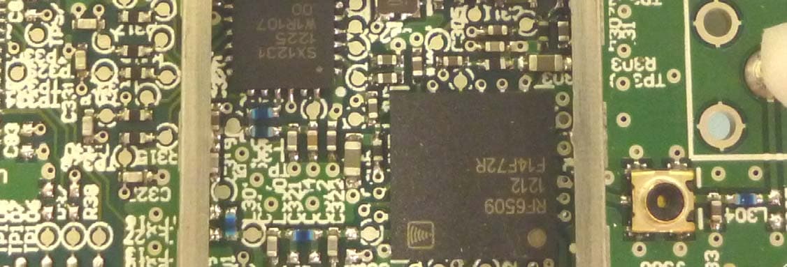
P9X-420CL1WNZ
Jan 09, 2013RFN 420CL(1W, NZ) Module
Equipment Class
DSS - Part 15 Spread Spectrum Transmitter
P9X-420CL1W
Jan 09, 2013Utility Meter Reading Transmitter
Equipment Class
DSS - Part 15 Spread Spectrum Transmitter
P9X-430ELA31W
Nov 25, 2012RFN 430EL-A3 (1W)
Equipment Class
DSS - Part 15 Spread Spectrum Transmitter