PANBT0002MBluetooth module
CC&C Technologies, Inc.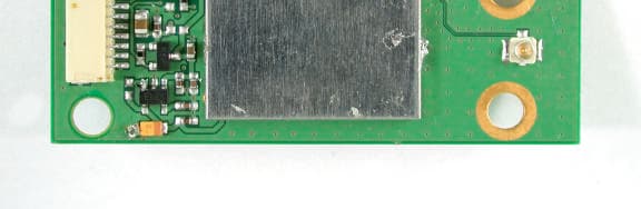
Click to zoom
Application Details
- Equipment Class
- DSS - Part 15 Spread Spectrum Transmitter
- Date of Grant
- Jul 24, 2002
- Application Purpose
- Original Equipment
- Date of Application
- Jul 24, 2002
- Equipment Note
- Bluetooth module
- Frequency Range
- 2402.00000000 - 2480.00000000
- Company
- CC&C Technologies, Inc.
- Country
- Taiwan
Documents & Files
Document Text
Text extracted from the exhibit documents filed with the FCC. Open a document above to read the original.
Users Manual
Bluetooth Module User’s Guide Version 1.0 Federal Communication Commission Interference Statement This equipment has been tested and found to comply with the limits for a Class B digital device, pursuant to Part 15 of the FCC Rules. These limits are designed to provide reasonable protection against harmful interference in a residential installation. This equipment generates, uses and can radiate radio frequency energy and, if not installed and used in accordance with the instructions, may cause harmful interference to radio communications. However, there is no guarantee that interference will not occur in a particular installation. If this equipment does cause harmful interference to radio or television reception, which can be determined by turning the equipment off and on, the user is encouraged to try to correct the interference by one of the following measures: ● Reorient or relocate the receiving antenna. ● Increase the separation between the equipment and receiver. ● Connect the equipment into an outlet on a circuit different from that to which the receiver is connected. ● Consult the dealer or an experienced radio/TV technician for help. FCC Caution: Any changes or modifications not expressly approved by the party responsible for compliance could void the user's authority to operate this equipment. This device complies with Part 15 of the FCC Rules. Operation is subject to the following two conditions: (1) This device may not cause harmful interference, and (2) this device must accept any interference received, including interference that may cause undesired operation. IMPORTANT NOTE: FCC Radiation Exposure Statement: This equipment complies with FCC radiation exposure limits set forth for an uncontrolled environment. This equipment should be installed and operated with minimum distance 20cm between the radiator & your body. This transmitter must not be co-located or operating in conjunction with any other antenna or transmitter. This device is intended only for OEM integrators under the following conditions: 1) The antenna must be installed such that 20 cm is maintained between the antenna and users, and 2) The transmitter module may not be co-located with any other transmitter or antenna. As long as 2 conditions above are met, further transmitter test will not be required. However, the OEM integrator is still responsible for testing their end-product for any additional compliance requirements required with this module installed (for example, digital device emissions, PC peripheral requirements, etc.). IMPORTANT NOTE: In the event that these conditions can not be met (for example certain laptop configurations or co-location with another transmitter), then the FCC authorization is no longer considered valid and the FCC ID can not be used on the final product. In these circumstances, the OEM integrator will be responsible for re- evaluating the end product (including the transmitter) and obtaining a separate FCC authorization. End Product Labeling This transmitter module is authorized only for use in device where the antenna may be installed such that 20cm may be maintained between the antenna and users (for example access points, routers, wireless ADSL modems, and similar equipment). The final end product must be labeled in a visible area with the following: “Contains TX FCC ID: PANBT0002M”. Manual Information That Must be Included The users manual for end users must include the following information in a prominent location “ IMPORTANT NOTE: To comply with FCC RF exposure compliance requirements, the antenna used for this transmitter must be installed to provide a separation distance of at least 20 cm from all persons and must not be co-located or operating in conjunction with any other antenna or transmitter. This is modular approval and only two antennas have been tested with this device. Only those antennas tested in the certification application are authorized. Any other antenna used with the module may require a separate authorization and ID number. Tested to Comply with FCC Standards FOR HOME OR OFFICE USE 1. General Description CC&C BT-0002M Bluetooth module class II is powered by CSR BlueCore2, which with RF and baseband function been integrated in a single chip and was designed for Bluetooth 2.4 GHz wireless applications. With band-pass filter, balun, crystal and flash memory built on, it can reduce external components and provide a hardware engineer with a speed and convenient way to complete their designs. Because of compact sizes, they can easily design into customers’ target devices. For instance, they can be used for PDA, notebook, tablet PC, keyboard and mouse as an internal module. The BT-0002M develops the Bluetooth protocol stacks, profiles and with a plenty of software development and integration experiences, CC&C can help customer to design a specific device. 2. General Specification Model NameBT-0002M Product NameBT Module (CSRBC02)-Class II Size52x19x2.7mm Weight2.8 gram SpecificationBluetooth spec. 1.1 Antenna terminal50 Ohm Power ClassClass-II Digital interfaceBoard to board connector for USB interface or UART interface Operating Voltage3.3V +/- 0.3V ; 5V (USB) Operating CurrentTBD Operating Temp. -10 ~ 70°C 3. Pin assignment 4. General Radio Characteristics TransmitterMinTypMaxUnitRemarks Maximum RF Output Power-203.23dBm RF Power control range25dBm ±140 ±175 kHz11110000modModulation Characteristics ±115 kHz1010mod Initial Carrier Freq accuracy ±25 kHzPRBS9 ±25 kHzDH1 ±20 kHz/50us Drift Rate ±40 kHzDH3 ±20 kHz/50us Drift Rate ±40 kHz Carrier Freq drift DH5 ±20 kHz/50us Drift Rate 20dB bandwidth for modulated carrier |M-N|=2-20dBmIn-band spurious emissions |M-N|>=3 -40dBm ReceiverMinTypMaxUnitRemarks SensitivityDH1, DH3, DH5 --75-dBm C/I CO-Channel TBD11dB C/ I 1MHz TBD0dB C/ I 2MHz TBD-30dB*1 C/ I 2MHz TBD-40dB*1 C/ I Image TBD-9dB Interference Performance C/ I Image TBD-20dB*1 Intermodulation CharacteristicsTBDdBm 30MHz-2000MHz-10dBm 2000-2399MHz-27dBm 249…
Text truncated - open the document above for the full version.
Users Manual
Bluetooth Module User’s Guide Version 1.0 Federal Communication Commission Interference Statement This equipment has been tested and found to comply with the limits for a Class B digital device, pursuant to Part 15 of the FCC Rules. These limits are designed to provide reasonable protection against harmful interference in a residential installation. This equipment generates, uses and can radiate radio frequency energy and, if not installed and used in accordance with the instructions, may cause harmful interference to radio communications. However, there is no guarantee that interference will not occur in a particular installation. If this equipment does cause harmful interference to radio or television reception, which can be determined by turning the equipment off and on, the user is encouraged to try to correct the interference by one of the following measures: ? Reorient or relocate the receiving antenna. ? Increase the separation between the equipment and receiver. ? Connect the equipment into an outlet on a circuit different from that to which the receiver is connected. ? Consult the dealer or an experienced radio/TV technician for help. FCC Caution: To assure continued compliance, (example - use only shielded interface cables when connecting to computer or peripheral devices). Any changes or modifications not expressly approved by the party responsible for compliance could void the user's authority to operate this equipment. This device complies with Part 15 of the FCC Rules. Operation is subject to the following two conditions: (1) This device may not cause harmful interference, and (2) this device must accept any interference received, including interference that may cause undesired operation. IMPORTANT NOTE: FCC Radiation Exposure Statement: This equipment complies with FCC radiation exposure limits set forth for an uncontrolled environment. This equipment should be installed and operated with minimum distance 20cm between the radiator & your body. This transmitter must not be co-located or operating in conjunction with any other antenna or transmitter. End Product Labeling This transmitter module is authorized only for use in device where the antenna may be installed such that 20cm may be maintained between the antenna and users (for example access points, routers, wireless ADSL modems, and similar equipment). The final end product must be labeled in a visible area with the following: “Contains TX FCC ID: PANBT0002M”. Tested to Comply with FCC Standards FOR HOME OR OFFICE USE 1. General Description CC&C BT-0002M Bluetooth module class II is powered by CSR BlueCore2, which with RF and baseband function been integrated in a single chip and was designed for Bluetooth 2.4 GHz wireless applications. With band-pass filter, balun, crystal and flash memory built on, it can reduce external components and provide a hardware engineer with a speed and convenient way to complete their designs. Because of compact sizes, they can easily design into customers’ target devices. For instance, they can be used for PDA, notebook, tablet PC, keyboard and mouse as an internal module. The BT-0002M develops the Bluetooth protocol stacks, profiles and with a plenty of software development and integration experiences, CC&C can help customer to design a specific device. 2. General Specification Model NameBT-0002M Product NameBT Module (CSRBC02)-Class II Size52x19x2.7mm Weight2.8 gram SpecificationBluetooth spec. 1.1 Antenna terminal50 Ohm Power ClassClass-II Digital interfaceBoard to board connector for USB interface or UART interface Operating Voltage3.3V +/- 0.3V ; 5V (USB) Operating CurrentTBD Operating Temp. -10 ~ 70 3. Pin assignment 4. General Radio Characteristics TransmitterMinTypMaxUnitRemarks Maximum RF Output Power-202.55dBm RF Power control range25dBm ±140 ± kHz11110000modModulation Characteristics ± kHz1010mod Initial Carrier Freq accuracy ± kHzPRBS9 ± kHzDH1 ± kHz/50usDrift Rate ± kHzDH3 ± kHz/50usDrift Rate ± kHz Carrier Freq drift DH5 ± kHz/50usDrift Rate 20dB bandwidth for modulated carrier |M-N|=2-20dBmIn-band spurious emissions |M-N| -40dBm ReceiverMinTypMaxUnitRemarks SensitivityDH1, DH3, DH5 --75-dBm C/I CO-Channel TBD11dB C/ I 1MHz TBD0dB C/ I 2MHz TBD-30dB*1 C/ I 2MHz TBD-40dB*1 C/ I Image TBD-9dB Interference Performance C/ I Image TBD-20dB*1 Intermodulation CharacteristicsTBDdBm 30MHz-2000MHz-10dBm 2000-2399MHz-27dBm 2498-3000MHz-27dBm Out-of-band Blocking 3GHz-12.75GHz-10dBm 5. BlueCore 2-External Data 1) Device Features ¦ Low power 1.8V operation ¦ Small footprint in 96-Ball VFBGA Package (6x6mm) ¦ Fully qualified Bluetooth component ¦ 0.18μm CMOS technology ¦ Full speed class 2 Bluetooth operation with full 7 slave piconet support ¦ Support for 8Mbit external Flash ¦ Minimum external components ¦ Operates over full industrial temperature range ( -40 T 105C) 2) General Description BlueCore2-External is a single chip radio and baseband IC for Bluetooth 2.4GHz radios implemented in CMOS technology. When used with external ROM containing the CSR Bluetooth software stack, it provides a fully compliant Bluetooth system for data and voice communications. 3) Applications The design is optimised to require few external RF components to facilitate rapid design of the application printed circuit board and therefore the fastest possible time to market and lowest overall cost. Included in the device are auto-calibration and built-in-self-test (BIST) routines to simplify development, type approval and production test. All hardware and device firmware is fully compliant with the Bluetooth specification. ¦ PC Notebooks ¦ Cellular Handsets ¦ Cordless Headsets ¦ Personal Digital Assistants (PDAs) ¦ Computer Accessories (Compact Flash, PCMCIA and SD cards) 4) Description of Functional Blocks Radio Transceiver and Synthesiser The receiver features a near-zero IF architecture that allows the channel filters to be integrated on to the die. Sufficient out-of-band blocking specification at the LNA in…
Text truncated - open the document above for the full version.
Cover Letter(s)
8F, 150, Jian Yi Road, Chung Ho City, Taipei County, Taiwan 235, R.O.C. TEL: 886-2-8226-5088 FAX: 886-2-8226-5077 E-mail: [email protected] Inform Letter Dear Customer, According to FCC’s regulation, the following Declaration of Conformity has to be made by a company located in USA. They are: This device has been confirmed to be in compliance with the requirements of ANSI C63.4 & FCC part 15 regulations. The test result has been shown in the ADT test report with number RF910614R01. And this compliance is subject to the following two conditions: (1) This device may not cause harmful interference and, (2) This device must accept any interference received, including interference that may cause undesired operation. This declaration can be a separate sheet and be sure that the following message will be also included in this declaration: 1) Product name, model name and trade name. 2) Company name, and address of the one who is responsible for this declaration. 3) Name, title, telephone and fax number as well as the signature of the contact person. Thanks for your attention. Technologies, Inc.
Cover Letter(s)
American Telecommunications Certification Body Inc. 6731 Whittier Ave, McLean, VA 22101 July 10, 2002 RE: FCC ID: PANBT0002 Attention: Alan Lane I have a few comments on this Application. 1 The FCC ID label and label location size appear to be large enough to place the ID number and the statement required in 15.19 (2-condition statement). Please provide a sample label with the required ID and statement, or please provide justification under 2.925 as to why the statement of 15.19 is not on the product. xx 2 Channel separation and bandwidth were measured in data mode. However, Bluetooth devices also have an acquisition mode. What is the measured bandwidth and channel separation in this mode? xx 3 Not only must conducted band edge emissions be –20dB below the highest emission level of operating band, they must also meet the restricted band requirements of 15.209 at 3 meters. The spurious emissions tables give no indication that the restricted bands between 2310-2390 GHz and 2483.5-2500 GHz were investigated. Please provide evidence that these two restricted bands were investigated on the OATS 3 meter range and that they are in compliance to 15.205 limits. xx 4 Since this is a limited modular approval and since only two antennas have been tested with this device, the manual needs to state that only those antennas tested in the certification application are authorized. Any other antenna used with the module may require a separate authorization and ID number. xx 5 The report states several model numbers for which the test report applies, but doe not provide information on the differences between these model numbers. Please provide a short description between the model tested and the other model numbers. xx 6 The manual states that this device can be used in a portable Cellular Handsets, Cordless headsets and Personal Digital Assistants (PDAs). While the device power certainly appears low enough to use in portable devices, the report and application for this device specifically states it is for mobile device use only. Please correct the manual to reflect the conditions of modular approval. If the device is to be used in portable devices, please retest the transmitter using the antennae that will be allowed to be used with this module in a portable configuration. xx 7 The manual gives a range of power between –2 and +2.5dBm. Please note that the maximum power on any grant is the maximum power measured at the time of testing, not the power specified in the technical documentation or manual. In this case the maximum power is 0.95mW or –0.22dBm. Since power levels cannot be changed by a PC2, this means that any device exceeding this maximum (-0.22dBm) must apply for a separate ID. If the manufacturer wishes to market this device at the +2.5dBm level, then testing must be done at this higher level. Please provide test data showing compliance at the higher power level mentioned in the manual, or please correct the manual to reflect the tested power level. xx Dennis Ward mailto:[email protected] The items indicated above must be submitted before processing can continue on the above referenced application. Failure to provide the requested information may result in application termination. Correspondence should be considered part of the permanent submission and may be viewed from the Internet after a Grant of Equipment Authorization is issued. l Page 2July 10, 2002 Please do not respond to this correspondence using the email reply button. In order for your response to be processed expeditiously, you must submit your documents through the AmericanTCB.com website. Also, please note that partial responses increase processing time and should not be submitted. Any questions about the content of this correspondence should be directed to the sender.
Cover Letter(s)
Subject: PANBT0002M request for information Date: Wed, 24 Jul 2002 16:30:46 +0800 From: [email protected] To: [email protected] Dear Dennis, For item 1, the label is too small to put the statement on (2.4cm*1.4cm). So the statement is placed in the user's manual. For other items, please see revised files which has been uploaded on your website. Regards, Rennie T ----- Âà§eªÌ Alan Lane/ADT ©ó 2002/07/11 09:14 AM ----- Dennis Ward <dennis@yosemi ¦¬¥ó¤H¡G Alan Lane <[email protected]> te.net> °Æ¥»§Û°e¡G ¥D¦®¡G PANBT0002M request for information 2002/07/11 04:16 AM Hi Alan Attached is a request for information on the modular device ID above Thanks Dennis [email protected] (See attached file: 7-10-02 PANBT0002M request for information.PDF) --------------------------------------------------------------------- Name: 7-10-02 PANBT0002M request for 7-10-02 PANBT0002M request for information.PDF information.PDF Type: Acrobat (application/pdf) Encoding: base64
Cover Letter(s)
Response to Correspondence Reference Number 4963 Dear Joe This is in response to your request for information on - FCC ID: PANBT0002M Applicant: CC&C Technologies, Inc. Correspondence Reference Number: 4963 731 Confirmation Number: TC428870 Date of Original Email: 08/23/2002 Each subject is answered immediately after your question. Subject: 1) The filing does not contain the reply to the TCB requested information. Please submit the grantee reply after you are satisfied with their reply. In particular, interest is the classification of whether or not this is a mobile or portable device and the correction of the manual, grant condition and RF safety exhibit accordingly. The answer from the applicant was provided as a pdf file “Response to ATCB request.pdf”. This basically stated that item one (label size) was too small, and that all other items were answered in the revised files. I have created another pdf file from an email sent stating that retesting was being done as an answer to items 2-5 and 7. Since re-testing was being performed, it was not necessary to provide both the old and new report. However, since the FCC has requested how the client answered ATCB questions and why the limited modular approval was given, I have provided the original report, the original manual and the original MPE calculations to the FCC server. As to why the classification of limited modular approval -- The MPE statement provided shows the calculations using the new report information. While the distance for safe MPE calculates to about 1/2cm, the MPE report and manual recommends 20cm separation. While the device appears to be capable of portable use, the test lab recommend this 20cm ‘safe’ distance and did not change the classification as mentioned in the request for information, also, the manufacturer states in the manual “... IMPORTANT NOTE: To comply with FCC RF exposure compliance requirements, the antenna used for this transmitter must be installed to provide a separation distance of at least 20 cm from all persons and must not be co- located or operating in conjunction with any other antenna or transmitter.” Because of these, I placed this limit on the module to require that the intent of the manufacturer be met. 2) Please explain why the authorizations is for a limited modular approval. What is the authorization limited to? In addition to the above, the limited modular approval limits the device to only those antennae tested with the device and to a minimum of 20cm between device and antenna (i.e. mobile and not portable). On page 3 of the revised manual, it states: End Product Labeling This transmitter module is authorized only for use in device where the antenna may be installed such that 20cm may be maintained between the antenna and users (for example access points, routers, wireless ADSL modems, and similar equipment). And: Manual Information That Must be Included: (page 3) ... IMPORTANT NOTE: To comply with FCC RF exposure compliance requirements, the antenna used for this transmitter must be installed to provide a separation distance of at least 20 cm from all persons and must not be co-located or operating in conjunction with any other antenna or transmitter. This is modular approval and only two antennas have been tested with this device. Only those antennas tested in the certification application are authorized. Any other antenna used with the module may require a separate authorization and ID number. Hopefully this has answered your concerns about the grant. If the FCC desires to remove the limitations and grant the device for use in portable hosts please let me know. Thanks for your assistance in this matter Dennis Ward [email protected]
Cover Letter(s)
Subject: [Fwd: PANBT0002M request for information] Date: Wed, 17 Jul 2002 09:23:35 +0800 From: [email protected] To: [email protected] CC: [email protected], [email protected] Dear Dannis This project needs to be re-tested, we'll submit it to you as soon as the report is ready. Thanks. Regards Emily ----- Âà§eªÌ Emily Lu/ADT ©ó 2002/07/17 09:21 AM ----- Dennis Ward <dennis@yosemi ¦¬¥ó¤H¡G [email protected], te.net> [email protected] °Æ¥»§Û°e¡G 2002/07/17 ¥D¦®¡G [Fwd: PANBT0002M request for information] 08:07 AM Hi Emily the attached email is over a week old. I have not heard back from Alan so I assume he is out of the office. I have therefore sent this forward to you. Please let me know if there is anything you can do with this application information request or if it requires ALan's attention. thanks Dennis Ward [email protected]
External Photos
Page 1 ANNEX PHOTOGRAPHS OF EUT Page 2
ID Label/Location Info
FCC ID : PANBT0002M MAC: 000272000000 Made In Taiwan Bluetooth Module 24mm 14 mm The label sticks on Bluetooth Module board.
Internal Photos
Page 3 Page 4 Page 5 Page 6 Page 7
Operational Description
FCC ID: PANBT0002M ADT No.910614R01 Operational Description The transmitter of the EUT is seeking for Module Approval specific to the host equipment such as Notebook. The antenna types are Inverted F antenna and Printed Dipole antenna. The antenna connector is UFL. Under normal use condition, the user has to keep at least 20cm separation distance between radiator and the body of the user. The other instruction, please have a look at the users manual. This device is a Frequency Hopping device with 79 hopping frequencies.
RF Exposure Info
FCC ID: PANBT0002M ADT No.: 910614R01 FCC TEST REPORT REPORT NO.: RF910614R01 MODEL NO.: BT-0002M BT-0002 BT-0002MS BT-0002A BT-0002B ACCORDING: FCC Guidelines for Human Exposure IEEE C95.1 APPLICANT:CC&C TECHNOLOGIES INC. ADDRESS: 8F, 150, Jian Yi Road, Chung Ho City, Taipei, Taiwan, R.O.C. ISSUED BY:Advance Data Technology Corporation LAB LOCATION:47 14th Lin, Chiapau Tsun, Linko, Taipei, Taiwan, R.O.C. 0528 ILAC MRA Lab Code: 200102-0 FCC ID: PANBT0002M ADT No.: 910614R01 RF Exposure Measurement (Portable Device) 1. Introduction 2.4GHz frequency band is regarded specially as a dangerous band for its heating harmfulness to the human body. That’s why microwave oven is operating in this frequency band. The manufacturer whose product is working in this frequency band is obligatory to prove the harmfulness of his product. In this document, we try to prove the safety of radiation harmfulness to the human body for our product. The limit for Maximum Permissible Exposure (MPE) specified in FCC 1.1310 is followed. The Gain of the antenna used in this product is measured in a Fully Anechoic Chamber (FAC), and the maximum total power input to the antenna is measured. Through the Friis transmission formula and the maximum gain of the antenna, we can calculate the distance, away from the product, where the limit of MPE is reached. 2. RF Exposure Limit According to FCC 1.1310: The criteria listed in the following table shall be used to evaluate the environmental impact of human exposure to radio-frequency (RF) radiation as specified in 1.1307(b). FCC ID: PANBT0002M ADT No.: 910614R01 LIMITS FOR MAXIMUM PERMISSIBLE EXPOSURE (MPE) Frequency Range (MHz) Electric Field Strength (V/m) Magnetic Field Strength (A/m) Power Density (mW/cm 2 ) Average Time (minutes) (A)Limits For Occupational / Control Exposures 30-30061.40.1631.06 300-1500......F/3006 1500-100,000......56 (B)Limits For General Population / Uncontrolled Exposure 30-30027.50.0730.230 300-1500......F/150030 1500-100,000......1.030 F = Frequency in MHz 3. Friis Formula Friis transmission formula : Pd = (Pout*G) / (4*pi*r 2 ) where Pd = power density in mW/cm 2 Pout = output power to antenna in mW G = gain of antenna in linear scale Pi = 3.1416 R = distance between observation point and center of the radiator in cm Pd is the limit of MPE, 1 mW/cm 2 . If we know the maximum Gain of the antenna and the total power input to the antenna, through the calculation, we will know the distance r where the MPE limit is reached. Ref. : David K. Cheng, Field and Wave Electromagnetics, Second Edition, Page 640, Eq. (11-133). 4. EUT Operating condition The software provided by Manufacturer enabled the EUT to transmit and receive data at lowest, middle and highest channel individually. FCC ID: PANBT0002M ADT No.: 910614R01 5. Test Results 5.1 Antenna Gain The maximum Gain measured in Fully Anechoic Chamber is -2dBi or 0.63 (numeric). 5.2 Output Power Into Antenna & RF Exposure Distance : CHANNEL CHANNEL FREQUENCY (MHz) OUTPUT POWER TO ANTENNA (mW) MINIMUM ALLOWABLE DISTANCE ( r ) FROM SKIN (Centi-Meter) 024021.690.29 3924411.990.32 78 2480 2.10 0.33 The minimum allowable distance is very close to the enclosure of the antenna. So, the user has no need to worry about the harmfulness of radiation. But it is recommended to always keep, at least, 20cm separation distance with the antenna.
RF Exposure Info
FCC ID: PANBT0002M ADT No.: 910614R01 FCC TEST REPORT REPORT NO.: RF910614R01 MODEL NO.: BT-0002M BT-0002 BT-0002MS BT-0002A BT-0002B ACCORDING: FCC Guidelines for Human Exposure IEEE C95.1 APPLICANT:CC&C TECHNOLOGIES INC. ADDRESS: 8F, 150, Jian Yi Road, Chung Ho City, Taipei, Taiwan, R.O.C. ISSUED BY:Advance Data Technology Corporation LAB LOCATION:47 14th Lin, Chiapau Tsun, Linko, Taipei, Taiwan, R.O.C. 0528 ILAC MRA Lab Code: 200102-0 FCC ID: PANBT0002M ADT No.: 910614R01 RF Exposure Measurement (Mobile Device) 1. Introduction 2.4 GHz frequency band is regarded specially as a dangerous band for its heating harmfulness to the human body. That’s why microwave oven is operating in this frequency band. The manufacturer whose product is working in this frequency band is obligatory to prove the harmfulness of his product. In this document, we try to prove the safety of radiation harmfulness to the human body for our product. The limit for Maximum Permissible Exposure (MPE) specified in FCC 1.1310 is followed. The Gain of the antenna used in this product is measured in a Fully Anechoic Chamber (FAC), and the maximum total power input to the antenna is measured. Through the Friis transmission formula and the maximum gain of the antenna, we can calculate the distance, away from the product, where the limit of MPE is reached. 2. RF Exposure Limit According to FCC 1.1310: The criteria listed in the following table shall be used to evaluate the environmental impact of human exposure to radio-frequency (RF) radiation as specified in 1.1307(b). FCC ID: PANBT0002M ADT No.: 910614R01 LIMITS FOR MAXIMUM PERMISSIBLE EXPOSURE (MPE) Frequency Range (MHz) Electric Field Strength (V/m) Magnetic Field Strength (A/m) Power Density (mW/cm 2 ) Average Time (minutes) (A)Limits For Occupational / Control Exposures 30-30061.40.1631.06 300-1500......F/3006 1500-100,000......56 (B)Limits For General Population / Uncontrolled Exposure 30-30027.50.0730.230 300-1500......F/150030 1500-100,000......1.030 F = Frequency in MHz 3. Friis Formula Friis transmission formula : Pd = (Pout*G) / (4*pi*r 2 ) where Pd = power density in mW/cm 2 Pout = output power to antenna in mW G = gain of antenna in linear scale Pi = 3.1416 R = distance between observation point and center of the radiator in cm Pd is the limit of MPE, 1 mW/cm 2 . If we know the maximum Gain of the antenna and the total power input to the antenna, through the calculation, we will know the distance r where the MPE limit is reached. Ref. : David K. Cheng, Field and Wave Electromagnetics, Second Edition, Page 640, Eq. (11-133). 4. EUT Operating condition The software provided by Manufacturer enabled the EUT to transmit and receive data at lowest, middle and highest channel individually. FCC ID: PANBT0002M ADT No.: 910614R01 5. Test Results 5.1 Antenna Gain The maximum Gain measured in Fully Anechoic Chamber is -2 dBi or 0.63 (numeric). 5.2 Output Power Into Antenna & RF Exposure Distance : CHANNEL CHANNEL FREQUENCY (MHz) OUTPUT POWER TO ANTENNA (mW) MINIMUM ALLOWABLE DISTANCE ( r ) FROM SKIN (Centi-Meter) 024020.950.22 3924410.820.20 7824800.900.21 The minimum allowable distance is very close to the enclosure of the antenna. So, the user has no need to worry about the harmfulness of radiation. But it is recommended to always keep, at least, 20cm separation distance with the antenna.
Test Report
FCC ID: PANBT0002M Report No.: RF910614R011Issued: June 25, 2002 FCC TEST REPORT REPORT NO.: RF…
Text truncated - open the document above for the full version.
Contact Information
Applicant
Cooper Hou(Product Manager)
Technical Contact
Advance Data Technology CorporationAlan Lane
[email protected]+886-3-327-0910
13-1, Lane19, WenShan 3rd ., St., · Taoyuan · Taiwan
Non-Technical Contact
Advance Data Technology CorporationAlan Lane
[email protected]+886-3-327-0910
Test Firm
Bureau Veritas CPS (H.K.) Ltd. Taoyuan BranchRichard Chen
Technical Specifications
| # | Rule Parts | Frequency Range | Power Output |
|---|---|---|---|
| 1 | 15C | 2.40 GHz - 2.48 GHz | 2.10 mW |
Other Applications from CC&C Technologies, Inc.
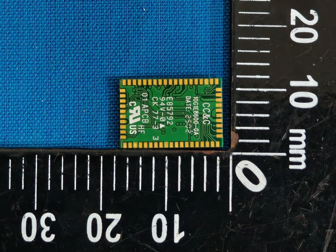
PANBM3095
Jun 24, 2026Bluetooth v5.4 APTX LE Audio RX Module
Equipment Class
DSS - Part 15 Spread Spectrum Transmitter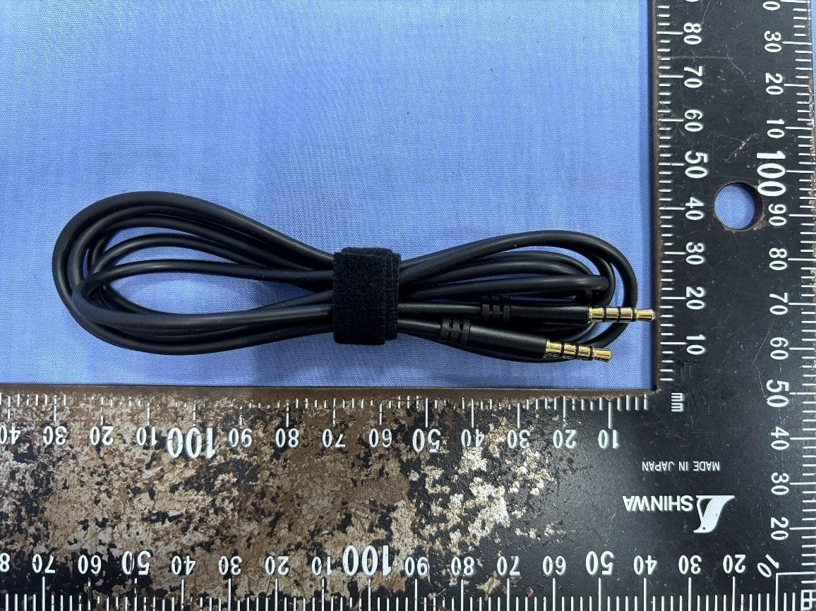
PANBA550T
Sep 26, 2024Triple source to BT5.3 LE Audio Transmitter
Equipment Class
DSS - Part 15 Spread Spectrum Transmitter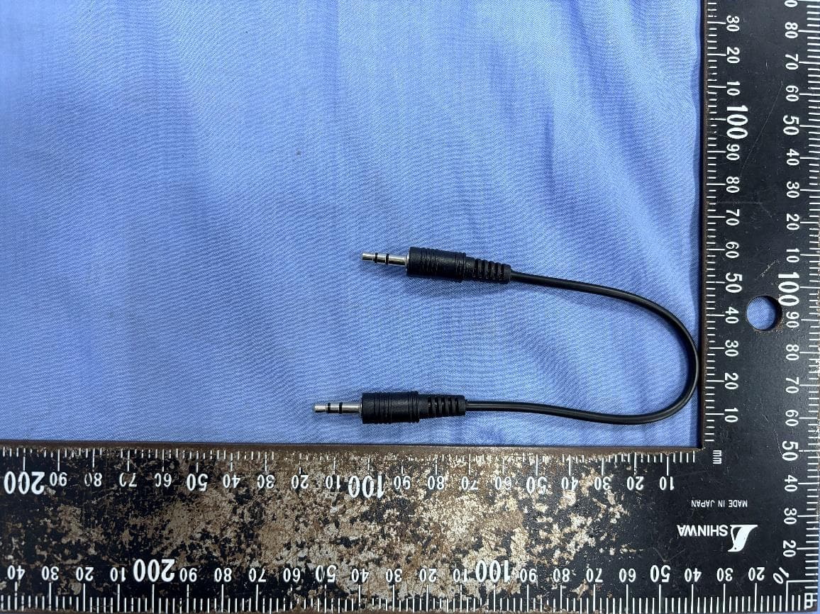
PANBA55T
Sep 26, 2024Dual source to BT5.3 LE Audio Transmitter
Equipment Class
DTS - Digital Transmission System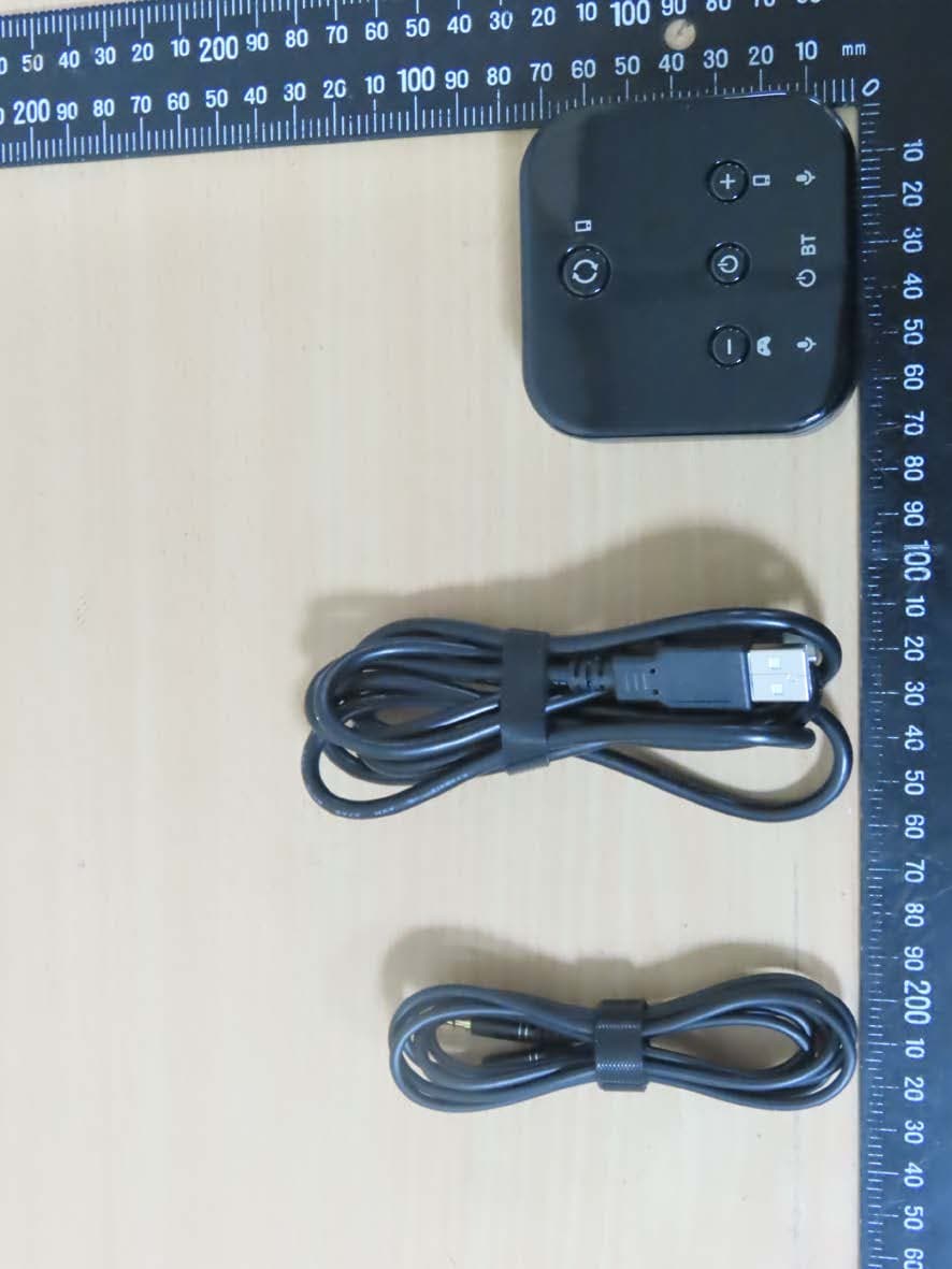
PANBA300M
Dec 08, 2022BT5 Aptx Audio Mixer
Equipment Class
DTS - Digital Transmission System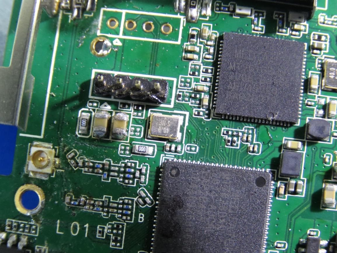
PANWA9563
Dec 17, 2020AC1200 FE Repeater
Equipment Class
NII - Unlicensed National Information Infrastructure TX