PANBT0002M1Bluetooth Module
CC&C Technologies, Inc.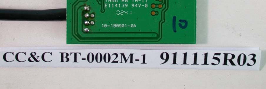
Click to zoom
Application Details
- Equipment Class
- DSS - Part 15 Spread Spectrum Transmitter
- Date of Grant
- Dec 09, 2002
- Application Purpose
- Original Equipment
- Date of Application
- Dec 09, 2002
- Equipment Note
- Bluetooth Module
- Frequency Range
- 2402.00000000 - 2480.00000000
- Company
- CC&C Technologies, Inc.
- Country
- Taiwan
Documents & Files
Document Text
Text extracted from the exhibit documents filed with the FCC. Open a document above to read the original.
Users Manual
Bluetooth Module BT-0002M-1 User’s Guide Version 1.1 Technologies, Inc. 8F, No. 150, Jian Yi Road, Chung Ho City, Taipei County, Taiwan 235, R.O.C. Tel: 886-2-8226-5088 Fax: 886-2-8226-5077 http://www.ccandc.com.tw E-mail: [email protected] Confidential 2 Technologies, Inc. BT-0002M-1 Bluetooth Module Federal Communication Commission Interference Statement This equipment has been tested and found to comply with the limits for a Class B digital device, pursuant to Part 15 of the FCC Rules. These limits are designed to provide reasonable protection against harmful interference in a residential installation. This equipment generates, uses and can radiate radio frequency energy and, if not installed and used in accordance with the instructions, may cause harmful interference to radio communications. However, there is no guarantee that interference will not occur in a particular installation. If this equipment does cause harmful interference to radio or television reception, which can be determined by turning the equipment off and on, the user is encouraged to try to correct the interference by one of the following measures: ● Reorient or relocate the receiving antenna. ● Increase the separation between the equipment and receiver. ● Connect the equipment into an outlet on a circuit different from that to which the receiver is connected. ● Consult the dealer or an experienced radio/TV technician for help. FCC Caution: Any changes or modifications not expressly approved by the party responsible for compliance could void the user's authority to operate this equipment. This device complies with Part 15 of the FCC Rules. Operation is subject to the following two conditions: (1) This device may not cause harmful interference, and (2) this device must accept any interference received, including interference that may cause undesired operation. IMPORTANT NOTE: FCC Radiation Exposure Statement: This equipment complies with FCC radiation exposure limits set forth for an uncontrolled environment. This transmitter must not be co-located or operating in conjunction with any other antenna or transmitter. Confidential 3 Technologies, Inc. BT-0002M-1 Bluetooth Module This device is intended only for OEM integrators under the following conditions: 1) The transmitter module may not be co-located with any other transmitter or antenna. As long as condition above are met, further transmitter test will not be required. However, the OEM integrator is still responsible for testing their end-product for any additional compliance requirements required with this module installed (for example, digital device emissions, PC peripheral requirements, etc.). IMPORTANT NOTE: In the event that these conditions can not be met (for example certain laptop configurations or co-location with another transmitter), then the FCC authorization is no longer considered valid and the FCC ID can not be used on the final product. In these circumstances, the OEM integrator will be responsible for re-evaluating the end product (including the transmitter) and obtaining a separate FCC authorization. End Product Labeling The final end product must be labeled in a visible area with the following: “Contains TX FCC ID: PANBT0002M1”. Manual Information That Must be Included The users manual for OEM integrators must include the following information in a prominent location “ IMPORTANT NOTE: To comply with FCC RF exposure compliance requirements, the antenna used not be co-located or operating in conjunction with any other antenna or transmitter. Confidential 4 Technologies, Inc. BT-0002M-1 Bluetooth Module Description CC&C Technologies, Inc. provides various Bluetooth products. They are suitable for customers to exploit them to implement Bluetooth functionality into various electronic devices. The features of Bluetooth module list as below: Features Model NameBT-0002M-1 StandardBluetooth v1.1 Frequency Band2.4~2.4835GHz unlicensed ISM band Spread SpectrumFHSS (Frequency Hopping Spread Spectrum) RF Output PowerClass 2 (under 4 dBm) Antenna terminal50 Ohm DC power3.3V I/O Interface USB Compliant USB V1.1 UART Baud rate up to 921K PCM Yes PIO 12 PIO Dimension15 x 23 mm Photos BT-0002M- 1 Confidential 5 Technologies, Inc. BT-0002M-1 Bluetooth Module Electrical Characteristics Absolute Maximum Ratings Model NameBT-0002M-1Unit Supply VoltageMax. 3.5VV Typ. 3.3VV Min 2.8VV Storage TemperatureMax. 85 o c Min. -40 o c Recommend Operation Conditions Model NameBT-0002M-1Unit Supply VoltageMax. 3.5VV Typ. 3.3VV Min 2.8VV Operation Temperature Max. 70 o c Min. 0 o c Input/Output Terminal Characteristics Model NameBT-0002M-1Unit Digital (UART, PIO) V IL – Max +0.8V Min -0.4V V IH – Max 3.7V Min 2.31V USB V IL – Max 0.99V Min -V V IH – Max -V Min 2.31V V OL – Max 0.2V Min 0V V OH – Max 3.3V Min 2.8V Confidential 6 Technologies, Inc. BT-0002M-1 Bluetooth Module Electrical Characteristics - Continue Current Consumption Model NameBT-0002M-1Unit Mode -Active ACL data transfer 115.2 Kbps UART (Master)30mAmA ACL data transfer 720 Kbps USB (Master)75mAmA ACL data transfer 720 Kbps USB (Slave)75mAmA SCO connection HV3 (Master)TBAmA SCO connection HV3 (Slave)TBAmA SCO connection HV1 (Master)TBAmA SCO connection HV1 (Slave)TBAmA Mode -Idle UART interface2mAmA USB interface6mAmA Confidential 7 Technologies, Inc. BT-0002M-1 Bluetooth Module Radio Characteristics -Transmission Transmission ItemMeasureBluetooth Spec.Note Output Power 3dBm 2400.94>2400MHz Frequency Range 2481.06<2483.5MHz Measuring the –30dBm point when use channel 0 and 79 2402 MHz 800k<1MHz 2441 MHz 800k<1MHz 20 dB Bandwidth 2480 MHz 800k<1MHz |M-N|=2 -25dBm ≤ -20dBm Transmit Output Spectrum Adjacent Channel Power |M-N|≥3 -45dBm ≤ -40dBm . Modulation Characteristics ∆F1 max 00001111 payload ∆F1 avg 167k 140 ≤ ∆F1 avg ≤ 175KHz ∆F2 max 195k ≥ 115KHz at least 99.9%01010101 payload ∆F2 avg ∆F2 avg /∆F1 avg 1.04≥ 0.8 2402 MHz 6.24k± 75KHz 2441 MHz 6.4k± 75KHz Initial Carrier Frequency Tolerance 2480 MHz 2.66k± …
Text truncated - open the document above for the full version.
Cover Letter(s)
American Telecommunications Certification Body Inc. 6731 Whittier Ave, McLean, VA 22101 December 9, 2002 RE: FCC ID: PANBT0002M1 Attention: Vivi Wang I have a few comments on this Application. 1 Please note that a module is designed to fit inside a host device while this device appears to connect to the USB port of another device. As such it would appear to be a USB dongle transmitter. Please explain how this is appropriate for a modular approval as tested. 2 Your documentation is not clear. In one set of documents you classify this as a module meeting all the requirements of a module. Yet in other documents you classify this as a Limited Modular Approval (see “Cover Letter - Modular Approval request_PANBT0002M1.pdf’). Please note, LMA and modular approval are two different approvals with different requirements. Please understand that Limited Modular Approvals are devices that are tested in a particular host and are ONLY able to be used in that very specific host. They are typically “Limited” Modular Approvals because they do not meet one or more of the modular approval requirements. LMA’s then cannot be used in generic type devices such as ‘notebooks’, etc. Use in any other host requires a PC2 or new ID. You have stated that the device is for use in PDAs Notebooks, etc. Yet have not specifically stated the exact host in a Limited Modular Approval. Should this be granted as an LMA, please understand that ONLY THE HOST TESTED will be approved for this device. However, as a modular approval the device could then fit into generic notebooks etc, depending on the power. Please correct your documentation to state the type approval being sought – i.e. Modular – not Limited Modular. 3 In the external photos you show three antenna types. Two are soldered antenna(s) while the other is a PCB antenna on the board. However, since an intentional radiator cannot transmit from two antenna(s) at the same time you will need to verify that the lead to the onboard antenna is cut and made inactive when one of the other antenna(s) are soldered to the antenna point. Please provide evidence that the onboard antenna is not functional when either of the other two antenna(s) is soldered onto the board. 4 There appears to be other I/O capabilities than the USB. What steps have you taken to insure that the USB is the worse case I/O configuration and that the other configurations do not cause the transmitter to go out of compliance? 5 You must show compliance for radiated spurious emissions for all three antenna(s). The data provided is not clear as to what antenna goes with what data. Please provide data showing all three proposed antenna(s) have been tested for radiated spurious emissions. 6 Please note that the photos of the device in the internal and external photos do not appear to be the same device as shown in the photo in the manual (see page 4 of 10 in the manual). Please explain and correct the manual to reflect the same device as in the internal photos provided and as the device tested. Dennis Ward mailto:[email protected] The items indicated above must be submitted before processing can continue on the above referenced application. Failure to provide the requested information may result in application termination. Correspondence should be considered part of the permanent submission and may be viewed from the Internet after a Grant of Equipment Authorization is issued. z Page 2 December 9, 2002 Please do not respond to this correspondence using the email reply button. In order for your response to be processed expeditiously, you must submit your documents through the AmericanTCB.com website. Also, please note that partial responses increase processing time and should not be submitted. Any questions about the content of this correspondence should be directed to the sender.
Cover Letter(s)
Here is my reply to your questions: 1) No, the cable with USB head shown in the external photo is only for "stand-alone" test configuration. This cable will not be used while this module has been integrated into the host. The I/O port on the PCB will be soldered and fixed with the I/O of the host equipment. By the way, when this module is used to be with the notebook, it will be integrated inside the notebook. 2) Yes, indeed. But I hope you can understand the LMA we follow recently is not exactly the same as that described in FCC public notice. In FCC public notice, you need to test the module under the integration configuration. Of course, if you think module approval is strongly recommended, I will revise the request letter. 3) 3 types of antennas could be "selected" in this application. But in one host application, only one antenna will be used. In other words, only one antenna port is designed in this module, there is no diversity function. While the soldered antenna is used, the pin of the RF output function will not be connected with the printed antenna. It is very difficult for us to show you the evidence, but no one will be so stupid to connect both printed and soldered antenna on the same pin, because the impedance mismatch will make the communication quality very poor. 4) As I mentioned in above (1), the I/O port is just an I/O port, it is not specific to USB. For the module, such I/O port is only some pins. While it is integrated into the host device, only short wires maybe will be used to connect with the host. 5) Turn to section 3.2. There is description of the test modes. 3 kind of antenna has been tested completely. 6) We will revise the manual very soon. Thank you. Alan
Cover Letter(s)
Subject: ¦^«H¡G [Fwd: audit] Date: Mon, 20 Jan 2003 20:15:19 +0800 From: [email protected] To: [email protected] Dennis, 1. No, the interface is not designed specially for USB only. The USB here in our testing is for testing only, we need to control this module for testing. This module is going to be integrate into the host end proudct, It is not for external plug-in. 2. This module is a BlueTooth module. Basically it is for data transmission. But if it is used in device such as hands free kit, and the voice signal can be digitalized before feeding to this module, then voice signal could be transmitted. 3. Yes. 4. & 5. The circuit photo shown in the users manual is covered in the metal shielding shown in the external photo exhibition. Regarding to the circuit board shown in the exhibition, I think I should say that is what this module need. This BlueTooth has been well defined, it is similar like an IC with well defined pins. Except one pin connected with printed antenna, others is for base band data and DC voltage. There is no feedback path between this module and host device which is for output power control. Best Regards, Dr. Alan Lane Tel: +886 3 3270910 Fax: +886 3 3270892 Dennis Ward <dennis@yosemi ¦¬¥ó¤H¡G Alan Lane ADT <alan [email protected]>, te.net> <[email protected]>, Emily - ADT <emily [email protected] °Æ¥»§Û°e¡G Bill Graff - ATCB <[email protected]> 2003/01/20 ¥D¦®¡G [Fwd: audit] 10:16 AM How are the answers to the FCC correspondence questions coming. You will need to respond soon. See attached email reminder thanks Dennis ----- °T®§ ̈Ó¦Û [email protected] (¦ì©ó Thu, 9 Jan 2003 12:27:13 -0500 (EST)) ----- ±H¥ó¤H: [email protected] ¥D¦®: audit To: William Graff From: Tim Harrington [email protected] FCC Equipment Authorization Branch Re: FCC ID: PANBT0002M1 Applicant: CC&C Technologies, Inc. Correspondence Reference Number: 6472 731 Confirmation Number: TC592294 Date of Original Email: 01/09/2003 Subject: audit 1) Aren't USB connectors usually for external plug-in? 2) Is device intended/allowed for use in PDAs that have built-in phone function? 3) User manual footer says confidential - for OEM use installation instructions should be confidential, but end-user may still need non-confidential operating instructions. 4) User manual pg 4 photo does not appear to match internal or external photo exhibits - please clarify and/or revise. 5) User manual pg 9 shows pinout - please verify that device will only be marketed in circuit board as shown in photo exhibits. The items indicated above must be submitted before processing can continue on the above referenced application. Failure to provide the requested information within 30 days of the original e-mail date may result in application dismissal pursuant to Section 2.917(c). DO NOT Reply to this email by using the Reply button. In order for your response to be processed expeditiously, you must upload your response via the Internet at www.fcc.gov, E-Filing, OET TCB Electronic Filing, TCB Login. If the response is submitted through Add Attachments, a message which informs the processing staff that a new exhibit has been submitted must also be submitted via Submit Correspondence. Also, please note that partial responses increase processing time and should not be submitted. Any questions about the content of this correspondence should be directed to the e-mail address listed below the name of the sender.
External Photos
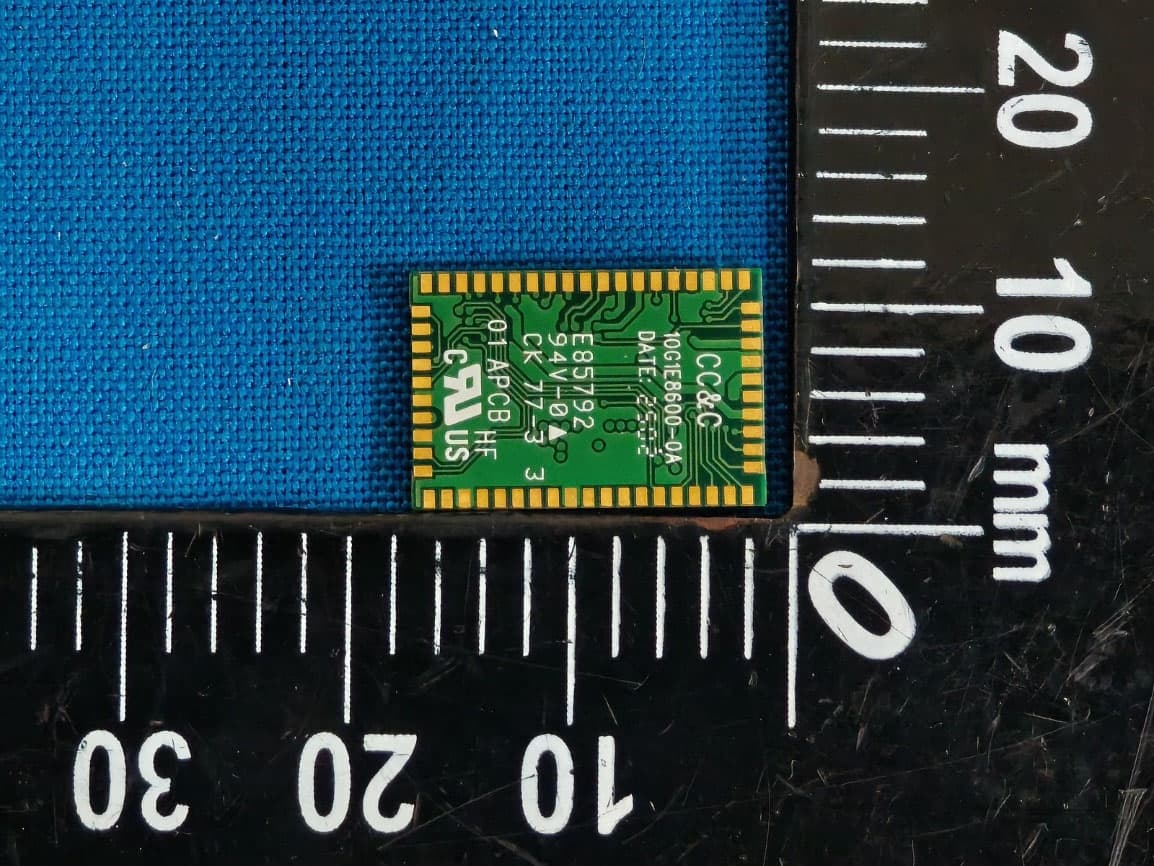
Page 1 ANNEX PHOTOGRAPHS OF EUT Page 2
External Photos
Page 4 Page 5 Page 6
External Photos
Page 7 Page 8
Internal Photos
Page 3
Internal Photos
Page 3
Operational Description
FCC ID: PANBT0002M1 ADT No.911115R03 Operational Description The transmitter of the EUT is seeking for Limited Module Approval specific to the host equipment such as Notebook, PDA and earphone. The antenna types are Patch antenna, Printed antenna and Printed Monopole antenna. There is no antenna connector. The other instruction, please have a look at the users manual. This device is a Frequency Hopping device with 79 hopping frequencies.
Test Report
FCC ID: PANBT0002M1 Report No.: RF911115R031Issued: Nov. 29, 2002 FCC TEST REPORT REPORT NO.: RF911115R03 MODEL NO.: BT-0002M-1 RECEIVED: Nov. 15, 2002 TESTED: Nov. 20 ~ Nov. 28, 2002 APPLICANT: CC&C TECHNOLOGIES INC. ADDRESS: 8F, 150, Jian Yi Road, Chung Ho City, Taipei, Taiwan, R.O.C. ISSUED BY: Advance Data Technology Corporation LAB LOCATION: 47 14th Lin, Chiapau Tsun, Linko, Taipei, Taiwan, R.O.C. This test report consists of 72 pages in total. It may be duplicated completely for legal use with the approval of the applicant. It should not be reproduced except in full, without the written approval of our laboratory. The client should not use it to claim product endorsement by CNLA, NVLAP or any government agencies. The test results in the report only apply to the tested sample. 0528 ILAC MRA Lab Code: 200102-0 FCC ID: PANBT0002M1 Report No.: RF911115R032Issued: Nov. 29, 2002 TABLE OF CONTENTS 1CERTIFICATION .........................................................................................................................4 2SUMMARY OF TEST RESULTS.................................................................................................5 3GENERAL INFORMATION .........................................................................................................6 3.1GENERAL DESCRIPTION OF EUT............................................................................................6 3.2DESCRIPTION OF TEST MODES..............................................................................................7 3.3GENERAL DESCRIPTION OF APPLIED STANDARDS.............................................................7 3.4DESCRIPTION OF SUPPORT UNITS........................................................................................8 4TEST PROCEDURES AND RESULTS .......................................................................................9 4.1CONDUCTED EMISSION MEASUREMENT..............................................................................9 4.1.1LIMITS OF CONDUCTED EMISSION MEASUREMENT ....................................................9 4.1.2TEST INSTRUMENTS ..........................................................................................................9 4.1.3TEST PROCEDURES ........................................................................................................10 4.1.4TEST SETUP ......................................................................................................................10 4.1.5TEST RESULTS..................................................................................................................11 4.2NUMBER OF HOPPING FREQUENCY USED.........................................................................17 4.2.1LIMIT OF HOPPING FREQUENCY USED.........................................................................17 4.2.2TEST INSTRUMENTS ........................................................................................................17 4.2.3TEST PROCEDURES ........................................................................................................18 4.2.4TEST SETUP ......................................................................................................................18 4.2.5TEST RESULTS .................................................................................................................18 4.3DWELL TIME ON EACH CHANNEL .........................................................................................21 4.3.1LIMIT OF DWELL TIME USED ...........................................................................................21 4.3.2TEST INSTRUMENTS ........................................................................................................21 4.3.3TEST PROCEDURES ........................................................................................................22 4.3.4TEST SETUP ......................................................................................................................22 4.3.5TEST RESULTS..................................................................................................................23 4.4CHANNEL BANDWIDTH...........................................................................................................27 4.4.1LIMITS OF CHANNEL BANDWIDTH .................................................................................27 4.4.2TEST INSTRUMENTS ........................................................................................................27 4.4.3TEST PROCEDURE ...........................................................................................................28 4.4.4TEST SETUP ......................................................................................................................28 4.4.5EUT OPERATING CONDITION..........................................................................................28 4.4.6TEST RESULTS..................................................................................................................29 4.5HOPPING CHANNEL SEPARATION ........................................................................................33 4.5.1LIMIT OF HOPPING CHANNEL SEPARATION .................................................................33 4.5.2TEST INSTRUMENTS ........................................................................................................33 4.5.3TEST PROCEDURES ........................................................................................................34 FCC ID: PANBT0002M1 Report No.: RF911115R033Issued: Nov. 29, 2002 4.5.4TEST SETUP ......................................................................................................................34 4.5.5TEST RESULTS..................................................................................................................34 4.6MAXIMUM PEAK OUTPUT POWER ........................................................................................38 …
Text truncated - open the document above for the full version.
Test Setup Photos
FCC ID: PANBT0002M1 Report No.: RF911115R0368Issued: Nov. 29, 2002 5 PHOTOGRAPHS OF THE TEST CONFIGURATION CONDUCTED EMISSION TEST FCC ID: PANBT0002M1 Report No.: RF911115R0369Issued: Nov. 29, 2002 FCC ID: PANBT0002M1 Report No.: RF911115R0370Issued: Nov. 29, 2002 RADIATED EMISSION TEST FCC ID: PANBT0002M1 Report No.: RF911115R0371Issued: Nov. 29, 2002
Contact Information
Applicant
Cooper Hou(Product Manager)
Technical Contact
Advance Data Technology CorporationVivi Wang
[email protected]+886-3-327-0910
13-1, Lane19, WenShan 3rd ., St., · Taoyuan · Taiwan
Non-Technical Contact
Advance Data Technology CorporationVivi Wang
[email protected]+886-3-327-0910
Test Firm
Bureau Veritas CPS (H.K.) Ltd. Taoyuan BranchRichard Chen
Technical Specifications
| # | Rule Parts | Frequency Range | Power Output |
|---|---|---|---|
| 1 | 15C | 2.40 GHz - 2.48 GHz | 1.80 mW |
Other Applications from CC&C Technologies, Inc.
PANBM3095
Jun 24, 2026Bluetooth v5.4 APTX LE Audio RX Module
Equipment Class
DSS - Part 15 Spread Spectrum Transmitter
PANBA550T
Sep 26, 2024Triple source to BT5.3 LE Audio Transmitter
Equipment Class
DSS - Part 15 Spread Spectrum Transmitter
PANBA55T
Sep 26, 2024Dual source to BT5.3 LE Audio Transmitter
Equipment Class
DTS - Digital Transmission System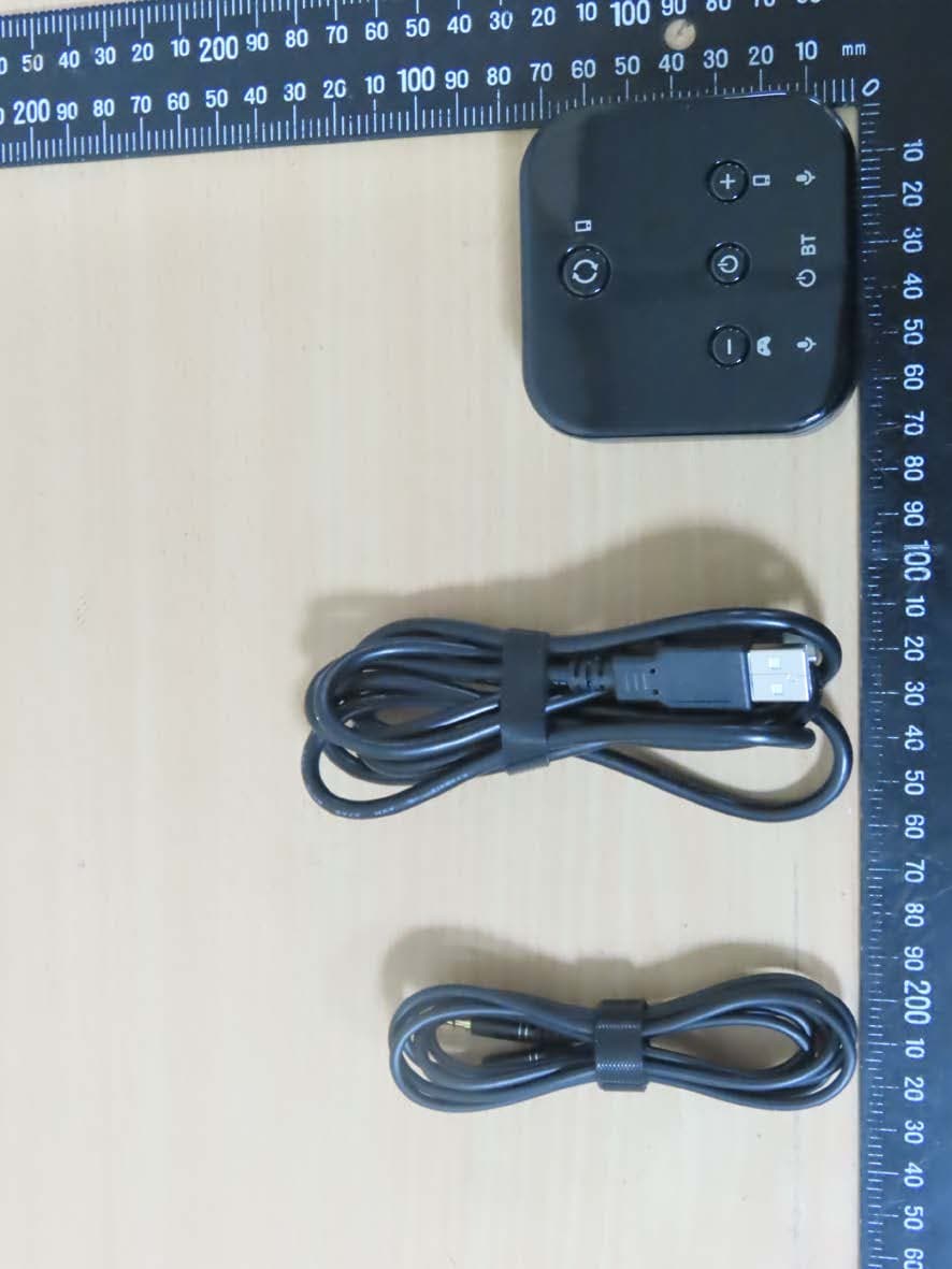
PANBA300M
Dec 08, 2022BT5 Aptx Audio Mixer
Equipment Class
DTS - Digital Transmission System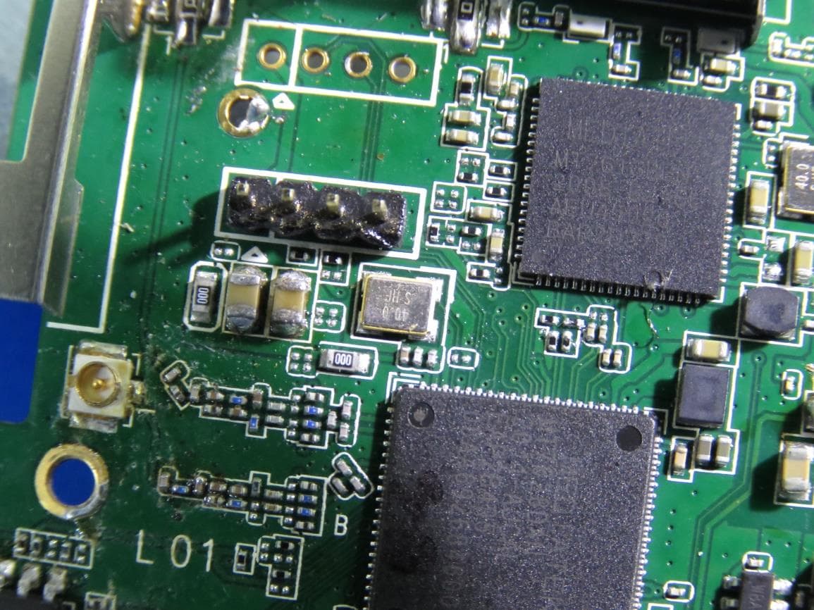
PANWA9563
Dec 17, 2020AC1200 FE Repeater
Equipment Class
NII - Unlicensed National Information Infrastructure TX