PANBT0101MBluetooth Compact Flash Card
CC&C Technologies, Inc.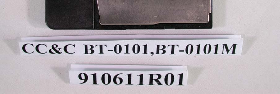
Click to zoom
Application Details
- Equipment Class
- DSS - Part 15 Spread Spectrum Transmitter
- Date of Grant
- Jul 11, 2002
- Application Purpose
- Original Equipment
- Date of Application
- Jul 11, 2002
- Equipment Note
- Bluetooth Compact Flash Card
- Frequency Range
- 2402.00000000 - 2480.00000000
- Company
- CC&C Technologies, Inc.
- Country
- Taiwan
Documents & Files
Document Text
Text extracted from the exhibit documents filed with the FCC. Open a document above to read the original.
Users Manual
8F, 150, Jian Yi Road, Chung Ho City, Taipei County, Taiwan 235, R.O.C. TEL: 886-2-8226-5088 FAX: 886-2-8226-5077 E-mail: [email protected] Inform Letter Dear Customer, According to FCC’s regulation, the following Declaration of Conformity has to be made by a company located in USA. They are: This device has been confirmed to be in compliance with the requirements of ANSI C63.4 & FCC part 15 regulations. The test result has been shown in the ADT test report with number RF910611R01. And this compliance is subject to the following two conditions: (1) This device may not cause harmful interference and, (2) This device must accept any interference received, including interference that may cause undesired operation. This declaration can be a separate sheet and be sure that the following message will be also included in this declaration: 1) Product name, model name and trade name. 2) Company name, and address of the one who is responsible for this declaration. 3) Name, title, telephone and fax number as well as the signature of the contact person. Thanks for your attention. Technologies, Inc.
Users Manual
Bluetooth Compact Flash Card User’s Guide Version 1.0 REGULATORY INFORMATION Federal Communications Commission Interference Statement The equipment has been tested and found to comply with the limits for a Class B digital device, pursuant to part 15 of the FCC Rules. These limits are designed to provide reasonable protection against harmful interference in a residential installation. This equipment generates, uses and can radiate radio frequency energy and, if not installed and used in accordance with the instruction, may cause harmful interference to radio communication. However, there is no guarantee that interference will not occur in a particular installation. If this equipment dose cause harmful interference to radio or television reception, which can be determined by turning the equipment off and on, the user is encouraged to try to correct the interference by one of the following measures: • Reorient or relocate the receiving antenna. • Increase the separation between the equipment and receiver. • Connect the equipment into an outlet on a circuit different from that to which the receiver is connected. • Consult the dealer or an experienced radio/TV technician for help. FCC Caution: To assure continued compliance, (example – use only shielded interface cables when connecting to computer or peripheral devices). Any changes or modification not expressly approved by the party responsible for compliance could void the user’s authority to operate this equipment. This device complies with Part 15 of FCC Rules. Operation is subject to the following two conditions: (1) This device may not cause harmful interference, and (2) this device must accept any interference received, including interference that may cause undesired operation. IMPORTANT NOTE: This transmitter must not be co-located or operating in conjunction with any other antenna or transmitter. EUROPEAN COMMUNITY CE NOTICE Marking by the symbol CE indicates compliance of this equipment to the R&TTE Directive 1999/5/CE. Such marking is indicative that this equipment meets or exceeds the following technical standards: • EN 300 328 • EN 301 489 -1, EN 301 489 -17 • EN 60950 LICENSED SOFTWARE © Copyright 2000 – 2002, WIDCOMM, Inc. (“WIDCOMM”). All rights reserved. WARNING: This software and accompanying documentation are protected by copyright law and international treaties. Unauthorized reproduction or distribution of this software, or any portion of it, may result in severe civil and criminal penalties, and will be prosecuted to the maximum extent possible under the law. Use of this software is governed by the terms of the end user license agreement that accompanies or is included with such software. Unless otherwise noted in the end user license agreement, or herein, no part of the documentation accompanying this software, whether provided in printed or electronic form may be reproduced in any form, or stored in a database or retrieval system, or transmitted in any form or by any means, or used to make any derivative work (such as translation, transformation, or adaptation) without the express, prior written consent of WIDCOMM. Registered Trademark(s) ®, Trademark(s)™, and Service Mark(s) SM WIDCOMM, and the WIDCOMM logo are trademarks of WIDCOMM, Inc. Bluetooth and the Bluetooth logos are trademarks of the Bluetooth SIG, Inc., U.S.A. and licensed to WIDCOMM, Inc. Compaq and iPAQ are trademarks of Compaq Information Technologies Group, L.P. Microsoft, Windows, Outlook, ActiveSync, and the Windows CE logo (graphic only) are either registered trademarks or trademarks of Microsoft Corporation in the United States and/or other countries. Other brand and product names may be registered trademarks, service marks, or trademarks of their respective holders. Bluetooth Complact Flash Card Table of Contents Table of Contents 1 INTRODUCTION TO BTW-CE......................................................................................................... 1 1.1 B LUETOOTH I CON ........................................................................................................................... 1 1.2 A PPLY POWER TO THE B LUETOOTH HARDWARE ............................................................................. 1 1.3 I NSTALLATION ................................................................................................................................2 1.3.1 Integrated (Built-in) Bluetooth Hardware........................................................................... 2 1.3.2 External (Add-on) Bluetooth Hardware.............................................................................. 2 1.3.2.1 Requirements .....................................................................................................2 1.3.2.2 Installation .........................................................................................................2 1.4 U NINSTALL A PRIOR VERSION OF BTW-CE..................................................................................... 3 2 BLUETOOTH CONTROL PANEL: CONFIGURING BTW-CE................................................... 4 2.1 G ENERAL T AB ................................................................................................................................6 2.1.1 Profiles................................................................................................................................ 8 2.1.1.1 Create A New Profile ........................................................................................8 2.1.1.2 Rename or Delete a Profile................................................................................8 2.1.1.3 Save Configuration Settings In A Profile ..........................................................9 2.2 A CCESSIBILITY T AB ...................................................................................................................... 10 2.3 BTW-CE S ERVICE T ABS ..........................................................................…
Text truncated - open the document above for the full version.
Cover Letter(s)
American Telecommunications Certification Body Inc. 6731 Whittier Ave, McLean, VA 22101 July 8, 2002 RE: CC&C TECHNOLOGIES INC. FCC ID: PANBT0101M After a review of the submitted information, I have a few comments on the above referenced Application. 1) The Label contains a space between the Grantee Code and Equipment Product Code. Please provide an updated label with the space removed. 2) Since the output power is so low, the RF exposure statements are not as restrictive. Please remove the following from the users manual (the co-location statement must stay): " This equipment complies with FCC radiation exposure limits set forth for an uncontrolled environment. This equipment should be installed and operated with minimum distance 2.5 cm between the radiator & your body." 3) Since the output power is so low, please remove the reference to the 2.5 cm distance in the RF exposure exhibit (Section 2 & 6.2) and change the classification to only say that it is a portable device. Timothy R. Johnson Examining Engineer mailto: [email protected] The items indicated above must be submitted before processing can continue on the above referenced application. Failure to provide the requested information may result in application termination. Correspondence should be considered part of the permanent submission and may be viewed from the Internet after a Grant of Equipment Authorization is issued. Please do not respond to this correspondence using the email reply button. In order for your response to be processed expeditiously, you must submit your documents through the AmericanTCB.com website. Also, please note that partial responses increase processing time and should not be submitted. Any questions about the content of this correspondence should be directed to the sender.
External Photos
Page 1 ANNEX PHOTOGRAPHS OF EUT Page 2
ID Label/Location Info
Model: BT-0101M Rating: 5V Compact Flash Card Bluetooth Made in Taiwan 0560 MAC:000272000000S/N: 43202000000 FCC ID: PAN WL0101M The Bluetooth Compact Flash Card Label SampleSize: 38*33mm Back Side Front Side Bluetooth Complact Flash card BT-0101M
ID Label/Location Info
Model: BT-0101M Rating: 3.3V Compact Flash Card Bluetooth Made in Taiwan 0560 MAC:000272000000S/N: 43202000000 FCC ID: PANBT0101M The Bluetooth Compact Flash Card Label SampleSize: 38*33mm Back Side Front Side Bluetooth Complact Flash card BT-0101M
Internal Photos
Page 3 Page 4
Operational Description
FCC ID: PANBT0101M ADT No.910611R01 Operational Description The transmitter of the EUT (Bluetooth Compact Flash Card) is powered by host equipment. The antenna is Printed antenna, and there is no antenna connector. Under normal use condition, the user has to keep at least 2.5cm separation distance away from the radiator. For more detailed instruction, please take a look at the users manual. This device is a Frequency Hopping device with 79 hopping frequencies.
RF Exposure Info
FCC ID: PANBT0101M ADT No.: 910611R01 FCC TEST REPORT REPORT NO.: RF910611R1 MODEL NO.: BT-0101 BT-0101M BT100S ACCORDING: FCC Guidelines for Human Exposure IEEE C95.1 APPLICANT:CC&C TECHNOLOGIES INC. ADDRESS: 8F, No. 150, Jian Yi Road, Chung Ho City, Taipei, Taiwan, R.O.C. ISSUED BY:Advance Data Technology Corporation LAB LOCATION:47 14th Lin, Chiapau Tsun, Linko, Taipei, Taiwan, R.O.C. 0528 ILAC MRA Lab Code: 200102-0 FCC ID: PANBT0101M ADT No.: 910611R01 RF Exposure Measurement (Portable Device) 1. Introduction 2.4 GHz frequency band is regarded specially as a dangerous band for its heating harmfulness to the human body. That’s why microwave oven is operating in this frequency band. The manufacturer whose product is working in this frequency band is obligatory to prove the harmfulness of his product. In this document, we try to prove the safety of radiation harmfulness to the human body for our product. The limit for Maximum Permissible Exposure (MPE) specified in FCC 1.1310 is followed. The Gain of the antenna used in this product is measured in a Fully Anechoic Chamber (FAC), and the maximum total power input to the antenna is measured. Through the Friis transmission formula and the maximum gain of the antenna, we can calculate the distance, away from the product, where the limit of MPE is reached. 2. RF Exposure Limit According to FCC 1.1310: The criteria listed in the following table shall be used to evaluate the environmental impact of human exposure to radio-frequency (RF) radiation as specified in 1.1307(b). FCC ID: PANBT0101M ADT No.: 910611R01 LIMITS FOR MAXIMUM PERMISSIBLE EXPOSURE (MPE) Frequency Range (MHz) Electric Field Strength (V/m) Magnetic Field Strength (A/m) Power Density (mW/cm 2 ) Average Time (minutes) (A)Limits For Occupational / Control Exposures 30-30061.40.1631.06 300-1500......F/3006 1500-100,000......56 (B)Limits For General Population / Uncontrolled Exposure 30-30027.50.0730.230 300-1500......F/150030 1500-100,000......1.030 F = Frequency in MHz 3. Friis Formula Friis transmission formula : Pd = (Pout*G) / (4*pi*r 2 ) where Pd = power density in mW/cm 2 Pout = output power to antenna in mW G = gain of antenna in linear scale Pi = 3.1416 R = distance between observation point and center of the radiator in cm Pd is the limit of MPE, 1 mW/cm 2 . If we know the maximum Gain of the antenna and the total power input to the antenna, through the calculation, we will know the distance r where the MPE limit is reached. Ref. : David K. Cheng, Field and Wave Electromagnetics, Second Edition, Page 640, Eq. (11-133). 4. EUT Operating condition The software provided by Manufacturer enabled the EUT to transmit and receive data at lowest, middle and highest channel individually. FCC ID: PANBT0101M ADT No.: 910611R01 5. Test Results 5.1 Antenna Gain The maximum Gain measured in Fully Anechoic Chamber is 0dBi or 1 (numeric). 5.2 Output Power Into Antenna & RF Exposure Distance : CHANNEL CHANNEL FREQUENCY (MHz) OUTPUT POWER TO ANTENNA (mW) MINIMUM ALLOWABLE DISTANCE ( r ) FROM SKIN (Centi-Meter) 024021.390.33 3924411.420.34 7824801.320.32 The minimum allowable distance is very close to the enclosure of the antenna. So, the user has no need to worry about the harmfulness of radiation.
Test Report
The information contained in this letter is intended for the named recipients only. It may contain privileged and confidential information and, if you are not an intended recipient, you must not copy, distribute, or take any action in reliance on it. If you have received this letter in error, please notify the sender immediately by reverse charge telephone call to 01223 692000 and return the original by post. We will reimburse you the postage. Registered Number: 3665875 England VAT Registration Number: 731 9856 07 Cambridge Silicon Radio Limited Cambridge Science Park, Milton Road Cambridge CB4 0WH England Telephone: +44 (0)1223 692000 Fax: +44 (0)1223 692001 http://www.csr.com PROCESS GAIN MEASUREMENTS EXHIBIT. For product FCC ID: PANBT0101M Page 1 of 11 PG Results Filename: BlueCore01_BC01b_PG_Results_v2.1 MEMORANDUM Distribution:Peter Flittner, Robert Young, James Collier cc: Prepared By:Alex Busteed Subject:Results of Processing Gain Tests for FCC Qualification 1 INTRODUCTION This memo presents the results of the Processing Gain (PG) tests carried out for FCC qualification of the Cambridge Silicon Radio BC01B Bluetooth chip. The FCC states that the PG from a hybrid Bluetooth receiver must be greater than 17 dB when measured in accordance with the Continuous Wave (CW) jamming margin method. Testing of the BC01b has found the PG due to the DS section to be approximately 5 dB and the PG due to the FH part to be approximately 15 dB. It is therefore concluded that the BC01B complies with the FCC PG requirements for radio communication systems. The rest of this paper outlines the PG measurement technique and discusses the test results. Appendix A contains a list of test equipment and Appendix B contains a printout of the measurement results. 2 METHOD 2.1 PG Definition The Processing Gain from a frequency hopping communication system is derived from two parts, the FH section and the DS section. The PG due to FH is given by a simple equation and is constant. However measurement of the PG due to DS is a little more complex. One technique is to use the CW jamming margin method. This method measures PG due to DS using the following algorithm: A CW signal generator is stepped in 50kHz increments across the passband of the system, recording at each point the generator level required to produce the 0.1% Packet Error Rate (PER). This is the jammer level. This level is then referenced to the output power of the intended Bluetooth signal and the Jammer to Signal Ratio JSR is thus calculated. The worst 4 Page 2 of 11 PG Results JSR measurements are discarded and the worst remaining JSR is used to calculate the PG due to DS as follows: sysp LJSRSNRG++= min where G p = the processing gain of the system, SNR = the signal to noise ratio required for 0.1% BER, JSR min = minimum J/S ratio and L sys = system losses. 2.2 PG Measurement Technique Figure 1 provides an overview of the PG measurement technique. The measurement is performed in two parts, measurement of the system SNR and measurement of JSR min . Figure 1: PG Measurement Technique The system SNR is calculated using the following algorithm. Generate Bluetooth PRBS-9 packets using a BC01B emulator (1) and a Vector Signal Generator (2). Combine this signal with white noise of a constant level, which is generated using a noise source (4) and a CW Signal Generator (3). Then vary the level of the Bluetooth signal until the BER measured by the BC01B (7) is 0.1%. The resulting SNR is the signal level divided by the Noise level. Page 3 of 11 PG Results The JSR for a given jamming frequency is calculated using the following algorithm. Generate Bluetooth PRBS-9 packets using the BC01B emulator (1) and the Vector Signal Generator (2). Combine this signal with a constant CW tone at the jamming frequency using a CW Signal Generator (5) and a combiner (6). Then vary the level of the Bluetooth signal until the PER measured by the Casira Bluetooth Module (7) is 0.1%. The resulting JSR is the signal level divided by the jamming level. 3 RESULTS 3.1 Overview The measurements found that the PG due to DS caused by the access code in page and inquiry mode is found to be approximately 5dB when the access code is a relatively random mixture of 1's and 0's. A random access code causes the most Inter Symbol Interference (ISI) and hence the worst PG for a hybrid system. Therefore only the results for this access code are used in the PG calculation. The PG due to FH is given as PG FH = 10 log 10 (number of frequency hops) The number of hops in a Bluetooth system is 32, therefore the PG due to FH is approximately 15 dB. When this is added to the PG due to DS, the total PG for the BC01B is approximately 20 dB, above the minimum PG requirement for FCC qualification. 3.2 Detailed Results Test Date:17/11/00 Sample Time: 30 seconds Access Code: c6967e Signal Frequency:2.432GHz Receiver Sensitivity: -88.7 dBm Jammer Signal Level:-85.7 dBm Measured SNR: 18.8dB System Losses: 2dB To calculate processing gain, ignore the worst 20% of data points and then apply the following formula: Page 4 of 11 PG Results sysp LJSRSNRG++= min Where G p = Processing Gain of the module SNR = signal to noise ratio of the module JS min = minimum J/S ratio after the worst 20% of J/S samples have been discarded L sys = System losses A total of 20 samples were taken by stepping the jamming signal frequency offsets in 50kHz increments over the bandwidth of the receiver. The worst 4 samples were found at –500kHz, -450kHz, -400kHz and 500kHz and were discarded. The remaining minimum J/S ratio was found to be -15.4dB at an offset of +350kHz Thus, the processing gain due to direct sequence spreading in page and inquiry mode is dBG p 4.524.158.18=+−= -500-400-300-200-1000100200300400500 -30 -25 -20 -15 -10 -5 0 5 Jamming Frequency Offset (kHz) J/S (dBs) J/S ratio performance for Processing Gain FCC Testing Page 5 of 11 PG Results APPENDIX A - TEST EQUIPMENT LIST Reference:Instrument TypeName 1BlueCore Emulator Boa…
Text truncated - open the document above for the full version.
Test Report
FCC ID: PANBT0101M Report No.: RF910611R011Issued: July 1, 2002 FCC TEST REPORT REPORT NO.: RF910611R01 MODEL NO.: BT-0101 (For other models please refer to page 6) RECEIVED: June 11, 2002 TESTED: June 13 ~ June 24, 2002 APPLICANT: CC&C TECHNOLOGIES INC. ADDRESS: 8F, 150, Jian Yi Road, Chung Ho City, Taipei, Taiwan, R.O.C. ISSUED BY: Advance Data Technology Corporation LAB LOCATION: 47 14th Lin, Chiapau Tsun, Linko, Taipei, Taiwan, R.O.C. This test report consists of 62 pages in total. It may be duplicated completely for legal use with the approval of the applicant. It should not be reproduced except in full, without the written approval of our laboratory. The client should not use it to claim product endorsement by CNLA, NVLAP or any government agencies. The test results in the report only apply to the tested sample. 0528 ILAC MRA Lab Code: 200102-0 FCC ID: PANBT0101M Report No.: RF910611R012Issued: July 1, 2002 TABLE OF CONTENTS 1CERTIFICATION .......................................................................................................... 4 2SUMMARY OF TEST RESULTS .................................................................................. 5 3GENERAL INFORMATION........................................................................................... 6 3.1GENERAL DESCRIPTION OF EUT............................................................................. 6 3.2DESCRIPTION OF TEST MODES............................................................................... 7 3.3GENERAL DESCRIPTION OF APPLIED STANDARDS .............................................. 7 3.4DESCRIPTION OF SUPPORT UNITS ......................................................................... 8 4TEST PROCEDURES AND RESULTS ........................................................................ 9 4.1CONDUCTED EMISSION MEASUREMENT ............................................................... 9 4.1.1LIMITS OF CONDUCTED EMISSION MEASUREMENT....................................... 9 4.1.2TEST INSTRUMENTS............................................................................................ 9 4.1.3TEST PROCEDURES .......................................................................................... 10 4.1.4DEVIATION FROM TEST STANDARD ................................................................ 10 4.1.5TEST SETUP........................................................................................................ 11 4.1.6TEST RESULTS ................................................................................................... 12 4.2NUMBER OF HOPPING FREQUENCY USED .......................................................... 18 4.2.1LIMIT OF HOPPING FREQUENCY USED........................................................... 18 4.2.2TEST INSTRUMENTS.......................................................................................... 18 4.2.3TEST PROCEDURES .......................................................................................... 19 4.2.4DEVIATION FROM TEST STANDARD ................................................................ 19 4.2.5TEST SETUP........................................................................................................ 19 4.2.6TEST RESULTS ................................................................................................... 19 4.3DWELL TIME ON EACH CHANNEL .......................................................................... 22 4.3.1LIMIT OF DWELL TIME USED ............................................................................. 22 4.3.2TEST INSTRUMENTS.......................................................................................... 22 4.3.3TEST PROCEDURES .......................................................................................... 23 4.3.4DEVIATION FROM TEST STANDARD ................................................................ 23 4.3.5TEST SETUP........................................................................................................ 23 4.3.6TEST RESULTS ................................................................................................... 24 4.4CHANNEL BANDWIDTH............................................................................................ 28 4.4.1LIMITS OF CHANNEL BANDWIDTH ................................................................... 28 4.4.2TEST INSTRUMENTS.......................................................................................... 28 4.4.3TEST PROCEDURE............................................................................................. 29 4.4.4DEVIATION FROM TEST STANDARD ................................................................ 29 4.4.5TEST SETUP........................................................................................................ 29 4.4.6EUT OPERATING CONDITION............................................................................ 29 FCC ID: PANBT0101M Report No.: RF910611R013Issued: July 1, 2002 4.4.7TEST RESULTS ................................................................................................... 30 4.5HOPPING CHANNEL SEPARATION ......................................................................... 34 4.5.1LIMIT OF HOPPING CHANNEL SEPARATION ................................................... 34 4.5.2TEST INSTRUMENTS.......................................................................................... 34 4.5.3TEST PROCEDURES .......................................................................................... 35 4.5.4DEVIATION FROM TEST STANDARD ................................................................ 35 4.5.5TEST SETUP........................................................................................................ 35 4.5.6TEST RESULTS ................................................................................................... 36 4.6MAXIMUM PEAK OUTPUT POWER ......................................................................... …
Text truncated - open the document above for the full version.
Test Report
FCC ID: PANBT0101M Report No.: RF910611R0134Issued: July 1, 2002 4.5 HOPPING CHANNEL SEPARATION 4.5.1 LIMIT OF HOPPING CHANNEL SEPARATION At least 25kHz or 20dB bandwidth (whichever is greater). 4.5.2 TEST INSTRUMENTS Description & ManufacturerModel No.Serial No.Calibrated Until SPECTRUM ANALYZERFSEK30100049July 17, 2002 NOTES: 1.The measurement uncertainty is less than +/- 2.6dB, which is calculated as per the NAMAS document NIS81. 2.The calibration interval of the above test instruments is 12 months. And the calibrations are traceable to NML/ROC and NIST/USA. FCC ID: PANBT0101M Report No.: RF910611R0135Issued: July 1, 2002 4.5.3 TEST PROCEDURES 1. Check the calibration of the measuring instrument using either an internal calibrator or a known signal from an external generator. 2. Turn on the EUT and connect it to measurement instrument. Then set it to any one convenient frequency within its operating range. 3. By using the MaxHold function record the separation of two adjacent channels. 4. Measure the frequency difference of these two adjacent channels by SA MARK function. And then plot the result on SA screen. 5. Repeat above procedures until all frequencies measured were complete. 4.5.4 DEVIATION FROM TEST STANDARD No deviation 4.5.5 TEST SETUP EUT SPECTRUM ANALYZER FCC ID: PANBT0101M Report No.: RF910611R0136Issued: July 1, 2002 4.5.6 TEST RESULTS Channel Frequency (MHz) Adjacent Channel Separation Minimum Limit (kHz) Pass / Fail 024021MHz864.00PASS 3924411MHz846.00PASS 7824801MHz864.00PASS The minimum limit is 20dB bandwidth. Test results please refer to next three pages. FCC ID: PANBT0101M Report No.: RF910611R0137Issued: July 1, 2002 Channel 0 FCC ID: PANBT0101M Report No.: RF910611R0138Issued: July 1, 2002 Channel 39 FCC ID: PANBT0101M Report No.: RF910611R0139Issued: July 1, 2002 Channel 78 FCC ID: PANBT0101M Report No.: RF910611R0140Issued: July 1, 2002 4.6 MAXIMUM PEAK OUTPUT POWER 4.6.1 LIMITS OF MAXIMUM PEAK OUTPUT POWER MEASUREMENT The Limit of Maximum Peak Output Power Measurement is 30dBm. 4.6.2 INSTRUMENTS Description & ManufacturerModel No.Serial No.Calibrated Until SPECTRUM ANALYZERFSEK30100049July 17, 2002 NOTES: 1.The measurement uncertainty is less than +/- 2.6dB, which is calculated as per the NAMAS document NIS81. 2.The calibration interval of the above test instruments is 12 months. And the calibrations are traceable to NML/ROC and NIST/USA. FCC ID: PANBT0101M Report No.: RF910611R0141Issued: July 1, 2002 4.6.3 TEST PROCEDURES 1. Check the calibration of the measuring instrument using either an internal calibrator or a known signal from an external generator. 2. Turn on the EUT and connect it to measurement instrument. Then set it to any one convenient frequency within its operating range. Set a reference level on the measuring instrument equal to the highest peak value. 3. The center frequency of the spectrum analyzer is set to the fundamental frequency and using 2 MHz RBW and 3 MHz VBW. 4. Measure the frequency difference of two frequencies that were attenuated 20dB from the reference level. Record the frequency difference as the emission bandwidth. 5. Repeat above procedures until all frequencies measured were complete. 4.6.4 DEVIATION FROM TEST STANDARD No deviation 4.6.5 TEST SETUP For the actual test configuration, please refer to the related Item – Photographs of the Test Configuration. EUT SPECTRUM ANALYZER FCC ID: PANBT0101M Report No.: RF910611R0142Issued: July 1, 2002 4.6.6 EUT OPERATING CONDITION The software provided by client enabled the EUT to transmit and receive data at lowest, middle and highest channel frequencies individually. 4.6.7 TEST RESULTS Output Power Into Antenna: CHANNEL CHANNEL FREQUENCY (MHz) PEAK POWER OUTPUT (dBm) PEAK POWER LIMIT (dBm) PASS/FAIL 024021.4230PASS 3924411.5230PASS 7824801.2130PASS FCC ID: PANBT0101M Report No.: RF910611R0143Issued: July 1, 2002 Channel 0 FCC ID: PANBT0101M Report No.: RF910611R0144Issued: July 1, 2002 Channel 39 FCC ID: PANBT0101M Report No.: RF910611R0145Issued: July 1, 2002 Channel 78 FCC ID: PANBT0101M Report No.: RF910611R0146Issued: July 1, 2002 4.7 RADIATED EMISSION MEASUREMENT 4.7.1 LIMITS OF RADIATED EMISSION MEASUREMENT Field strength limits are at the distance of 3 meters, emissions radiated outside of the specified bands, shall be according to the general radiated limits in 15.209 as following: Field Strength of Fundamental Frequencies (MHz) uV/mdBuV/m 30-8810040.0 88-21615043.5 216-96020046.0 Above 96050054.0 NOTE: 1. The lower limit shall apply at the transition frequencies. 2. Emission level (dBuV/m) = 20 log Emission level (uV/m). 3. As shown in 15.35(b), for frequencies above 1000MHz, the field strength limits are based on average detector, however, the peak field strength of any emission shall not exceed the maximum permitted average …
Text truncated - open the document above for the full version.
Contact Information
Applicant
Cooper Hou(Product Manager)
Technical Contact
Advance Data Technology CorporationAlan Lane
[email protected]+886-3-327-0910
13-1, Lane 19, WenShan 3rd., St. · Taoyuan · Taiwan
Non-Technical Contact
Advance Data Technology CorporationAlan Lane
[email protected]+886-3-327-0910
Test Firm
Bureau Veritas CPS (H.K.) Ltd. Taoyuan BranchTommy Wu
Technical Specifications
| # | Rule Parts | Frequency Range | Power Output |
|---|---|---|---|
| 1 | 15C | 2.40 GHz - 2.48 GHz | 1.42 mW |
Other Applications from CC&C Technologies, Inc.
PANBM3095
Jun 24, 2026Bluetooth v5.4 APTX LE Audio RX Module
Equipment Class
DSS - Part 15 Spread Spectrum Transmitter
PANBA550T
Sep 26, 2024Triple source to BT5.3 LE Audio Transmitter
Equipment Class
DSS - Part 15 Spread Spectrum Transmitter
PANBA55T
Sep 26, 2024Dual source to BT5.3 LE Audio Transmitter
Equipment Class
DTS - Digital Transmission System
PANBA300M
Dec 08, 2022BT5 Aptx Audio Mixer
Equipment Class
DTS - Digital Transmission System
PANWA9563
Dec 17, 2020AC1200 FE Repeater
Equipment Class
NII - Unlicensed National Information Infrastructure TX