PANBT0310Bluetooth Wireless/USB Keyboard
CC&C Technologies, Inc.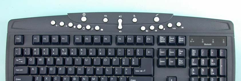
Click to zoom
Application Details
- Equipment Class
- DSS - Part 15 Spread Spectrum Transmitter
- Date of Grant
- Mar 02, 2004
- Application Purpose
- Original Equipment
- Date of Application
- Mar 02, 2004
- Equipment Note
- Bluetooth Wireless/USB Keyboard
- Frequency Range
- 2402.00000000 - 2480.00000000
- Company
- CC&C Technologies, Inc.
- Country
- Taiwan
Documents & Files
Document Text
Text extracted from the exhibit documents filed with the FCC. Open a document above to read the original.
Users Manual
BT-0310 Bluetooth Keyboard USER’S MANUAL Version 1.0 July 2003 Confidential 2 BLUETOOTH KEYBOARD USER’S MANUAL REGULATION INFORMATION The Bluetooth Keyboard must be installed and used in strict accordance with the manufacturer’s instructions. This device complies with the following radio frequency and safety standards. FCC (Federal Communications Commission) This device complies with Part 15 of FCC Rules. Operation is subject to the following two conditions: 1. This device may not cause harmful interference. 2. This device must accept any interference that may cause undesired operation. This transmitter must not be co-located or operating in conjunction with any other antenna or transmitter. The equipment has been tested and found to comply with the limits for a Class B Digital Device, pursuant to part 15 of the FCC Rules. These limits are designed to provide reasonable protection against harmful interference in a residential installation. This equipment generates, uses and can radiate radio frequency energy and, if not installed and used in accordance with the instruction, may cause harmful interference to radio communication. However, there is no grantee that interference will not occur in a particular installation. If this equipment dose cause harmful interference to radio or television reception, which can be determined by turning the equipment off and on, the user is encouraged to try to correct the interference by one or more of the following measures: --Reorient or relocate the receiving antenna. --Increase the separation between the equipment and receiver. --Connect the equipment into an outlet on a circuit different from that to which the receiver is connected. --Consult the dealer or an experienced radio/TV technician for help. Notice: The Part 15 radio device operates on a non-interference basis with other devices operating at this frequency. Any changes or modification not expressly approved by the party responsible could void the user’s authority to operate the device. R&TTE Directive This device complies with the specifications listed below: • ETS 301 489 -1 & -17 General EMC requirements for Radio equipment. • ETS 300 328 Technical requirements for Radio equipment. • EN60950 Safety Requirements for Radio equipment Confidential 3 BLUETOOTH KEYBOARD USER’S MANUAL LICENSED SOFTWARE © Copyright 2000 – 2003, WIDCOMM, Inc. (“WIDCOMM”). All rights reserved. Warning: This software and accompanying documentation are protected by copyright law and international treaties. Unauthorized reproduction or distribution of this software, or any portion of it, may result in severe civil and criminal penalties, and will be prosecuted to the maximum extent possible under the law. Use of this software is governed by the terms of the end user license agreement that accompanies or is included with such software. Unless otherwise noted in the end user license agreement, or herein, no part of the documentation accompanying this software, whether provided in printed or electronic form may be reproduced in any form, or stored in a database or retrieval system, or transmitted in any form or by any means, or used to make any derivative work (such as translation, transformation, or adaptation) without the express, prior written consent of WIDCOMM. Trademark(s) ™ and Registered Trademark(s) ® WIDCOMM and the WIDCOMM logo are trademarks of WIDCOMM, Inc. Bluetooth and the Bluetooth logos are trademarks owned by Bluetooth SIG, Inc., U.S.A. and licensed to WIDCOMM, Inc. Microsoft, Windows, Outlook are registered trademarks of Microsoft Corporation. Other brand and product names may be registered trademarks or trademarks of their respective holders. Confidential 4 BLUETOOTH KEYBOARD USER’S MANUAL Contents 1. Introduction ......................................................................... 5 2. Introducing Bluetooth Keyboard....................................... 6 3. Hardware Installation.......................................................... 8 4. Create a Bluetooth Keyboard Connection ....................... 9 Confidential 5 BLUETOOTH KEYBOARD USER’S MANUAL 1. Introduction Welcome to join Bluetooth wireless world. This installation guide contains introductions for setting up the Bluetooth Keyboard. System Requirements z Processor: Intel Celeron / Pentium III / Pentium IV; AMD Duron / Athlon z Operating System: Microsoft Windows 2000 / XP z Bluetooth USB Dongle Device z Widcomm software version 1.4 or latest What’s in this package z Bluetooth keyboard z USB cable z User’s manual CD z Quick start guide How to begin z You must set up the Bluetooth Keyboard Hardware. Turn to page 8. z You must create the Bluetooth Connection. Turn to page 9. Confidential 6 BLUETOOTH KEYBOARD USER’S MANUAL 2. Introducing Bluetooth Keyboard USB Connecter Multimedia Function Keys Keyboard Displays Connect Button Battery Room Confidential 7 BLUETOOTH KEYBOARD USER’S MANUAL Multimedia Function Keys WWW-Back Volume up WWW-Forward Volume down WWW-Refresh Mute WWW-Stop Next track Search Previous track Favorites Stop WWW Play/pause E-mail Media select Sleep Keyboard Displays z Shows when Num Lock, Cap Lock, Scroll Lock are turned on. z Bluetooth status LED shows when Low Battery indicator and flashing when keyboard connected with host. z All LEDs flashing when keyboard is in the discoverable mode. USB Connecter z When standard USB keyboard, plug the USB cable to this connecter and host USB port. Connect Button z If re-pair, you can press connect button to clear the virtucable. Battery Room z 4 AA Batteries Confidential 8 BLUETOOTH KEYBOARD USER’S MANUAL 3. Hardware Installation The keyboard uses 4 pieces of alkaline batteries. Rechargeable batteries are not recommended. Step1. Remove the battery compartment cover from the bottom of Bluetooth keyboard. Step2. Insert the batteries. Make sure that the “+” and “-“ in each battery matches the “+” and “-“ on each slot. Step3. Put the cover on. Confidential 9 BLUETOOTH KEYBOARD USER’S M…
Text truncated - open the document above for the full version.
Cover Letter(s)
American Telecommunications Certification Body Inc. 6731 Whittier Ave, McLean, VA 22101 February 24, 2004 RE: FCC ID: PANBT0310_ATCB001136 Attention: Ellis Wu I have a few comments on this Application. 1. FYI – no action needed. Please note that Bluetooth devices are classified as Frequency Hopping devices under equipment code DSS and have a frequency range of 2402 to 2480MHz. The frequency range of 2412 to 2462 is generally DTS WLAN frequencies. I have corrected the 731 on this issue. 2. FYI – no action needed at this time. Please note that because the device under question is the Bluetooth transmitter portion of the keyboard, the block diagram should provide detailed information on the Bluetooth operation. 3. Please note that on the bottom of page 7 of the internal photos (page 4 of the pdf document) there appears to be a shield that has not been removed and there appears to be no photo of what is underneath that shield. 4. Please note that there appears to be more than sufficient room on the keyboard to place the 2 condition statement as required by Part 15.19(a)(3). Please provide evidence that this label is placed on the product as required. 5. Please note that this is a wireless keyboard that can and probably will be used in the lap. Consequently, while in the wired mode a 20 cm separation may be possible, it would not seem appropriate to use the 20cm mobile separation distance when in the wireless Bluetooth mode. Also, please note that the power of the device is sufficiently under the FCC SAR limits to warrant no SAR testing (i.e. only 2.2mW conducted and 3mw eirp). As such the device should be listed as a portable device that meets rf exposure requirements. There would then be no reason to specify a minimum 20cm separation distance. Please correct the rf exposure statement to that of a portable device meeting rf exposure compliance for the general/uncontrolled environment. 6. It appears from the setup photos that you have run the Bluetooth device from an ac power adapter instead of the batteries in the keyboard. Please explain. Also, if the card on the table in the setup photo is the Bluetooth device, please explain why it was not tested inside the keyboard. Dennis Ward mailto:[email protected] The items indicated above must be submitted before processing can continue on the above referenced application. Failure to provide the requested information may result in application termination. Correspondence should be considered part of the permanent submission and may be viewed from the Internet after a Grant of Equipment Authorization is issued. Please do not respond to this correspondence using the email reply button. In order for your response to be processed expeditiously, you must submit your documents through the AmericanTCB.com website. Also, please note that partial responses increase processing time and should not be submitted. Any questions about the content of this correspondence should be directed to the sender.
External Photos
Page 1 CONSTRUCTION PHOTOS OF EUT Page 2 Page 3
ID Label/Location Info
~2040426.bmp (247 x 279 x 24)
Internal Photos
Page 4 Page 5 Page 6 Page 7 Page 8
Operational Description
FCC ID: PANBT0310 Report No.RF921112R02 Operational Description The transmitter of the EUT (Bluetooth Wireless/USB Keyboard) is powered by 6V Batteries. The type of antenna is printed antenna. The output power of this device is very low. Under normal use condition, the transmitter and the receiver are quite close, so high EIRP power is neither necessary nor allowed because of interference. This device is a Frequency Hopping device with 79 hopping frequencies. The declared output power is only +10dBm.
Test Report
FCC ID: PANBT0310 Report No.: RF921112R021Issued: November 21, 2003 FCC TEST REPORT REPORT NO.: RF921112R02 MODEL NO.: BT-0310 RECEIVED: November 12, 2003 TESTED: November 19 ~ November 20, 2003 APPLICANT: CC&C TECHNOLOGIES INC. ADDRESS: 8F, 150, Jian Yi Road, Chung Ho City, Taipei County, Taiwan 235, R.O.C. ISSUED BY: Advance Data Technology Corporation LAB LOCATION: 47 14th Lin, Chiapau Tsun, Linko, Taipei, Taiwan, R.O.C. This test report consists of 55 pages in total. It may be duplicated completely for legal use with the approval of the applicant. It should not be reproduced except in full, without the written approval of our laboratory. The client should not use it to claim product endorsement by CNLA, NVLAP or any government agencies. The test results in the report only apply to the tested sample. 0528 ILAC MRA Lab Code: 200102-0 FCC ID: PANBT0310 Report No.: RF921112R022Issued: November 21, 2003 TABLE OF CONTENTS 1CERTIFICATION .......................................................................................................... 4 2SUMMARY OF TEST RESULTS .................................................................................. 5 3GENERAL INFORMATION........................................................................................... 6 3.1GENERAL DESCRIPTION OF EUT............................................................................. 6 3.2DESCRIPTION OF TEST MODES............................................................................... 7 3.3GENERAL DESCRIPTION OF APPLIED STANDARDS .............................................. 7 3.4DESCRIPTION OF SUPPORT UNITS ......................................................................... 8 4TEST PROCEDURES AND RESULTS ........................................................................ 9 4.1CONDUCTED EMISSION MEASUREMENT ............................................................... 9 4.2NUMBER OF HOPPING FREQUENCY USED ............................................................ 9 4.2.1 LIMIT OF HOPPING FREQUENCY USED .................................................................. 9 4.2.2 TEST INSTRUMENTS.................................................................................................. 9 4.2.3 TEST PROCEDURES ................................................................................................ 10 4.2.4 DEVIATION FROM TEST STANDARD ...................................................................... 10 4.2.5 TEST SETUP ............................................................................................................. 11 4.2.6 TEST RESULTS ......................................................................................................... 11 4.3DWELL TIME ON EACH CHANNEL .......................................................................... 14 4.3.1 LIMIT OF DWELL TIME USED................................................................................... 14 4.3.2 TEST INSTRUMENTS................................................................................................ 14 4.3.3 TEST PROCEDURES ................................................................................................ 15 4.3.4 DEVIATION FROM TEST STANDARD ...................................................................... 15 4.3.5 TEST SETUP ............................................................................................................. 15 4.3.6 TEST RESULTS ......................................................................................................... 16 4.4CHANNEL BANDWIDTH............................................................................................ 22 4.4.1 LIMITS OF CHANNEL BANDWIDTH ......................................................................... 22 4.4.2 TEST INSTRUMENTS................................................................................................ 22 4.4.3 TEST PROCEDURE................................................................................................... 23 4.4.4 DEVIATION FROM TEST STANDARD ...................................................................... 23 4.4.5 TEST SETUP ............................................................................................................. 23 4.4.6 EUT OPERATING CONDITION ................................................................................. 23 4.4.7 TEST RESULTS ......................................................................................................... 24 4.5HOPPING CHANNEL SEPARATION ......................................................................... 28 4.5.1 LIMIT OF HOPPING CHANNEL SEPARATION ......................................................... 28 4.5.2 TEST INSTRUMENTS................................................................................................ 28 4.5.3 TEST PROCEDURES ................................................................................................ 29 FCC ID: PANBT0310 Report No.: RF921112R023Issued: November 21, 2003 4.5.4 DEVIATION FROM TEST STANDARD ...................................................................... 29 4.5.5 TEST SETUP ............................................................................................................. 29 4.5.6 TEST RESULTS ......................................................................................................... 30 4.6MAXIMUM PEAK OUTPUT POWER –USING POWER METTER............................. 34 4.6.1 LIMITS OF MAXIMUM PEAK OUTPUT POWER MEASUREMENT.......................... 34 4.6.2 INSTRUMENTS.......................................................................................................... 34 4.6.3 TEST PROCEDURES ................................................................................................ 35 4.6.4 DEVIATION FROM TEST STANDARD ...................................................................... 35 4.6.5 TEST SETUP ..........................................................…
Text truncated - open the document above for the full version.
Test Report
FCC ID: PANBT0310 Report No.: RF921112R0231Issued: November 21, 2003 Channel 0 FCC ID: PANBT0310 Report No.: RF921112R0232Issued: November 21, 2003 Channel 39 FCC ID: PANBT0310 Report No.: RF921112R0233Issued: November 21, 2003 Channel 78 FCC ID: PANBT0310 Report No.: RF921112R0234Issued: November 21, 2003 4.6 MAXIMUM PEAK OUTPUT POWER –USING POWER METTER 4.6.1 LIMITS OF MAXIMUM PEAK OUTPUT POWER MEASUREMENT The Maximum Peak Output Power Measurement is 30dBm. 4.6.2 INSTRUMENTS Description & ManufacturerModel No.Serial No.Calibrated Until SPECTRUM ANALYEERFSEK30100049Aug. 12, 2004 NOTE: The calibration interval of the above test instruments is 12 months and the calibrations are traceable to NML/ROC and NIST/USA. FCC ID: PANBT0310 Report No.: RF921112R0235Issued: November 21, 2003 4.6.3 TEST PROCEDURES 1. Check the calibration of the measuring instrument using either an internal calibrator or a known signal from an external generator. 2. Turn on the EUT and connect it to measurement instrument. Then set it to any one convenient frequency within its operating range. Set a reference level on the measuring instrument equal to the highest peak value. 3. The center frequency of the spectrum analyzer is set to the fundamental frequency and using 3 MHz RBW and 3 MHz VBW. 4. Measure the frequency difference of two frequencies that were attenuated 20dB from the reference level. Record the frequency difference as the emission bandwidth. 5. Repeat above procedures until all frequencies measured were complete. 4.6.4 DEVIATION FROM TEST STANDARD No deviation FCC ID: PANBT0310 Report No.: RF921112R0236Issued: November 21, 2003 4.6.5 TEST SETUP For the actual test configuration, please refer to the related Item – Photographs of the Test Configuration. 4.6.6 EUT OPERATING CONDITION The software provided by client enabled the EUT to transmit and receive data at lowest, middle and highest channel frequencies individually. EUTPOWER METER FCC ID: PANBT0310 Report No.: RF921112R0237Issued: November 21, 2003 4.6.7 TEST RESULTS Output Power to Antenna: CHANNEL CHANNEL FREQUENCY (MHz) PEAK POWER OUTPUT (dBm) PEAK POWER LIMIT (dBm) PASS/FAIL 024023.3030PASS 3924413.4630PASS 7824802.7730PASS FCC ID: PANBT0310 Report No.: RF921112R0238Issued: November 21, 2003 Channel 0 FCC ID: PANBT0310 Report No.: RF921112R0239Issued: November 21, 2003 Channel 39 FCC ID: PANBT0310 Report No.: RF921112R0240Issued: November 21, 2003 Channel 78 FCC ID: PANBT0310 Report No.: RF921112R0241Issued: November 21, 2003 4.7 RADIATED EMISSION MEASUREMENT 4.7.1 LIMITS OF RADIATED EMISSION MEASUREMENT Emissions radiated outside of the specified bands, shall be according to the general radiated limits in 15.209 as following: Frequencies (MHz) Field strength (microvolts/meter) Measurement distance (meters) 0.009-0.4902400/F(kHz)300 0.490-1.70524000/F(kHz)30 1.705-30.03030 30-881003 88-2161503 216-9602003 Above 9605003 As shown in 15.35(b), for frequencies above 1000MHz, the field strength limits are based on average detector, however, the peak field strength of any emission shall not exceed the maximum permitted average limits, specified above by more than 20dB under any condition of modulation. FCC ID: PANBT0310 Report No.: RF921112R0242Issued: November 21, 2003 4.7.2 TEST INSTRUMENTS DESCRIPTION & MANUFACTURERMODEL NO.SERIAL NO. CALIBRATED UNTIL * HP Spectrum Analyzer8594E3911A07465July 07, 2004 * HP Preamplifier8447D2432A03504June 10, 2004 * HP Preamplifier8449B3008A01292Aug. 11, 2004 SCHAFFNER Tunable Dipole Antenna SCHWARZBECK Tunable Dipole Antenna VHBA 9123 UHA 9105 459 977 Nov. 22, 2003 * ROHDE & SCHWARZ TEST RECEIVER ESMI 839013/007 839379/002 Feb. 13, 2004 *Schwarzbeck AntennaVULB9168137Apr. 03, 2004 * SCHWARZBECK Horn Antenna BBHA9120-D1D130June 30, 2004 * EMCO Horn Antenna31159312-4192Mar. 23, 2004 *ADT. Turn TableTT1000306NA *ADT. TowerAT1000306NA *Software ADT_Radiated_V 5.14 NANA *TIMES RF cableLL142CABLE-CH6-01Apr. 30, 2004 NOTE:1. The calibration interval of the above test instruments is 12 months. And the calibrations are traceable to NML/ROC and NIST/USA. 2. “*” = These equipment are used for the final measurement. 3. The horn antenna and HP preamplifier (model: 8449B) are used only for the measurement of emission frequency above 1GHz if tested. 4. The test was performed in ADT Chamber No. 6. FCC ID: PANBT0310 Report No.: RF921112R0243Issued: November 21, 2003 4.7.3 TEST PROCEDURES a. The EUT was placed on the top of a rotating table 0.8 meters above the ground at a 10 meter open area test site. The table was rotated 360 degrees to determine the position of the highest radiation. b. The EUT was set 3 meters away from the interference-receiving antenna, which was mounted on the top of a variable-height antenna tower. c. The antenna is a broadband antenna, and its height is varied from one meter to four meters above the ground to determine the maximum value of the field strength. Both horizontal and vertical polarizations of the antenna are set to make the measurement. d. For each suspected emission, the EUT was arranged to its worst case and then the antenna was tuned to heights from 1 meter to 4 meters and the rotatable table was turned from 0 degrees to 360 degrees to find the maximum reading. e. The test-receiver system was set to Peak Detect Function and Specified Bandwidth with Maximum Hold Mode. f. If the emission level of the EUT in peak mode was 10 dB lower than the limit specified, then testing could be stopped and the peak values of the EUT would be reported. Otherwise the emissions that did not have 10 dB margin would be re- tested one by one using peak, quasi-peak or average method as specified and then reported in a data sheet. NOTE: 1. The resolution bandwidth and video bandwidth of test receiver/spectrum analyzer is 120kHz for Peak detection (PK) and Quasi-peak detection (QP) at frequency below 1GHz. 2. The resolution bandwidth and video bandwidth of test receiver/spectrum analyzer is 1 MHz for Peak detection at f…
Text truncated - open the document above for the full version.
Test Setup Photos
FCC ID: PANBT0310 Report No.: RF921112R0254Issued: November 21, 2003 5 PHOTOGRAPHS OF THE TEST CONFIGURATION RADIATED EMISSION TEST
Contact Information
Applicant
Cooper Hou(Product Manager)
Technical Contact
Advance Data Technology CorporationEllis Wu
[email protected]886-3-327-0910
13-1, Lane19, WenShan 3rd ., St., · Taoyuan · Taiwan
Test Firm
Bureau Veritas CPS (H.K.) Ltd. Taoyuan BranchTommy Wu
Technical Specifications
| # | Rule Parts | Frequency Range | Power Output |
|---|---|---|---|
| 1 | 15C | 2.40 GHz - 2.48 GHz | 2.00 mW |
Other Applications from CC&C Technologies, Inc.
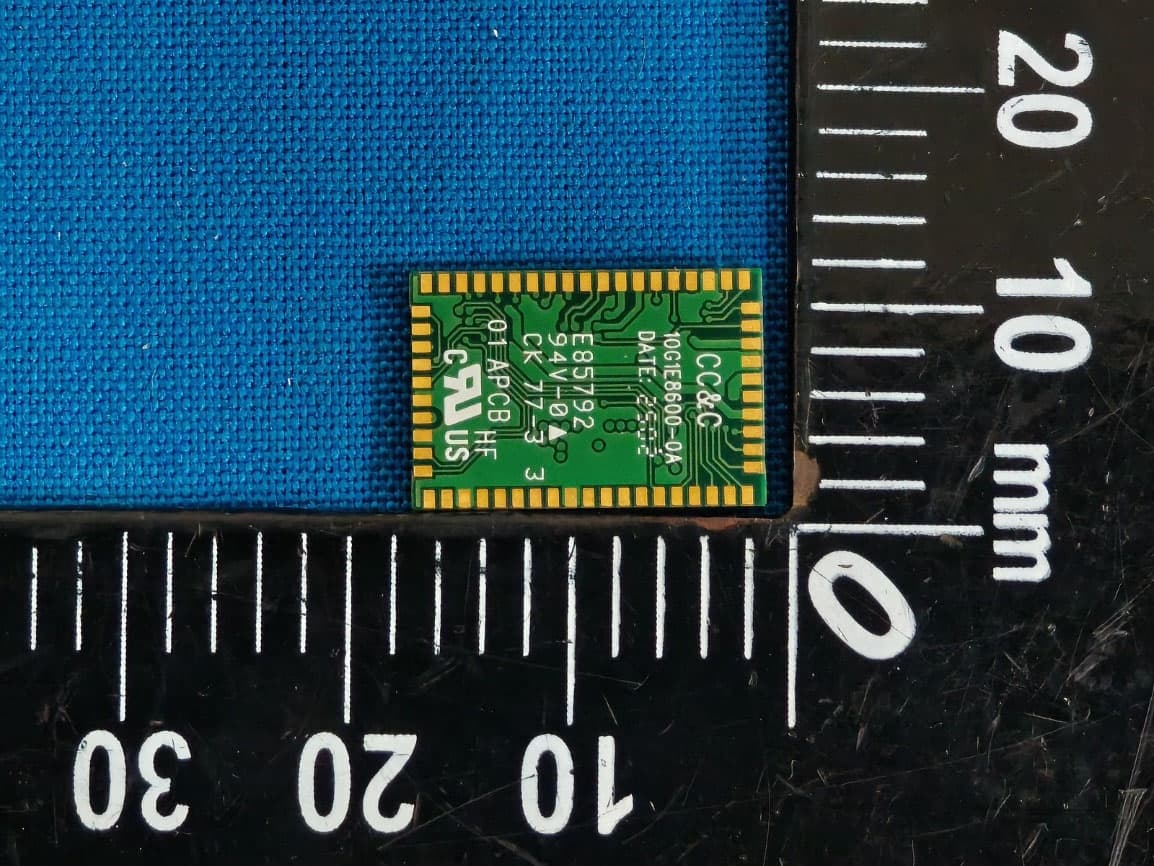
PANBM3095
Jun 24, 2026Bluetooth v5.4 APTX LE Audio RX Module
Equipment Class
DSS - Part 15 Spread Spectrum Transmitter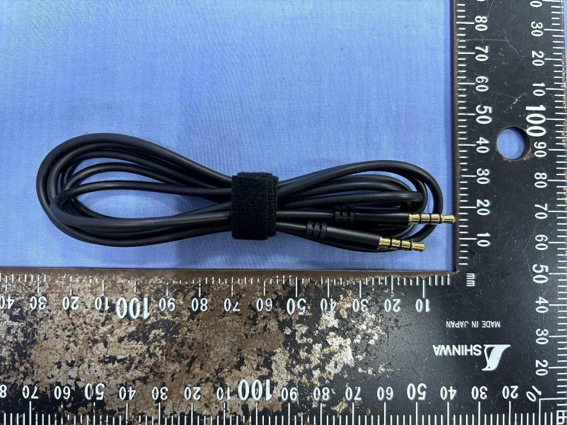
PANBA550T
Sep 26, 2024Triple source to BT5.3 LE Audio Transmitter
Equipment Class
DSS - Part 15 Spread Spectrum Transmitter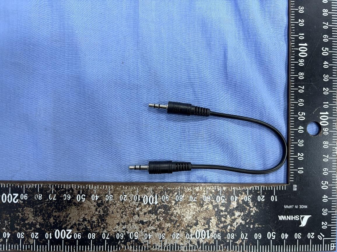
PANBA55T
Sep 26, 2024Dual source to BT5.3 LE Audio Transmitter
Equipment Class
DTS - Digital Transmission System
PANBA300M
Dec 08, 2022BT5 Aptx Audio Mixer
Equipment Class
DTS - Digital Transmission System
PANWA9563
Dec 17, 2020AC1200 FE Repeater
Equipment Class
NII - Unlicensed National Information Infrastructure TX