PANWL1101PCMCIA Radio Card with Integrated Antenna
CC&C Technologies, Inc.
Click to zoom
Application Details
- Equipment Class
- DSS - Part 15 Spread Spectrum Transmitter
- Date of Grant
- Jun 12, 2002
- Application Purpose
- Original Equipment
- Date of Application
- Jun 12, 2002
- Equipment Note
- PCMCIA Radio Card with Integrated Antenna
- Frequency Range
- 2412.00000000 - 2462.00000000
- Company
- CC&C Technologies, Inc.
- Country
- Taiwan
Documents & Files
Document Text
Text extracted from the exhibit documents filed with the FCC. Open a document above to read the original.
Users Manual
IEEE 802.11b Wireless LAN PC Card User’s Guide Version 5.0 Wireless LAN PC Card User’s Guide 2 REGULATORY INFORMATION Federal Communications Commission Interference Statement The equipment has been tested and found to comply with the limits for a Class B digital device, pursuant to part 15 of the FCC Rules. These limits are designed to provide reasonable protection against harmful interference in a residential installation. This equipment generates, uses and can radiate radio frequency energy and, if not installed and used in accordance with the instruction, may cause harmful interference to radio communication. However, there is no guarantee that interference will not occur in a particular installation. If this equipment dose cause harmful interference to radio or television reception, which can be determined by turning the equipment off and on, the user is encouraged to try to correct the interference by one of the following measures: • Reorient or relocate the receiving antenna. • Increase the separation between the equipment and receiver. • Connect the equipment into an outlet on a circuit different from that to which the receiver is connected. • Consult the dealer or an experienced radio/TV technician for help. FCC Caution: To assure continued compliance, (example – use only shielded interface cables when connecting to computer or peripheral devices). Any changes or modification not expressly approved by the party responsible for compliance could void the user’s authority to operate this equipment. This device complies with Part 15 of FCC Rules. Operation is subject to the following two conditions: (1) This device may not cause harmful interference, and (2) this device must accept any interference received, including interference that may cause undesired operation. IMPORTANT NOTE: FCC Radiation Exposure Statement: This equipment complies with FCC radiation exposure limits set forth for an uncontrolled environment. This equipment should be installed and operated with minimum distance 2.5 cm between the radiator & your body. This transmitter must not be co-located or operating in conjunction with any other antenna or transmitter. Wireless LAN PC Card User’s Guide 3 EUROPEAN COMMUNITY CE NOTICE Marking by the symbol CE indicates compliance of this equipment to the R&TTE Directive 1999/5/CE. Such marking is indicative that this equipment meets or exceeds the following technical standards: • EN 300 328 • EN 301 489 -1, EN 301489-17 • EN 60950 Wireless LAN PC Card User’s Guide 4 Table of Contents 1Introduction...........................................................................................................5 2Wireless LAN basics.............................................................................................6 3Installation............................................................................................................6 3.1Install Wireless LAN PC Card under Windows 98..................................9 3.2Install Wireless LAN PC Card under Windows ME...............................17 3.3Install Wireless LAN PC Card under Windows 2000............................22 3.4Install Wireless LAN PC Card under Windows XP...............................29 3.5Install Wireless LAN PC Card under WinCE........................................42 4Configuration Utility............................................................................................48 4.1Configuration Utility under Windows 98SE/ME/2K/XP.........................48 4.2Configuration Utility under WinCE........................................................57 5Technical Specifications of WLAN PC Card........................................................65 6Troubleshooting..................................................................................................66 7Glossary.............................................................................................................68 Wireless LAN PC Card User’s Guide 5 1 Introduction Thank you for purchasing Wireless LAN PC Card. You are about to install a networking system that is not only fast and powerful, but also easy to set up and simple to maintain. In a short time you and those in your network will be able to share a local printer and files, access the Internet, and roam about the office wire-freely. Using radio frequency (RF) technology, WLAN devices transmit and receive data over the air, minimizing the need for wired connections. Thus, WLANs combine data connectivity with user mobility, and, through simplified configuration, enable movable LANs. This wireless networking solution has been designed for both large and small businesses, and it is scalable so that you can easily add more users and new network features as your business grows. Wireless LAN PC Card User’s Guide 6 2 Wireless LAN basics Wireless LAN network defined by IEEE 802.11b standard committee could be configured as: • Ad Hoc wireless LAN, or • Infrastructure wireless LAN. Ad Hoc network is a group of notebooks with wireless LAN PC cards, called a BSS (Basic Service Set). These notebooks use their wireless LAN PC cards to communicate with each other directly. Figure 2-1 Ad Hoc wireless network The most obvious differentiation between Infrastructure wireless network and Ad Hoc wireless network is that the notebooks in Infrastructure wireless network can make use of the resource in the Internet through Access Point. STA 3 STA 1 STA 2 Access Point Internet Figure 2-2 Infrastructure wireless network To set up your notebook’s network as the type of “Ad Hoc” or “Infrastructure” wireless network depends completely on your requirement. Generally, if your network environment has an Access Point, it’s recommend that you set it as “Infrastructure” mode to connect to the Internet. 3 Installation This section describes the procedures for installing the Wireless LAN PC Card under STA 1 STA 2 STA 3 Wireless LAN PC Card User’s Guide 7 Windows 98SE, ME, 2000, XP and WinCE operating systems. …
Text truncated - open the document above for the full version.
External Photos
Page 1 ANNEX PHOTOGRAPHS OF EUT
Internal Photos
Page 2 Page 3 Page 4
Operational Description
FCC ID: PANWL1101 ADT No.910515R01 Operational Description The transmitter of the EUT (Wireless LAN PC Card) is powered by notebook and connected with notebook. The antenna is Patch antenna, and there is no antenna connector. Under normal use condition, the user has to keep at least 2.5cm separation distance away from the radiator. For more detailed instruction, please take a look at the users manual. DSSS Information This device is Direct Sequence Spread Spectrum, the data is mixed by pseudorandom code which is an orthogonal code. The mixed data is digital modulated by BPSK and QPSK technique depends on the data rates. The CCK coding is applied for increasing the data rate, and also the processing gain will be increased. The bit rates are 1,2,5.5,11Mbps, the symbol rates are 1,1,1.375,1.375Mbps, the chip rates are always 11Mbps. So, the Chip/symbol is 11,11,8 and 8 respectively. Although the bit rate is higher, the processing gain is lower than 10, but the CCK coding used in higher bit rate will provide 2.2dB coding gain.
RF Exposure Info
FCC ID: PANWL1101 ADT No.: 910515R01 FCC TEST REPORT REPORT NO.: RF910515R1 MODEL NO.: WL-1101 WL-1101L ACCORDING: FCC Guidelines for Human Exposure IEEE C95.1 APPLICANT:CC&C TECHNOLOGIES INC. ADDRESS: 8F, NO. 150, CHIEN 1 ROAD, CHUNG HO CITY, TAIPEI, TAIWAN, R.O.C. ISSUED BY:Advance Data Technology Corporation LAB LOCATION:47 14th Lin, Chiapau Tsun, Linko, Taipei, Taiwan, R.O.C. 0528 ILAC MRA Lab Code: 200102-0 FCC ID: PANWL1101 ADT No.: 910515R01 RF Exposure Measurement (Portable &/or Mobile Device) 1. Introduction 2.4 GHz frequency band is regarded specially as a dangerous band for its heating harmfulness to the human body. That’s why microwave oven is operating in this frequency band. The manufacturer whose product is working in this frequency band is obligatory to prove the harmfulness of his product. In this document, we try to prove the safety of radiation harmfulness to the human body for our product. The limit for Maximum Permissible Exposure (MPE) specified in FCC 1.1310 is followed. The Gain of the antenna used in this product is measured in a Fully Anechoic Chamber (FAC), and the maximum total power input to the antenna is measured. Through the Friis transmission formula and the maximum gain of the antenna, we can calculate the distance, away from the product, where the limit of MPE is reached. 2. Classification The antenna of the product, under normal use condition, is at least 2.5cm away from the body of the user. Warning statement for keeping 2.5cm separation distance and the prohibition of operating next to a person has been printed on the user’s manual. So, this product is classified as the Portable &/or Mobile Device. 3. RF Exposure Limit According to FCC 1.1310: The criteria listed in the following table shall be used to evaluate the environmental impact of human exposure to radio-frequency (RF) radiation as specified in 1.1307(b). FCC ID: PANWL1101 ADT No.: 910515R01 LIMITS FOR MAXIMUM PERMISSIBLE EXPOSURE (MPE) Frequency Range (MHz) Electric Field Strength (V/m) Magnetic Field Strength (A/m) Power Density (mW/cm 2 ) Average Time (minutes) (A)Limits For Occupational / Control Exposures 30-30061.40.1631.06 300-1500......F/3006 1500-100,000......56 (B)Limits For General Population / Uncontrolled Exposure 30-30027.50.0730.230 300-1500......F/150030 1500-100,000......1.030 F = Frequency in MHz 4. Friis Formula Friis transmission formula : Pd = (Pout*G) / (4*pi*r 2 ) where Pd = power density in mW/cm 2 Pout = output power to antenna in mW G = gain of antenna in linear scale Pi = 3.1416 R = distance between observation point and center of the radiator in cm Pd is the limit of MPE, 1 mW/cm 2 . If we know the maximum Gain of the antenna and the total power input to the antenna, through the calculation, we will know the distance r where the MPE limit is reached. Ref. : David K. Cheng, Field and Wave Electromagnetics, Second Edition, Page 640, Eq. (11-133). 5. EUT Operating condition The software provided by Manufacturer enabled the EUT to transmit and receive data at lowest, middle and highest channel individually. FCC ID: PANWL1101 ADT No.: 910515R01 6. Test Results 6.1 Antenna Gain The maximum Gain measured in Fully Anechoic Chamber is -1dBi or 0.79 (numeric). 6.2 Output Power Into Antenna & RF Exposure Distance : CHANNEL CHANNEL FREQUENCY (MHz) OUTPUT POWER TO ANTENNA (mW) MINIMUM ALLOWABLE DISTANCE ( r ) FROM SKIN (Centi-Meter) 1241239.451.57 6243739.541.58 11246239.261.57 The minimum allowable distance is very close to the enclosure of the antenna and is very far away from the human being under normal use condition.
Test Report
FCC ID: PANWL1101 Report No.: RF910515R011Issued: June 10, 2002 FCC TEST REPORT REPORT NO.: RF910515R01 MODEL NO.: WL-1101, WL-1101L RECEIVED: May 15, 2002 TESTED: May 20 ~ June 5 , 2002 APPLICANT:CC&C TECHNOLOGIES INC. ADDRESS: 8F, NO. 150, CHIEN 1 ROAD, CHUNG HO CITY, TAIPEI, TAIWAN, R.O.C. ISSUED BY:Advance Data Technology Corporation LAB LOCATION:47 14th Lin, Chiapau Tsun, Linko, Taipei, Taiwan, R.O.C. This test report consists of 49 pages in total. It may be duplicated completely for legal use with the approval of the applicant. It should not be reproduced except in full, without the written approval of our laboratory. The client should not use it to claim product endorsement by CNLA, NVLAP or any government agencies. The test results in the report only apply to the tested sample. 0528 ILAC MRA Lab Code: 200102-0 FCC ID: PANWL1101 Report No.: RF910515R012Issued: June 10, 2002 Table of Contents 1CERTIFICATION...........................................................................................4 2SUMMARY OF TEST RESULTS...................................................................5 3GENERAL INFORMATION............................................................................6 3.1GENERAL DESCRIPTION OF EUT..............................................................6 3.2DESCRIPTION OF TEST MODES................................................................7 3.3GENERAL DESCRIPTION OF APPLIED STANDARDS...............................7 3.4DESCRIPTION OF SUPPORT UNITS..........................................................8 4TEST TYPES AND RESULTS.......................................................................9 4.1CONDUCTED EMISSION MEASUREMENT................................................9 4.1.1LIMITS OF CONDUCTED EMISSION MEASUREMENT..............................9 4.1.2TEST INSTRUMENTS..................................................................................9 4.1.3TEST PROCEDURES.................................................................................10 4.1.4TEST SETUP..............................................................................................10 4.1.5EUT OPERATING CONDITIONS................................................................11 4.1.6TEST RESULTS..........................................................................................12 4.2RADIATED EMISSION MEASUREMENT...................................................18 4.2.1LIMITS OF RADIATED EMISSION MEASUREMENT.................................18 4.2.2TEST INSTRUMENTS................................................................................19 4.2.3TEST PROCEDURES.................................................................................20 4.2.4TEST SETUP..............................................................................................21 4.2.5EUT OPERATING CONDITIONS................................................................21 4.2.6TEST RESULTS..........................................................................................22 4.36dB BANDWIDTH MEASUREMENT...........................................................27 4.3.1LIMITS OF 6dB BANDWIDTH MEASUREMENT........................................27 4.3.2TEST INSTRUMENTS................................................................................27 4.3.3TEST PROCEDURE...................................................................................28 4.3.4TEST SETUP..............................................................................................28 4.3.5EUT OPERATING CONDITIONS................................................................28 4.3.6TEST RESULTS..........................................................................................29 4.4MAXIMUM PEAK OUTPUT POWER..........................................................33 4.4.1LIMITS OF MAXIMUM PEAK OUTPUT POWER MEASUREMENT...........33 4.4.2TEST INSTRUMENTS................................................................................33 4.4.3TEST PROCEDURES.................................................................................34 4.4.4TEST SETUP..............................................................................................34 4.4.5EUT OPERATING CONDITIONS................................................................34 FCC ID: PANWL1101 Report No.: RF910515R013Issued: June 10, 2002 4.4.6TEST RESULTS..........................................................................................35 4.5POWER SPECTRAL DENSITY MEASUREMENT......................................36 4.5.1LIMITS OF POWER SPECTRAL DENSITY MEASUREMENT...................36 4.5.2TEST INSTRUMENTS................................................................................36 4.5.3TEST PROCEDURE...................................................................................37 4.5.4TEST SETUP..............................................................................................37 4.5.5EUT OPERATING CONDITIONS................................................................37 4.5.6TEST RESULTS..........................................................................................38 4.6BAND EDGES MEASUREMENT................................................................42 4.6.1LIMITS OF BAND EDGES MEASUREMENT..............................................42 4.6.2TEST INSTRUMENTS................................................................................42 4.6.3TEST PROCEDURE...................................................................................42 4.6.4EUT OPERATING CONDITION..................................................................43 4.6.5TEST RESULTS..........................................................................................43 4.7ANTENNA REQUIREMENT........................................................................46 4.7.1STANDARD APPLICABLE..........................................................................46 4.7.2ANTENNA CONNECTED CONSTRUCTION.............…
Text truncated - open the document above for the full version.
Test Setup Photos
FCC ID: PANWL1101 Report No.: RF910515R0147Issued: June 10, 2002 5 PHOTOGRAPHS OF THE TEST CONFIGURATION CONDUCTED EMISSION TEST FCC ID: PANWL1101 Report No.: RF910515R0148Issued: June 10, 2002 RADIATED EMISSION TEST
Contact Information
Applicant
Cooper Hou(Product Manager)
Technical Contact
Advance Data Technology CorporationAlan Lane
[email protected]+886-3-327-0910
13-1, Lane19, WenShan 3rd., St. · Taoyuan · Taiwan
Non-Technical Contact
Advance Data Technology CorporationAlan Lane
[email protected]+886-3-327-0910
Test Firm
Bureau Veritas CPS (H.K.) Ltd. Taoyuan BranchTommy Wu
Technical Specifications
| # | Rule Parts | Frequency Range | Power Output |
|---|---|---|---|
| 1 | 15C | 2.41 GHz - 2.46 GHz | 40.00 mW |
Other Applications from CC&C Technologies, Inc.
PANBM3095
Jun 24, 2026Bluetooth v5.4 APTX LE Audio RX Module
Equipment Class
DSS - Part 15 Spread Spectrum Transmitter
PANBA550T
Sep 26, 2024Triple source to BT5.3 LE Audio Transmitter
Equipment Class
DSS - Part 15 Spread Spectrum Transmitter
PANBA55T
Sep 26, 2024Dual source to BT5.3 LE Audio Transmitter
Equipment Class
DTS - Digital Transmission System
PANBA300M
Dec 08, 2022BT5 Aptx Audio Mixer
Equipment Class
DTS - Digital Transmission System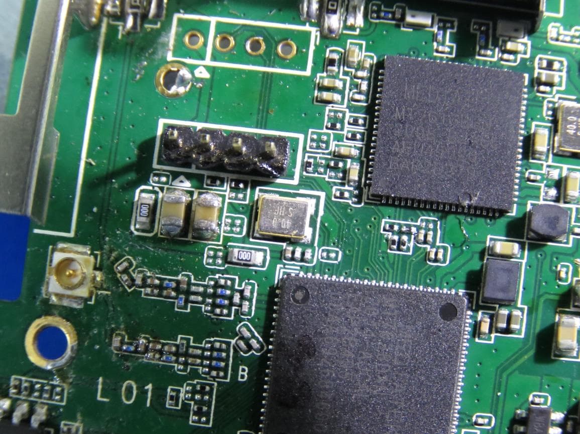
PANWA9563
Dec 17, 2020AC1200 FE Repeater
Equipment Class
NII - Unlicensed National Information Infrastructure TX