PANWL1205WLAN 11b USB Module
CC&C Technologies, Inc.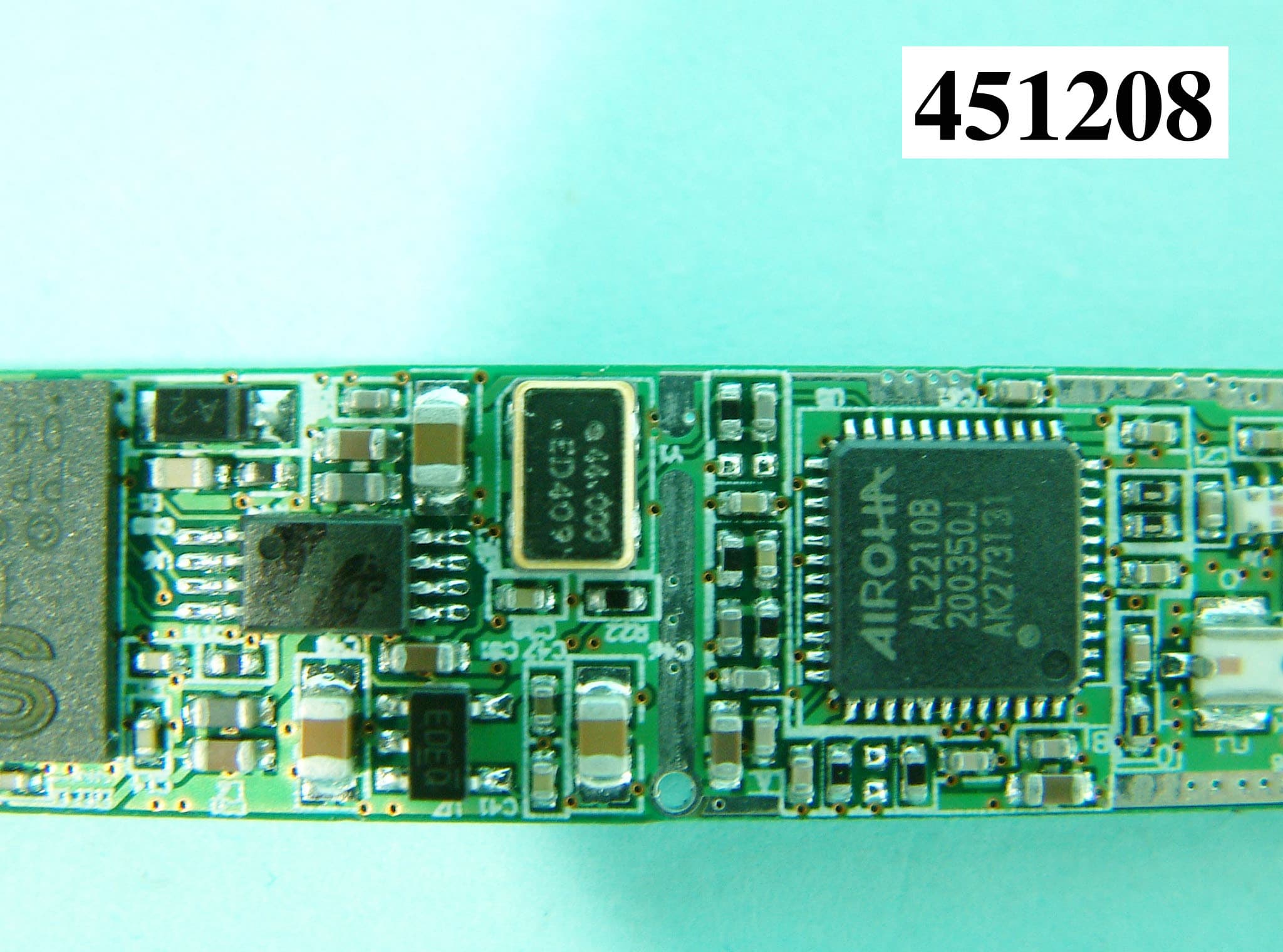
Click to zoom
Application Details
- Equipment Class
- DTS - Digital Transmission System
- Date of Grant
- May 31, 2004
- Application Purpose
- Original Equipment
- Date of Application
- May 31, 2004
- Equipment Note
- WLAN 11b USB Module
- Frequency Range
- 2412.00000000 - 2462.00000000
- Company
- CC&C Technologies, Inc.
- Country
- Taiwan
Documents & Files
Document Text
Text extracted from the exhibit documents filed with the FCC. Open a document above to read the original.
Users Manual
8F, 150, Jian Yi Road, Chung Ho City, Taipei County, Taiwan 235, R.O.C. TEL: 886-2-8226-5088 FAX: 886-2-8226-5077 User’s Manual WLAN 11b USB Module 12*71 WL-1205 Version1.2 2004/05/27 Technologies, Inc. 2 Table of Contents Information to User...................................... 3 1 Introduction................................................ 5 2 Wireless LAN basics.................................... 6 3 Windows Installation.................................... 7 3.1 Install Driver/Utility...................................... 8 3.2 Configuration Utility................................................. 10 3.2.1 Configured at “Windows XP configuration”........ 10 3.2.2 Configured at “Advanced configuration”....... 11 4 Technical Specifications of WLAN 11b USB Module 12*71 ... 15 Troubleshooting.......................................... 17 Glossary................................................... 18 Product names mentioned herein may be trademarks and/or registered trademarks of their respective companies. 3 INFORMATION TO USER Federal Communication Commission Interference Statement This equipment has been tested and found to comply with the limits for a Class B digital device, pursuant to Part 15 of the FCC Rules. These limits are designed to provide reasonable protection against harmful interference in a residential installation. This equipment generates, uses and can radiate radio frequency energy and, if not installed and used in accordance with the instructions, may cause harmful interference to radio communications. However, there is no guarantee that interference will not occur in a particular installation. If this equipment does cause harmful interference to radio or television reception, which can be determined by turning the equipment off and on, the user is encouraged to try to correct the interference by one of the following measures: -Reorient or relocate the receiving antenna. -Increase the separation between the equipment and receiver. -Connect the equipment into an outlet on a circuit different from that to which the receiver is connected. -Consult the dealer or an experienced radio/TV technician for help. This device complies with Part 15 of the FCC Rules. Operation is subject to the following two conditions: (1) This device may not cause harmful interference, and (2) this device must accept any interference received, including interference that may cause undesired operation. FCC Caution: Any changes or modifications not expressly approved by the party responsible for compliance could void the user's authority to operate this equipment. IMPORTANT NOTE: FCC Radiation Exposure Statement: This equipment complies with FCC radiation exposure limits set forth for an uncontrolled environment. This transmitter must not be co-located or operating in conjunction with any other antenna or transmitter. 4 This device is intended only for OEM integrators under the following conditions: The transmitter module may not be co-located with any other transmitter or antenna. As long as conduction above is met, further transmitter test will not be required. However, the OEM integrator is still responsible for testing their end-product for any additional compliance requirements required with this module installed (for example, digital device emissions, PC peripheral requirements, etc.). IMPORTANT NOTE: In the event that these conditions can not be met (for example certain laptop configurations or co-location with another transmitter), then the FCC authorization is no longer considered valid and the FCC ID can not be used on the final product. In these circumstances, the OEM integrator will be responsible for re-evaluating the end product (including the transmitter) and obtaining a separate FCC authorization. End Product Labeling The final end product must be labeled in a visible area with the following: “Contains TX FCC ID: PANWL1205”. Manual Information That Must be Included The OEM integrator has to be aware not to provide information to the end user regarding how to install or remove this RF module in the users manual of the end product which integrate this module. IMPORTANT NOTE: To comply with FCC RF exposure compliance requirements. The antenna must not be co-located or operating in conjunction with any other antenna or transmitter. 5 REGULATORY INFORMATION WLAN 11b USB Module 12*71 must be installed and used in strict accordance with the instructions. This device complies with the following radio frequency and safety standards. USA - Federal Communications Commission (FCC) This device complies with Part 15 of FCC Rules. The channel identifiers, channel center frequencies, and regulatory domains of each 22-MHz-wide channel are shown in following Table. Regulatory Domains Channel Identifier Center Frequency (MHZ) Japan ETSI North America Israel France Mexico 1 2412 ˇ ˇ ˇ 2 2417 ˇ ˇ ˇ 3 2422 ˇ ˇ ˇ ˇ 4 2427 ˇ ˇ ˇ ˇ 5 2432 ˇ ˇ ˇ ˇ 6 2437 ˇ ˇ ˇ ˇ 7 2442 ˇ ˇ ˇ ˇ 8 2447 ˇ ˇ ˇ ˇ 9 2452 ˇ ˇ ˇ ˇ 10 2457 ˇ ˇ ˇ ˇ ˇ 11 2462 ˇ ˇ ˇ ˇ ˇ 12 2467 ˇ ˇ ˇ 13 2472 ˇ ˇ ˇ 14 2484 ˇ 6 1. Introduction Thank you for purchasing Wireless Local Area Net (WLAN) 11b USB Module 12*71. You are about to install a networking system that is not only fast and powerful, but also easy to set up and simple to maintain. In a short time you and those in your network will be able to share a local printer and files, access the Internet, and roam about the office wire-free. Using radio frequency (RF) technology, WLANs transmit and receive data over the air, minimizing the need for wired connections. Thus, WLANs combine data connectivity with user mobility, and, through simplified configuration, enable movable LANs. This wireless networking solution has been designed for both large and small businesses, and it is scalable so that you can easily add more users and new network features as your business grows. This manual will assist you in the installing WLAN 11b USB Module 12*71. 7 2. Wireless LAN basics Wireless LAN network defined …
Text truncated - open the document above for the full version.
Cover Letter(s)
Request Letter Subject: Limited Module Approval Date: 31 th May 2004 FCC ID: PANWL1205 Dear Reviewer, We, Sporton International Inc., are authorized by CC&C Technologies, Inc. to have their state-of-the-art WLAN 11b USB Module 12x71 approved under limited module approval authorization specific the notebook computer. This module is going to be integrated inside the notebook, and the interface of this module is USB. The requirements defined in Public Notice DA00-1407 have been fulfilled and clearly explained below. 1. The requirement of RF shielding: The shielding of the radio portion can be demonstrated in exhibition External Photo. 2. The requirement of buffered inputs: Buffered data inputs stage has been integrated in chip SiS-162. 3. The requirement of power supply regulation: The part number of the power regulator is APL5509-33DC and RT9167_3.3V. 4. The requirements of section 15.203 and 15.204(C): The requirements of antenna connector and spurious emission have been fulfilled. Please reference the Test Report. 5. The requirement of stand-alone test configuration: Please reference exhibition Test Configuration Photo for the stand-alone test configuration. 6. The requirement of labeling: The instruction on the labeling rule of the end product has been stated in the users manual of this module. Please also see the exhibition Label Sample. 7. The requirement of compliance on specific rule or operating requirements: The required FCC rule has been fulfilled and all the instructions for maintaining compliance has been clearly stated in the Users Manual. 8. The requirement of RF exposure: This module is specific to the notebook computer and with output power which is lower than the low threshold, so no SAR testing is required. Instead of SAR, MPE calculation is attached in the test report as reference. Please do not hesitate to contact me for any questions of this request letter. Thank you. Regards,
Cover Letter(s)
American Telecommunications Certification Body Inc. 6731 Whittier Ave, McLean, VA 22101 June 1, 2004 RE: CC&C Technologies, Inc. FCC ID: PANWL1205 After a review of the submitted information, I have a few comments on the above referenced Application. Administrative Issues: 1) FYI....The FCC logo is not necessary on the labeling and should be removed since this device is not a self contained PC peripheral sold to the end user. Technical Issues: 2) It can not adequately be determined how the device was positioned on the table from the photographs provided. Per February 04, TCB training states, DO NOT LAY ANTENAS ON WOOD TABLETOP, and Antenna positioning in test setup should represent typical final-product configuration. The antenna should not be placed directly on the wooden table top but positioned above the table top in a fashion typical of final use. Please provide further information or retest if necessary. 3) The FCC expects the device to be tested for radiated emissions to 10 th harmonic of the highest fundamental frequency. From the plots it appear that only up to 5 GHz was scanned. Please review. 4) Please provide a separate RF exposure exhibit for this device. (see attached example). Note that the 60/f should be based on the center of the band of TX. Also, the RF exposure information given in the test report assumes 20 cm, which is not relevant. Please correct. 5) Please explain why the fundamental frequencies do not appear in the Radiated plots. Timothy R. Johnson Examining Engineer mailto: [email protected] The items indicated above must be submitted before processing can continue on the above referenced application. Failure to provide the requested information may result in application termination. Correspondence should be considered part of the permanent submission and may be viewed from the Internet after a Grant of Equipment Authorization is issued. Please do not respond to this correspondence using the email reply button. In order for your response to be processed expeditiously, you must submit your documents through the AmericanTCB.com website. Also, please note that partial responses increase processing time and should not be submitted. Any questions about the content of this correspondence should be directed to the sender.
Cover Letter(s)
Response for CC&C 1. ok. 2. Please see attached test result comparison. 3. We have searched the frequency range up to 25GHz 4. Yes, I have asked Linda re-submit RF exposure exhibition to your web site. 5. Our first test for the product is the carrier power strength which will be used on the bandedge emission. Then we will connect the Notch filter and amplifer for the spurious in case the amplifer being saturated. That is why we will have no carrier frequency on the plot.
External Photos
REPORT NO. : F452108 SPORTON International Inc. PAGE NUMBER : A1 OF A1 TEL : 886-2-2696-2468 ISSUED DATE : May 31, 2004 FAX : 886-2-2696-2255 APPENDIX A. Photographs of EUT 452108 452108 REPORT NO. : F452108 SPORTON International Inc. PAGE NUMBER : A2 OF A2 TEL : 886-2-2696-2468 ISSUED DATE : May 31, 2004 FAX : 886-2-2696-2255 452108 452108 REPORT NO. : F452108 SPORTON International Inc. PAGE NUMBER : A3 OF A3 TEL : 886-2-2696-2468 ISSUED DATE : May 31, 2004 FAX : 886-2-2696-2255 452108
ID Label/Location Info
WLAN 11b USB Module 12*71 (WL-1205) Lable Location & Lable
Internal Photos
REPORT NO. : F452108 SPORTON International Inc. PAGE NUMBER : A1 OF A1 TEL : 886-2-2696-2468 ISSUED DATE : May 31, 2004 FAX : 886-2-2696-2255 APPENDIX A. Photographs of EUT 452108 452108 REPORT NO. : F452108 SPORTON International Inc. PAGE NUMBER : A2 OF A2 TEL : 886-2-2696-2468 ISSUED DATE : May 31, 2004 FAX : 886-2-2696-2255 452108 452108 REPORT NO. : F452108 SPORTON International Inc. PAGE NUMBER : A3 OF A3 TEL : 886-2-2696-2468 ISSUED DATE : May 31, 2004 FAX : 886-2-2696-2255 452108
Operational Description
FCC ID:PANWL1205 Description of Operational The transmitter of the EUT is powered by host equipment. The antenna used in this product is Chip antenna without antenna connector. The other instruction, please have a look at the users manual. DSSS Information This device is Direct Sequence Spread Spectrum; the data is mixed by pseudorandom code, which is an orthogonal code. The mixed data is digital modulated by BPSK and QPSK technique depends on the data rates. The CCK coding is applied for increasing the data rate, and also the processing gain will be increased. The bit rates are 1,2,5.5,11Mbps, the symbol rates are1,1,1.375,1.375Mbps, the chip rates are always 11Mbps. So, the Chip/symbol is 11,11,8 and 8 respectively. Although is higher bit rate, the processing gain is lower than 10, but the CCK coding used in higher bit rate will provide 2.2dB coding gain.
RF Exposure Info
FCC ID: PANWL1205 RF Exposure Application of the filed product This product is a 802.11b module with on board chip antenna produced by CC&C Technologies, Inc. It is designed to be integrated inside the notebook computer. It should be classified as an limited portable module. RF Exposure Evaluation The power threshold for SAR evaluation is 60mW/f, where f = 2.45GHz in this case. So, the threshold should be 13.8dBm. The antenna gain of this module is 0dBi, and the conducted output power is 13.5dBm. So, no SAR evaluation is required.
Test Report
FCC ID: PANWL1205 Issued on May 31, 2004 Report No.: F452108 SPORTON International Inc. TEL : 886-2-2696-2468 FAX : 886-2-2696-2255 FCC TEST REPORT CATEGORY : Limited Module Approval PRODUCT NAME : WLAN 11b USB module 12×71 FCC ID. : PANWL1205 FILING TYPE : Certification BRAND NAME : CC&C MODEL NAME : WL-1205 APPLICANT : CC&C Technologies, Inc. 8F, 150, Jian Yi Road, Chung Ho City, Taipei County, Taiwan, 2354, R.O.C. MANUFACTURER : Same as Applicant ISSUED BY : SPORTON INTERNATIONAL INC. 6F, No. 106, Sec. 1, Hsin Tai Wu Rd., His Chih, Taipei Hsien, Taiwan, R.O.C. Statements: The test result in this report refers exclusively to the presented test model / sample. Without written approval of SPORTON International Inc., the test report shall not be reproduced except in full. Certificate or Test Report could not be used by the applicant to claim the product endorsement by CNLA, NVLAP or any agency of U.S. government. The test equipment used to perform the test are calibrated and traceable to NML/ROC or NIST/USA. Dr. Alan Lane Vice General Manager Sporton International Inc. Lab Code: 200079-0 1190 ILAC MRA FCC ID: PANWL1205 Issued on May 31, 2004 Report No.: F452108 SPORTON International Inc. FCC ID. : PANWL1205 TEL : 886-2-2696-2468 Page No. : i FAX : 886-2-2696-2255 Issued Date : May 31, 2004 Table of Contents History of this test report....................................................................................................................................ii 1. General Description of Equipment under Test.............................................................................................1 1.1. Applicant..........................................................................................................................................................................................1 1.2. Manufacturer ...................................................................................................................................................................................1 1.3. Basic Description of Equipment under Test ....................................................................................................................................1 1.4. Features of Equipment under Test..................................................................................................................................................1 1.5. Table for Carrier Frequencies .........................................................................................................................................................2 2. Test Configuration of the Equipment under Test.........................................................................................3 2.1. Description of the Test ....................................................................................................................................................................3 2.2. Frequency Range Investigated .......................................................................................................................................................3 2.3. Description of Test Supporting Units...............................................................................................................................................4 2.4. Connection Diagram of Test System ..............................................................................................................................................5 2.5. Test Software ..................................................................................................................................................................................6 3. Test Location and Standards .........................................................................................................................7 3.1. Test Location...................................................................................................................................................................................7 3.2. Test Conditions ...............................................................................................................................................................................7 3.3. Standards for Methods of Measurement .........................................................................................................................................7 3.4. DoC Statement................................................................................................................................................................................7 4. List of Measurements......................................................................................................................................8 4.1. Summary of the Test Results ..........................................................................................................................................................8 5. Test Result .......................................................................................................................................................9 5.1. Test of 6dB Spectrum Bandwidth ( DSSS System ) .......................................................................................................................9 5.2. Test of Maximum Peak Output Power ..........................................................................................................................................12 5.3. Test of Peak Power Spectral Density............................................................................................................................................13 5.4. Test of Band Edges Emission .......................................................................................................................................................16 5.5. Test of AC Power Line Conducted Emission .............................................................................................................…
Text truncated - open the document above for the full version.
Test Report
0 cm separation 2cm separation
Test Setup Photos
FCC ID: PANWL1205 Issued on May 31, 2004 Report No.: F452108 SPORTON International Inc. FCC ID. : PANWL1205 TEL : 886-2-2696-2468 Page No. : 22of 47 FAX : 886-2-2696-2255 Issued Date : May 31, 2004 5.5.4 Photographs of Conducted Emission Test Configuration z The photographs show the configuration that generates the maximum emission. FRONT VIEW REAR VIEW FCC ID: PANWL1205 Issued on May 31, 2004 Report No.: F452108 SPORTON International Inc. FCC ID. : PANWL1205 TEL : 886-2-2696-2468 Page No. : 23of 47 FAX : 886-2-2696-2255 Issued Date : May 31, 2004 SIDE VIEW FCC ID: PANWL1205 Issued on May 31, 2004 Report No.: F452108 SPORTON International Inc. FCC ID. : PANWL1205 TEL : 886-2-2696-2468 Page No. : 42of 47 FAX : 886-2-2696-2255 Issued Date : May 31, 2004 5.6.5 Photographs of Radiated Emission Test Configuration z The photographs show the configuration that generates the maximum emission. FRONT VIEW REAR VIEW
Contact Information
Applicant
Cooper Hou(Product Manager)
Technical Contact
Sporton International Inc.Alan Lane
[email protected]886-3-327-3456
No.52, Hwa-Ya 1st Rd. · Taoyuan · Taiwan
Non-Technical Contact
Sporton International Inc.Alan Lane
[email protected]886-3-327-3456
Test Firm
Sporton International Inc.W Huang
Technical Specifications
| # | Rule Parts | Frequency Range | Power Output |
|---|---|---|---|
| 1 | 15C | 2.41 GHz - 2.46 GHz | 22.00 mW |
Other Applications from CC&C Technologies, Inc.
PANBM3095
Jun 24, 2026Bluetooth v5.4 APTX LE Audio RX Module
Equipment Class
DSS - Part 15 Spread Spectrum Transmitter
PANBA550T
Sep 26, 2024Triple source to BT5.3 LE Audio Transmitter
Equipment Class
DSS - Part 15 Spread Spectrum Transmitter
PANBA55T
Sep 26, 2024Dual source to BT5.3 LE Audio Transmitter
Equipment Class
DTS - Digital Transmission System
PANBA300M
Dec 08, 2022BT5 Aptx Audio Mixer
Equipment Class
DTS - Digital Transmission System
PANWA9563
Dec 17, 2020AC1200 FE Repeater
Equipment Class
NII - Unlicensed National Information Infrastructure TX