PANWL1302802.11b Wireless Access Point
CC&C Technologies, Inc.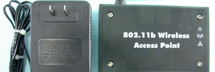
Click to zoom
Application Details
- Equipment Class
- DTS - Digital Transmission System
- Date of Grant
- Nov 16, 2003
- Application Purpose
- Original Equipment
- Date of Application
- Nov 16, 2003
- Equipment Note
- 802.11b Wireless Access Point
- Frequency Range
- 2412.00000000 - 2462.00000000
- Company
- CC&C Technologies, Inc.
- Country
- Taiwan
Documents & Files
Document Text
Text extracted from the exhibit documents filed with the FCC. Open a document above to read the original.
Users Manual
User’s Manual Version: 2.1 Wireless LAN Access Point Trademarks Copyright @2003 Contents are subject to change without notice. All trademarks belong to their respective proprietors. Copyright Statement THIS DOCUMENT CONTAINS OF PROPRIETARY TECHNICAL INFORMATION THAT IS THE PROPERTY OF THIS COMPANY. AND NO PART OF THIS DOCUMENTATION MAY BE REPRODUCED, STORED IN A RETRIEVAL SYSTEM OR TRANSMITTED IN ANY FORM OR BY ANY MEANS, ELECTRICAL OR MECHANICAL, BY PHOTOCOPYING, RECORDING, OR OTHERWISE, WITHOUT THE PRIOR WRITTEN CONSENT OF THIS COMPANY. USER’S MANUAL OF WLAN ACCESS POINT Version: 2.1 i Revision History DATE REVISION 2003/7/14 First release 2003/7/22 Release 1.1; add information about time required on boot-up sequence. 2003/7/24 Release 1.2; modify the boot-up sequence notice in chapter 1 2003/8/4 Release 2.0; add configuration examples 2003/9/9 Release 2.1; modify power supply to DC 7.5V USER’S MANUAL OF WLAN ACCESS POINT Version: 2.1 ii Terminology ANSI American National Standards Institute AP Access Point CCK Complementary Code Keying CSMA/CA Carrier Sense Multiple Access/ Collision Avoidance CSMA/CD Carrier Sense Multiple Access/ Collision Detection DHCP Dynamic Host Configuration Protocol DSSS Direct Sequence Spread Spectrum FCC Federal Communications Commission FTP File Transfer Protocol IEEE Institute of Electrical and Electronic Engineers IP Internet Protocol ISM Industrial, Scientific and Medical LAN Local Area Network MAC Media Access Control NAT Network Address Translation NT Network Termination PSD Power Spectral Density RF Radio Frequency SNR Signal to Noise Ratio SSID Service Set Identification TCP Transmission Control Protocol TFTP Trivial File Transfer Protocol WEP Wired Equivalent Privacy WLAN Wireless Local Area Network USER’S MANUAL OF WLAN ACCESS POINT Version: 2.1 iii Table of Contents REVISION HISTORY .....................................................................................................................I TERMINOLOGY ........................................................................................................................... II 1 INTRODUCTION....................................................................................................................1 1.1 PACKAGE CONTENTS........................................................................................................... 1 1.2 PRODUCT SPECIFICATIONS.................................................................................................. 1 1.3 PRODUCT FEATURES........................................................................................................... 2 1.4 TOP PANEL DESCRIPTION.................................................................................................... 2 1.5 REAR PANEL DESCRIPTION.................................................................................................. 3 2 INSTALLATION ..................................................................................................................... 4 2.1 HARDWARE INSTALLATION................................................................................................. 4 2.2 SOFTWARE INSTALLATION................................................................................................... 4 3 SOFTWARE CONFIGURATION ......................................................................................... 5 3.1 PREPARE YOUR PC TO CONFIGURE THE WIRELESS LAN ACCESS POINT............................. 5 3.2 CONNECT TO THE WIRELESS LAN ACCESS POINT.............................................................. 7 3.3 MANAGEMENT AND CONFIGURATION ON THE WIRELESS LAN ACCESS POINT.................... 7 3.3.1 S TAT U S............................................................................................................................ 7 3.3.2 WIRELESS BASIC SETTINGS............................................................................................ 8 3.3.3 WIRELESS ADVANCED SETTINGS.................................................................................... 9 3.3.4 WIRELESS SECURITY SETUP.......................................................................................... 11 3.3.5 WIRELESS ACCESS CONTROL........................................................................................ 12 3.3.6 LAN INTERFACE SETUP................................................................................................ 14 3.3.7 S TAT I S T I C S.................................................................................................................... 15 3.3.8 UPGRADE FIRMWARE.................................................................................................... 16 3.3.9 SAV E /RELOAD SETTINGS.............................................................................................. 17 3.3.10 PASSWORD SETUP......................................................................................................... 17 4 FREQUENTLY ASKED QUESTIONS (FAQ).................................................................... 19 4.1 W HAT AND HOW TO FIND MY PC’S IP AND MAC ADDRESS? ............................................. 19 4.2 WHAT IS WIRELESS LAN? ................................................................................................ 19 4.3 WHAT ARE ISM BANDS? ................................................................................................... 19 4.4 H OW DOES WIRELESS NETWORKING WORK?...................................................................... 19 USER’S MANUAL OF WLAN ACCESS POINT Version: 2.1 iv 4.5 WHAT IS BSSID? .............................................................................................................. 20 4.6 WHAT IS ESSID? .............................................................................................................. 20 4.7 WHAT ARE POTENTIAL FACTORS THAT MAY CAUSES INTERFERENCE? ................................ 21 4.8 WHAT ARE THE OPEN SYSTEM AND SHARED KEY AUTHE…
Text truncated - open the document above for the full version.
Cover Letter(s)
American Telecommunications Certification Body Inc. 6731 Whittier Ave, McLean, VA 22101 November 10, 2003 RE: CC&C Technologies, Inc. FCC ID: PANWL1302 I have a few comments on the above referenced Application. 1) The 2 part statement provided on the label contains a misspelled word. The word shown as "undesured" should be "undesired". Please provide an updated label. 2) Will all the "copper tape" seen in the internal photographs be integrated into all production models? The modifications made do not appear to be a solution usable in production. Note that copper tape is considered by most to be a temporary fix. Due to the nature of the modifications, it is recommended that if the manufacturer provide a production level modified sample and all testing be performed on this sample. Please comment. 3) For the bandedge test, the marker should be placed on the highest emission falling in the restricted band. This does not appear to have been done for the low band side. Timothy R. Johnson Examining Engineer mailto: [email protected] The items indicated above must be submitted before processing can continue on the above referenced application. Failure to provide the requested information may result in application termination. Correspondence should be considered part of the permanent submission and may be viewed from the Internet after a Grant of Equipment Authorization is issued. Please do not respond to this correspondence using the email reply button. In order for your response to be processed expeditiously, you must submit your documents through the AmericanTCB.com website. Also, please note that partial responses increase processing time and should not be submitted. Any questions about the content of this correspondence should be directed to the sender.
External Photos
Page 1 CONSTRUCTION PHOTOS OF EUT Page 2 Page 3 Page 4 Page 5
ID Label/Location Info
Page 1 Label location
Internal Photos
Page 1 CONSTRUCTION PHOTOS OF EUT Page 2 Page 3 Page 4 Page 5 Page 6 Page 7
Operational Description
FCC ID: PANWL1302 Report No. RF920916R02 Operational Description The transmitter of the EUT is powered by power adapter. The antenna used in this product is diople antenna without antenna connector. Under normal use condition, the user has to keep at least 20 cm separation distance between radiator and the body of the user. The other instruction, please have a look at the users manual. DSSS Information This device is Direct Sequence Spread Spectrum, the data is mixed by pseudorandom code which is an orthogonal code. The mixed data is digital modulated by BPSK and QPSK technique depends on the data rates. The CCK coding is applied for increasing the data rate, and also the processing gain will be increased. The bit rates are 1,2,5.5,11Mbps, the symbol rates are 1,1,1.375,1.375Mbps, the chip rates are always 11Mbps. So, the Chip/symbol is 11,11,8 and 8 respectively. Although is higher bit rate, the processing gain is lower than 10, but the CCK coding used in higher bit rate will provide 2.2dB coding gain.
RF Exposure Info
FCC ID: PANWL1302 Report No: RF920916R02 1 FCC TEST REPORT REPORT NO.: RF920916R02 MODEL NO.: WL-1302 ACCORDING: FCC Guidelines for Human Exposure IEEE C95.1 APPLICANT: CC&C TECHNOLOGIES INC. ADDRESS: 8F, 150, Jian Yi Road, Chung Ho City, Taipei County, Taiwan 235, R.O.C. ISSUED BY: Advance Data Technology Corporation LAB LOCATION: 47 14th Lin, Chiapau Tsun, Linko, Taipei, Taiwan, R.O.C. 0528 ILAC MRA Lab Code: 200102-0 FCC ID: PANWL1302 Report No: RF920916R02 2 RF Exposure Measurement (Mobile Device) 1. Introduction In this document, we try to prove the safety of radiation harmfulness to the human body for our product. The limit for Maximum Permissible Exposure (MPE) specified in FCC 1.1310 is followed. The Gain of the antenna used in this product is measured in a Fully Anechoic Chamber (FAC) calibrated for antenna measurement in ADT, and also the maximum total power input to the antenna is measured. Through the Friis transmission formula and the maximum gain of the antenna, we can calculate the distance, away from the product, where the limit of MPE is reached. Although the Friis transmission formula is a far field assumption, the calculated result of that is an over-prediction for near field power density. We will take that as the worst case to specify the safety range. 2. RF Exposure Limit According to FCC 1.1310: The criteria listed in the following table shall be used to evaluate the environmental impact of human exposure to radio-frequency (RF) radiation as specified in 1.1307(b) LIMITS FOR MAXIMUM PERMISSIBLE EXPOSURE (MPE) Frequency Range (MHz) Electric Field Strength (V/m) Magnetic Field Strength (A/m) Power Density (mW/cm 2 ) Average Time (minutes) (A)Limits For Occupational / Control Exposures 300-1500......F/3006 1500-100,000......56 (B)Limits For General Population / Uncontrolled Exposure 300-1500......F/15006 1500-100,000......1.030 F = Frequency in MHz FCC ID: PANWL1302 Report No: RF920916R02 3 3. Friis Formula Friis transmission formula: Pd = (Pout*G) / (4*pi*r 2 ) where Pd = power density in mW/cm 2 Pout = output power to antenna in mW G = gain of antenna in linear scale Pi = 3.1416 R = distance between observation point and center of the radiator in cm If we know the maximum Gain of the antenna and the total power input to the antenna, through the calculation, we will know the MPE value at distance 20cm. Ref.: David K. Cheng, Field and Wave Electromagnetics, Second Edition, Page 640, Eq. (11-133). 4 EUT Operating condition The software provided by Manufacturer enabled the EUT to transmit and receive data at lowest, middle and highest channel individually. 5. Classification This device is not fixed inside the host equipment, for normal use, it is easy to be re- located in the place where at least 20cm far away from the body of the user. Warning statement to the user for keeping at least 20cm or more separation distance with the antenna should be included in users manual. So, this device is classified as Mobile Device. FCC ID: PANWL1302 Report No: RF920916R02 4 6 Test Results 6.1 Antenna Gain The maximum Gain measured in Fully Anechoic Chamber is 2dBi or 1.584 (numeric). 6.2 Output Power Into Antenna & MPE value at distance 20cm: Channel Channel Frequency (MHz) Output Power to Antenna (mW) Power Density (mW/cm 2 ) Limit of Power Density (mW/cm 2 ) 1241248.0840.0151.0 6243746.3450.0151.0 11246244.6680.0141.0
Test Report
FCC ID: PANWL1302 Report No.: RF920916R021Issued: October 15, 2003 FCC TEST REPORT REPORT NO.: RF920916R02 MODEL NO.: WL-1302 RECEIVED: September 16, 2003 TESTED: October 08, 2003 ~ October 09, 2003 APPLICANT: CC&C TECHNOLOGIES, INC. ADDRESS: 8F, 150, Jian Yi Road, Chung Ho City, Taipei County, Taiwan 235, R.O.C. ISSUED BY: Advance Data Technology Corporation LAB LOCATION: 47 14th Lin, Chiapau Tsun, Linko, Taipei, Taiwan, R.O.C. This test report consists of 50 pages in total. It may be duplicated completely for legal use with the approval of the applicant. It should not be reproduced except in full, without the written approval of our laboratory. The client should not use it to claim product endorsement by CNLA, NVLAP or any government agencies. The test results in the report only apply to the tested sample. 0528 ILAC MRA Lab Code: 200102-0 FCC ID: PANWL1302 Report No.: RF920916R022Issued: October 15, 2003 Table of Contents 1CERTIFICATION .......................................................................................... 4 2SUMMARY OF TEST RESULTS .................................................................. 5 3GENERAL INFORMATION........................................................................... 6 3.1 GENERAL DESCRIPTION OF EUT ............................................................ 6 3.2 DESCRIPTION OF TEST MODES .............................................................. 7 3.3 GENERAL DESCRIPTION OF APPLIED STANDARDS .............................. 7 3.4 DESCRIPTION OF SUPPORT UNITS......................................................... 8 3.5 CONFIGURATION OF SYSTEM UNDER TEST ......................................... 9 4TEST TYPES AND RESULTS .................................................................... 10 4.1 CONDUCTED EMISSION MEASUREMENT............................................. 10 4.1.1LIMITS OF CONDUCTED EMISSION MEASUREMENT ........................... 10 4.1.2TEST INSTRUMENTS ............................................................................... 10 4.1.3TEST PROCEDURES .................................................................................11 4.1.4DEVIATION FROM TEST STANDARD .......................................................11 4.1.5TEST SETUP ............................................................................................. 12 4.1.6EUT OPERATING CONDITIONS ............................................................... 12 4.1.7TEST RESULTS ......................................................................................... 13 4.2 RADIATED EMISSION MEASUREMENT.................................................. 19 4.2.1 LIMITS OF RADIATED EMISSION MEASUREMENT ................................ 19 4.2.2TEST INSTRUMENTS ............................................................................... 20 4.2.3TEST PROCEDURES ................................................................................ 21 4.2.4DEVIATION FROM TEST STANDARD ...................................................... 21 4.2.5TEST SETUP ............................................................................................. 22 4.2.6EUT OPERATING CONDITIONS ............................................................... 22 4.2.7TEST RESULTS ......................................................................................... 23 4.3 6dB BANDWIDTH MEASUREMENT ......................................................... 28 4.3.1 LIMITS OF 6dB BANDWIDTH MEASUREMENT ....................................... 28 4.3.2TEST INSTRUMENTS ............................................................................... 28 4.3.3TEST PROCEDURE .................................................................................. 28 4.3.4DEVIATION FROM TEST STANDARD ...................................................... 28 4.3.5TEST SETUP ............................................................................................. 29 FCC ID: PANWL1302 Report No.: RF920916R023Issued: October 15, 2003 4.3.6EUT OPERATING CONDITIONS ............................................................... 29 4.3.7TEST RESULTS ......................................................................................... 30 4.4MAXIMUM PEAK OUTPUT POWER ......................................................... 34 4.4.1LIMITS OF MAXIMUM PEAK OUTPUT POWER MEASUREMENT .......... 34 4.4.2TEST INSTRUMENTS ............................................................................... 34 4.4.3TEST PROCEDURES ................................................................................ 35 4.4.4DEVIATION FROM TEST STANDARD ...................................................... 35 4.4.5TEST SETUP ............................................................................................. 35 4.4.6EUT OPERATING CONDITIONS ............................................................... 35 4.4.7TEST RESULTS ......................................................................................... 36 4.5 POWER SPECTRAL DENSITY MEASUREMENT .................................... 37 4.5.1LIMITS OF POWER SPECTRAL DENSITY MEASUREMENT................... 37 4.5.2TEST INSTRUMENTS ............................................................................... 37 4.5.3TEST PROCEDURE .................................................................................. 38 4.5.4DEVIATION FROM TEST STANDARD ...................................................... 38 4.5.5TEST SETUP ............................................................................................. 38 4.5.6EUT OPERATING CONDITIONS ............................................................... 38 4.5.7TEST RESULTS ......................................................................................... 39 4.6BAND EDGES MEASUREMENT ............................................................... 43 4.6.1LIMITS OF BAND EDGES MEASUREMENT............................................. 43 4.6.2TEST INSTRUMENTS ..........................…
Text truncated - open the document above for the full version.
Test Setup Photos
FCC ID: PANWL1302 Report No.: RF920916R0248Issued: October 15, 2003 5 PHOTOGRAPHS OF THE TEST CONFIGURATION CONDUCTED EMISSION TEST FCC ID: PANWL1302 Report No.: RF920916R0249Issued: October 15, 2003 RADIATED EMISSION TEST
Contact Information
Applicant
Cooper Hou(Product Manager)
Technical Contact
Advance Data Technology CorporationEllis Wu
[email protected]+886-3-327-0910
13-1, Lane 19, WenShan 3rd., St. · Taoyuan · Taiwan
Non-Technical Contact
Advance Data Technology CorporationEllis Wu
[email protected]+886-3-327-0910
Test Firm
Bureau Veritas CPS (H.K.) Ltd. Taoyuan BranchTommy Wu
Technical Specifications
| # | Rule Parts | Frequency Range | Power Output |
|---|---|---|---|
| 1 | 15C | 2.41 GHz - 2.46 GHz | 48.00 mW |
Other Applications from CC&C Technologies, Inc.
PANBM3095
Jun 24, 2026Bluetooth v5.4 APTX LE Audio RX Module
Equipment Class
DSS - Part 15 Spread Spectrum Transmitter
PANBA550T
Sep 26, 2024Triple source to BT5.3 LE Audio Transmitter
Equipment Class
DSS - Part 15 Spread Spectrum Transmitter
PANBA55T
Sep 26, 2024Dual source to BT5.3 LE Audio Transmitter
Equipment Class
DTS - Digital Transmission System
PANBA300M
Dec 08, 2022BT5 Aptx Audio Mixer
Equipment Class
DTS - Digital Transmission System
PANWA9563
Dec 17, 2020AC1200 FE Repeater
Equipment Class
NII - Unlicensed National Information Infrastructure TX