PANWL1502802.11b WLAN Router
CC&C Technologies, Inc.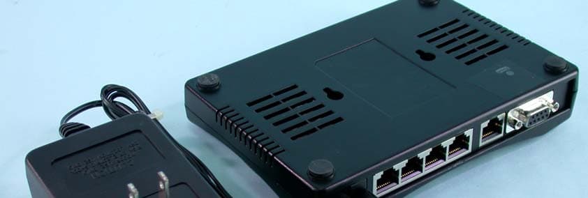
Click to zoom
Application Details
- Equipment Class
- DTS - Digital Transmission System
- Date of Grant
- Sep 23, 2003
- Application Purpose
- Original Equipment
- Date of Application
- Sep 23, 2003
- Equipment Note
- 802.11b WLAN Router
- Frequency Range
- 2412.00000000 - 2462.00000000
- Company
- CC&C Technologies, Inc.
- Country
- Taiwan
Documents & Files
Document Text
Text extracted from the exhibit documents filed with the FCC. Open a document above to read the original.
Users Manual
User’s Manual Version: 2.2 Wireless LAN Broadband Router Trademarks Copyright @2003 Contents are subject to change without notice. All trademarks belong to their respective proprietors. Copyright Statement THIS DOCUMENT CONTAINS OF PROPRIETARY TECHNICAL INFORMATION THAT IS THE PROPERTY OF THIS COMPANY. AND NO PART OF THIS DOCUMENTATION MAY BE REPRODUCED, STORED IN A RETRIEVAL SYSTEM OR TRANSMITTED IN ANY FORM OR BY ANY MEANS, ELECTRICAL OR MECHANICAL, BY PHOTOCOPYING, RECORDING, OR OTHERWISE, WITHOUT THE PRIOR WRITTEN CONSENT OF THIS COMPANY. Federal Communication Commission Interference Statement This equipment has been tested and found to comply with the limits for a Class B digital device, pursuant to Part 15 of the FCC Rules. These limits are designed to provide reasonable protection against harmful interference in a residential installation. This equipment generates, uses and can radiate radio frequency energy and, if not installed and used in accordance with the instructions, may cause harmful interference to radio communications. However, there is no guarantee that interference will not occur in a particular installation. If this equipment does cause harmful interference to radio or television reception, which can be determined by turning the equipment off and on, the user is encouraged to try to correct the interference by one of the following measures: - Reorient or relocate the receiving antenna. - Increase the separation between the equipment and receiver. - Connect the equipment into an outlet on a circuit different from that to which the receiver is connected. - Consult the dealer or an experienced radio/TV technician for help. This device complies with Part 15 of the FCC Rules. Operation is subject to the following two conditions: (1) This device may not cause harmful interference, and (2) this device must accept any interference received, including interference that may cause undesired operation. FCC Caution: Any changes or modifications not expressly approved by the party responsible for compliance could void the user's authority to operate this equipment. IMPORTANT NOTE: FCC Radiation Exposure Statement: This equipment complies with FCC radiation exposure limits set forth for an uncontrolled environment. This equipment should be installed and operated with minimum distance 20cm between the radiator & your body. This transmitter must not be co-located or operating in conjunction with any other antenna or transmitter. USER’S MANUAL OF WLAN BROADBAND ROUTER Version: 2.2 i Revision History DATE REVISION 2003/7/16 First release 2003/7/22 Release 1.1; add information about time required on boot-up sequence. 2003/7/24 Release 1.2; modify the boot-up sequence notice in chapter 1 2003/8/4 Release 2.0; add configuration examples 2003/9/5 Release 2.1; support multi-language including English, German and Spanish, change to DC v7.5 power supply 2003/9/17 Release 2.2; add FCC interference statement USER’S MANUAL OF WLAN BROADBAND ROUTER Version: 2.2 ii Terminology ANSI American National Standards Institute AP Access Point CCK Complementary Code Keying CSMA/CA Carrier Sense Multiple Access/ Collision Avoidance CSMA/CD Carrier Sense Multiple Access/ Collision Detection DHCP Dynamic Host Configuration Protocol DSSS Direct Sequence Spread Spectrum FCC Federal Communications Commission FTP File Transfer Protocol IEEE Institute of Electrical and Electronic Engineers IP Internet Protocol ISM Industrial, Scientific and Medical LAN Local Area Network MAC Media Access Control NAT Network Address Translation NT Network Termination PSD Power Spectral Density RF Radio Frequency SNR Signal to Noise Ratio SSID Service Set Identification TCP Transmission Control Protocol TFTP Trivial File Transfer Protocol WEP Wired Equivalent Privacy WLAN Wireless Local Area Network USER’S MANUAL OF WLAN BROADBAND ROUTER Version: 2.2 iii Table of Contents REVISION HISTORY .....................................................................................................................I TERMINOLOGY ........................................................................................................................... II 1 INTRODUCTION....................................................................................................................1 1.1 PACKAGE CONTENTS........................................................................................................... 1 1.2 PRODUCT SPECIFICATIONS.................................................................................................. 1 1.3 PRODUCT FEATURES........................................................................................................... 2 1.4 FRONT PANEL DESCRIPTION................................................................................................ 2 1.5 REAR PANEL DESCRIPTION.................................................................................................. 3 2 INSTALLATION ..................................................................................................................... 5 2.1 HARDWARE INSTALLATION................................................................................................. 5 2.2 SOFTWARE INSTALLATION................................................................................................... 5 3 SOFTWARE CONFIGURATION ......................................................................................... 6 3.1 PREPARE YOUR PC TO CONFIGURE THE WLAN BROADBAND ROUTER............................... 6 3.2 CONNECT TO THE WLAN BROADBAND ROUTER................................................................ 8 3.3 MANAGEMENT AND CONFIGURATION ON THE WLAN BROADBAND ROUTER..................... 8 3.3.1 S TAT U S............................................................................................................................ 8 3.3.2 WIRELESS BASIC SETTINGS.......................................................................................... 10 3…
Text truncated - open the document above for the full version.
Users Manual
USER’S MANUAL OF WLAN BROADBAND ROUTER Version: 2.2 18 Screenshot – WAN Interface Setup - 1 Screenshot – WAN Interface Setup - 2 Item Description Attain IP Automatically (DHCP) Click to select DHCP support on WAN interface for IP address assigned automatically from a DHCP server. USER’S MANUAL OF WLAN BROADBAND ROUTER Version: 2.2 19 Fixed IP Click to select fixed IP support on WAN interface. There are IP address, subnet mask and default gateway settings need to be done. IP Address If you select the fixed IP support on WAN interface, fill in the IP address for it. Subnet Mask If you select the fixed IP support on WAN interface, fill in the subnet mask for it. Default Gateway If you select the fixed IP support on WAN interface, fill in the default gateway for WAN interface out going data packets. PPPoE Click to select PPPoE support on WAN interface. There are user name, password, connection type and idle time settings need to be done. User Name If you select the PPPoE support on WAN interface, fill in the user name and password to login the PPPoE server. Password If you select the PPPoE support on WAN interface, fill in the user name and password to login the PPPoE server. Connection Type Select the connection type from pull-down menu. There are Continuous, Connect on Demand and Manual three types to select. Continuous connection type means to setup the connection through PPPoE protocol whenever this WLAN Broadband Router is powered on. Connect on Demand connection type means to setup the connection through PPPoE protocol whenever you send the data packets out through the WAN interface; there are a watchdog implemented to close the PPPoE connection while there are no data sent out longer than the idle time set. Manual connection type means to setup the connection through the PPPoE protocol by clicking the Connect button manually, and clicking the Disconnect button manually. Idle Time If you select the PPPoE and Connect on Demand connection type, fill in the idle time for auto-disconnect function. Value can be between 1 and 1000 minutes. Attain DNS Click to select getting DNS address for DHCP, PPPoE USER’S MANUAL OF WLAN BROADBAND ROUTER Version: 2.2 20 Automatically support. Please select Set DNS Manually if the Fixed IP support is selected. Set DNS Manually Click to select getting DNS address for Fixed IP support. DNS 1 Fill in the IP address of Domain Name Server 1. DNS 2 Fill in the IP address of Domain Name Server 2. DNS 3 Fill in the IP address of Domain Name Server 3. Apply Changes Click the Apply Changes button to complete the new configuration setting. Reset Click the Reset button to abort change and recover the previous configuration setting. 3.3.8 Firewall - Port Filtering Entries in this table are used to restrict certain types of data packets from your local network to Internet through the Gateway. Use of such filters can be helpful in securing or restricting your local network. Screenshot – Firewall - Port Filtering Item Description Enable Port Filtering Click to enable the port filtering security function. Port Range To restrict data transmission from the local network on USER’S MANUAL OF WLAN BROADBAND ROUTER Version: 2.2 21 Protocol Comments certain ports, fill in the range of start-port and end-port, and the protocol, also put your comments on it. The Protocol can be TCP, UDP or Both. Comments let you know about whys to restrict data from the ports. Apply Changes Click the Apply Changes button to register the ports to port filtering list. Reset Click the Reset button to abort change and recover the previous configuration setting. Delete Selected Click to delete the selected port range that will be removed from the port-filtering list. Delete All Click to delete all the registered entries from the port-filtering list. Reset Click the Reset button to abort change and recover the previous configuration setting. 3.3.9 Firewall - IP Filtering Entries in this table are used to restrict certain types of data packets from your local network to Internet through the Gateway. Use of such filters can be helpful in securing or restricting your local network. Screenshot – Firewall - IP Filtering USER’S MANUAL OF WLAN BROADBAND ROUTER Version: 2.2 22 Item Description Enable IP Filtering Click to enable the IP filtering security function. Local IP Address Protocol Comments To restrict data transmission from local network on certain IP addresses, fill in the IP address and the protocol, also put your comments on it. The Protocol can be TCP, UDP or Both. Comments let you know about whys to restrict data from the IP address. Apply Changes Click the Apply Changesbutton to register the IP address to IP filtering list. Reset Click the Reset button to abort change and recover the previous configuration setting. Delete Selected Click to delete the selected IP address that will be removed from the IP-filtering list. Delete All Click to delete all the registered entries from the IP-filtering list. Reset Click the Reset button to abort change and recover the previous configuration setting. 3.3.10 Firewall - MAC Filtering Entries in this table are used to restrict certain types of data packets from your local network to Internet through the Gateway. Use of such filters can be helpful in securing or restricting your local network. USER’S MANUAL OF WLAN BROADBAND ROUTER Version: 2.2 23 Screenshot – Firewall - MAC Filtering Item Description Enable MAC Filtering Click to enable the MAC filtering security function. MAC Address Comments To restrict data transmission from local network on certain MAC addresses, fill in the MAC address and your comments on it. Comments let you know about whys to restrict data from the MAC address. Apply Changes Click the Apply Changes button to register the MAC address to MAC filtering list. Reset Click the Reset button to abort change and recover the previous configuration setting. Delete Selected Click to delete the selected MAC address that will be removed from the MAC-f…
Text truncated - open the document above for the full version.
Users Manual
USER’S MANUAL OF WLAN BROADBAND ROUTER Version: 2.2 30 4 Frequently Asked Questions (FAQ) 4.1 What and how to find my PC’s IP and MAC address? IP address is the identifier for a computer or device on a TCP/IP network. Networks using the TCP/IP protocol route messages based on the IP address of the destination. The format of an IP address is a 32-bit numeric address written as four numbers separated by periods. Each number can be zero to 255. For example, 191.168.1.254 could be an IP address. The MAC (Media Access Control) address is your computer's unique hardware number. (On an Ethernet LAN, it's the same as your Ethernet address.) When you're connected to the Internet from your computer (or host as the Internet protocol thinks of it), a correspondence table relates your IP address to your computer's physical (MAC) address on the LAN. To find your PC’s IP and MAC address, 9 Open the Command program in the Microsoft Windows. 9 Type in ipconfig /all then press the Enter button. ¾ Your PC’s IP address is the one entitled IP Address and your PC’s MAC address is the one entitled Physical Address. 4.2 What is Wireless LAN? A wireless LAN (WLAN) is a network that allows access to Internet without the need for any wired connections to the user’s machine. 4.3 What are ISM bands? ISM stands for Industrial, Scientific and Medical; radio frequency bands that the Federal Communications Commission (FCC) authorized for wireless LANs. The ISM bands are located at 915 +/- 13 MHz, 2450 +/- 50 MHz and 5800 +/- 75 MHz. 4.4 How does wireless networking work? The 802.11 standard define two modes: infrastructure mode and ad hoc mode. In infrastructure mode, the wireless network consists of at least one access point connected to the wired network infrastructure and a set of wireless end stations. This configuration is called a Basic Service Set (BSS). An Extended Service Set (ESS) is a set of two or more BSSs forming a single subnetwork. Since most corporate WLANs require access USER’S MANUAL OF WLAN BROADBAND ROUTER Version: 2.2 31 to the wired LAN for services (file servers, printers, Internet links) they will operate in infrastructure mode. Example 1: wireless Infrastructure Mode Ad hoc mode (also called peer-to-peer mode or an Independent Basic Service Set, or IBSS) is simply a set of 802.11 wireless stations that communicate directly with one another without using an access point or any connection to a wired network. This mode is useful for quickly and easily setting up a wireless network anywhere that a wireless infrastructure does not exist or is not required for services, such as a hotel room, convention center, or airport, or where access to the wired network is barred (such as for consultants at a client site). Example 2: wireless Ad Hoc Mode 4.5 What is BSSID? A six-byte address that distinguishes a particular a particular access point from others. Also know as just SSID. Serves as a network ID or name. 4.6 What is ESSID? The Extended Service Set ID (ESSID) is the name of the network you want to access. It is used to identify different wireless networks. USER’S MANUAL OF WLAN BROADBAND ROUTER Version: 2.2 32 4.7 What are potential factors that may causes interference? Factors of interference: ¾ Obstacles: walls, ceilings, furniture... etc. ¾ Building Materials: metal door, aluminum studs. ¾ Electrical devices: microwaves, monitors and electrical motors. Solutions to overcome the interferences: 9 Minimizing the number of walls and ceilings. 9 Position the WLAN antenna for best reception. 9 Keep WLAN devices away from other electrical devices, eg: microwaves, monitors, electric motors, ... etc. 9 Add additional WLAN Access Points if necessary. 4.8 What are the Open System and Shared Key authentications? IEEE 802.11 supports two subtypes of network authentication services: open system and shared key. Under open system authentication, any wireless station can request authentication. The station that needs to authenticate with another wireless station sends an authentication management frame that contains the identity of the sending station. The receiving station then returns a frame that indicates whether it recognizes the sending station. Under shared key authentication, each wireless station is assumed to have received a secret shared key over a secure channel that is independent from the 802.11 wireless network communications channel. 4.9 What is WEP? An optional IEEE 802.11 function that offers frame transmission privacy similar to a wired network. The Wired Equivalent Privacy generates secret shared encryption keys that both source and destination stations can use to alert frame bits to avoid disclosure to eavesdroppers. WEP relies on a secret key that is shared between a mobile station (e.g. a laptop with a wireless Ethernet card) and an access point (i.e. a base station). The secret key is used to encrypt packets before they are transmitted, and an integrity check is used to ensure that packets are not modified in transit. 4.10 What is Fragment Threshold? The proposed protocol uses the frame fragmentation mechanism defined in IEEE 802.11 to achieve parallel transmissions. A large data frame is fragmented into several USER’S MANUAL OF WLAN BROADBAND ROUTER Version: 2.2 33 fragments each of size equal to fragment threshold. By tuning the fragment threshold value, we can get varying fragment sizes. The determination of an efficient fragment threshold is an important issue in this scheme. If the fragment threshold is small, the overlap part of the master and parallel transmissions is large. This means the spatial reuse ratio of parallel transmissions is high. In contrast, with a large fragment threshold, the overlap is small and the spatial reuse ratio is low. However high fragment threshold leads to low fragment overhead. Hence there is a trade-off between spatial re-use and fragment overhead. Fragment threshold is the maximum packet size used for fragmentation. Packets larger than the size programm…
Text truncated - open the document above for the full version.
External Photos
Page 1 CONSTRUCTION PHOTOS OF EUT Page 2 Page 3 Page 4
ID Label/Location Info
label (1770x931x16M bmp)
Internal Photos
Page 1 CONSTRUCTION PHOTOS OF EUT Page 2 Page 3 Page 4 Page 5
Operational Description
FCC ID: PANWL1502 Report No.920813R04 Operational Description The transmitter of the EUT is powered by power adapter. The antenna used in this product is diople antenna without antenna connector. Under normal use condition, the user has to keep at least 20 cm separation distance between radiator and the body of the user. The other instruction, please have a look at the users manual. DSSS Information This device is Direct Sequence Spread Spectrum, the data is mixed by pseudorandom code which is an orthogonal code. The mixed data is digital modulated by BPSK and QPSK technique depends on the data rates. The CCK coding is applied for increasing the data rate, and also the processing gain will be increased. The bit rates are 1,2,5.5,11Mbps, the symbol rates are 1,1,1.375,1.375Mbps, the chip rates are always 11Mbps. So, the Chip/symbol is 11,11,8 and 8 respectively. Although is higher bit rate, the processing gain is lower than 10, but the CCK coding used in higher bit rate will provide 2.2dB coding gain.
RF Exposure Info
FCC ID: PANWL1502 Report No: 920813R04 1 FCC TEST REPORT REPORT NO.: RF920813R04 MODEL NO.: WL-1502 ACCORDING: FCC Guidelines for Human Exposure IEEE C95.1 APPLICANT: CC&C TECHNOLOGIES INC. ADDRESS: 8F, 150, Jian Yi Road, Chung Ho City, Taipei County, Taiwan 235, R.O.C. ISSUED BY: Advance Data Technology Corporation LAB LOCATION: 47 14th Lin, Chiapau Tsun, Linko, Taipei, Taiwan, R.O.C. 0528 ILAC MRA Lab Code: 200102-0 FCC ID: PANWL1502 Report No: 920813R04 2 RF Exposure Measurement (Mobile Device) 1. Introduction In this document, we try to prove the safety of radiation harmfulness to the human body for our product. The limit for Maximum Permissible Exposure (MPE) specified in FCC 1.1310 is followed. The Gain of the antenna used in this product is measured in a Fully Anechoic Chamber (FAC) calibrated for antenna measurement in ADT, and also the maximum total power input to the antenna is measured. Through the Friis transmission formula and the maximum gain of the antenna, we can calculate the distance, away from the product, where the limit of MPE is reached. Although the Friis transmission formula is a far field assumption, the calculated result of that is an over-prediction for near field power density. We will take that as the worst case to specify the safety range. 2. RF Exposure Limit According to FCC 1.1310: The criteria listed in the following table shall be used to evaluate the environmental impact of human exposure to radio-frequency (RF) radiation as specified in 1.1307(b) LIMITS FOR MAXIMUM PERMISSIBLE EXPOSURE (MPE) Frequency Range (MHz) Electric Field Strength (V/m) Magnetic Field Strength (A/m) Power Density (mW/cm 2 ) Average Time (minutes) (A)Limits For Occupational / Control Exposures 300-1500......F/3006 1500-100,000......56 (B)Limits For General Population / Uncontrolled Exposure 300-1500......F/15006 1500-100,000......1.030 F = Frequency in MHz FCC ID: PANWL1502 Report No: 920813R04 3 3. Friis Formula Friis transmission formula: Pd = (Pout*G) / (4*pi*r 2 ) where Pd = power density in mW/cm 2 Pout = output power to antenna in mW G = gain of antenna in linear scale Pi = 3.1416 R = distance between observation point and center of the radiator in cm If we know the maximum Gain of the antenna and the total power input to the antenna, through the calculation, we will know the MPE value at distance 20cm. Ref.: David K. Cheng, Field and Wave Electromagnetics, Second Edition, Page 640, Eq. (11-133). 4 EUT Operating condition The software provided by Manufacturer enabled the EUT to transmit and receive data at lowest, middle and highest channel individually. 5. Classification This device is not fixed inside the host equipment, for normal use, it is easy to be re- located in the place where at least 20cm far away from the body of the user. Warning statement to the user for keeping at least 20cm or more separation distance with the antenna should be included in users manual. So, this device is classified as Mobile Device. FCC ID: PANWL1502 Report No: 920813R04 4 6 Test Results 6.1 Antenna Gain The maximum Gain measured in Fully Anechoic Chamber is 2dBi or 1.584 (numeric). 6.2 Output Power Into Antenna & MPE value at distance 20cm: Channel Channel Frequency (MHz) Output Power to Antenna (mW) Power Density (mW/cm 2 ) Limit of Power Density (mW/cm 2 ) 1241239.990.0131.0 6243739.720.0131.0 11246239.630.0121.0
Test Report
FCC ID: PANWL1502 Report No.: RF920813R041Issued: September 03, 2003 FCC TEST REPORT REPORT NO.: RF920813R04 MODEL NO.: WL-1502 BRAND: CC&C RECEIVED: August 13, 2003 TESTED: August 26 ~ August 28, 2003 APPLICANT: CC&C Technologies Inc. ADDRESS: 8F, 150, Jian Yi Road, Chung Ho City, Taipei County, Taiwan 235, R.O.C. ISSUED BY: Advance Data Technology Corporation LAB LOCATION: 47 14 th Lin, Chiapau Tsun, Linko, Taipei, Taiwan, R.O.C. This test report consists of 50 pages in total. It may be duplicated completely for legal use with the approval of the applicant. It should not be reproduced except in full, without the written approval of our laboratory. The client should not use it to claim product endorsement by CNLA, NVLAP or any government agencies. The test results in the report only apply to the tested sample. 0528 ILAC MRA Lab Code: 200102-0 FCC ID: PANWL1502 Report No.: RF920813R042Issued: September 03, 2003 Table of Contents 1CERTIFICATION ........................................................................................... 4 2SUMMARY OF TEST RESULTS ................................................................... 5 3GENERAL INFORMATION............................................................................ 6 3.1GENERAL DESCRIPTION OF EUT .............................................................. 6 3.2DESCRIPTION OF TEST MODES ................................................................ 7 3.3GENERAL DESCRIPTION OF APPLIED STANDARDS ............................... 7 3.4DESCRIPTION OF SUPPORT UNITS .......................................................... 8 4TEST TYPES AND RESULTS ....................................................................... 9 4.1CONDUCTED EMISSION MEASUREMENT ................................................ 9 4.1.1LIMITS OF CONDUCTED EMISSION MEASUREMENT .............................. 9 4.1.2TEST INSTRUMENTS .................................................................................. 9 4.1.3TEST PROCEDURES ................................................................................. 10 4.1.4DEVIATION FROM TEST STANDARD ....................................................... 10 4.1.5TEST SETUP .............................................................................................. 11 4.1.6EUT OPERATING CONDITIONS ................................................................ 12 4.1.7TEST RESULTS .......................................................................................... 13 4.2RADIATED EMISSION MEASUREMENT ................................................... 19 4.2.1LIMITS OF RADIATED EMISSION MEASUREMENT ................................. 19 4.2.2TEST INSTRUMENTS ................................................................................ 20 4.2.3TEST PROCEDURES ................................................................................. 21 4.2.4DEVIATION FROM TEST STANDARD ....................................................... 21 4.2.5TEST SETUP .............................................................................................. 22 4.2.6EUT OPERATING CONDITIONS ................................................................ 22 4.2.7TEST RESULTS .......................................................................................... 23 4.36dB BANDWIDTH MEASUREMENT........................................................... 28 4.3.1LIMITS OF 6dB BANDWIDTH MEASUREMENT ........................................ 28 4.3.2TEST INSTRUMENTS ................................................................................ 28 4.3.3TEST PROCEDURE ................................................................................... 29 4.3.4DEVIATION FROM TEST STANDARD ....................................................... 29 4.3.5TEST SETUP .............................................................................................. 29 4.3.6EUT OPERATING CONDITIONS ................................................................ 29 4.3.7TEST RESULTS .......................................................................................... 30 4.4MAXIMUM PEAK OUTPUT POWER .......................................................... 34 4.4.1LIMITS OF MAXIMUM PEAK OUTPUT POWER MEASUREMENT ........... 34 4.4.2TEST INSTRUMENTS ................................................................................ 34 4.4.3TEST PROCEDURES ................................................................................. 35 FCC ID: PANWL1502 Report No.: RF920813R043Issued: September 03, 2003 4.4.4DEVIATION FROM TEST STANDARD ....................................................... 35 4.4.5TEST SETUP .............................................................................................. 35 4.4.6EUT OPERATING CONDITIONS ................................................................ 35 4.4.7TEST RESULTS .......................................................................................... 36 4.5POWER SPECTRAL DENSITY MEASUREMENT ...................................... 37 4.5.1LIMITS OF POWER SPECTRAL DENSITY MEASUREMENT ................... 37 4.5.2TEST INSTRUMENTS ................................................................................ 37 4.5.3TEST PROCEDURE ................................................................................... 38 4.5.4DEVIATION FROM TEST STANDARD ....................................................... 38 4.5.5TEST SETUP .............................................................................................. 38 4.5.6EUT OPERATING CONDITIONS ................................................................ 38 4.5.7TEST RESULTS .......................................................................................... 39 4.6BAND EDGES MEASUREMENT ................................................................ 43 4.6.1LIMITS OF BAND EDGES MEASUREMENT.............................................. 43 4.6.2TEST INSTRUMENTS ....................................................…
Text truncated - open the document above for the full version.
Test Setup Photos
FCC ID: PANWL1502 Report No.: RF920813R0448Issued: September 03, 2003 5 PHOTOGRAPHS OF THE TEST CONFIGURATION CONDUCTED EMISSION TEST FCC ID: PANWL1502 Report No.: RF920813R0449Issued: September 03, 2003 RADIATED EMISSION TEST
Contact Information
Applicant
Cooper Hou(Product Manager)
Technical Contact
Advance Data Technology Corp.Ellis Wu
[email protected]+886-3-327-0910
13-1 Lane 19 WenShan 3rd Street · Taoyuan · Taiwan
Test Firm
Bureau Veritas CPS (H.K.) Ltd. Taoyuan BranchTommy Wu
Technical Specifications
| # | Rule Parts | Frequency Range | Power Output |
|---|---|---|---|
| 1 | 15C | 2.41 GHz - 2.46 GHz | 40.00 mW |
Other Applications from CC&C Technologies, Inc.
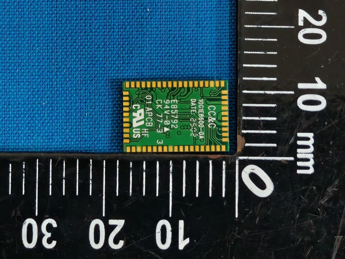
PANBM3095
Jun 24, 2026Bluetooth v5.4 APTX LE Audio RX Module
Equipment Class
DSS - Part 15 Spread Spectrum Transmitter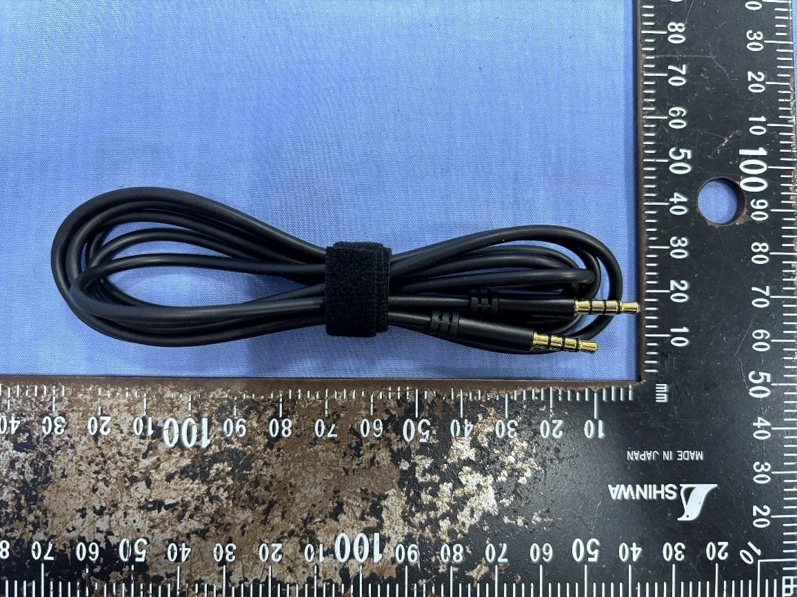
PANBA550T
Sep 26, 2024Triple source to BT5.3 LE Audio Transmitter
Equipment Class
DSS - Part 15 Spread Spectrum Transmitter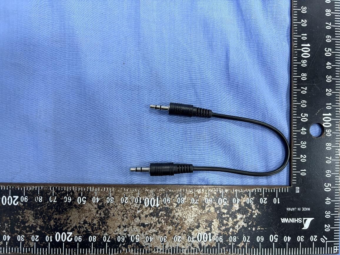
PANBA55T
Sep 26, 2024Dual source to BT5.3 LE Audio Transmitter
Equipment Class
DTS - Digital Transmission System
PANBA300M
Dec 08, 2022BT5 Aptx Audio Mixer
Equipment Class
DTS - Digital Transmission System
PANWA9563
Dec 17, 2020AC1200 FE Repeater
Equipment Class
NII - Unlicensed National Information Infrastructure TX