PATRX3UTEKOne Way Car Alarm System
U-TEK Engineering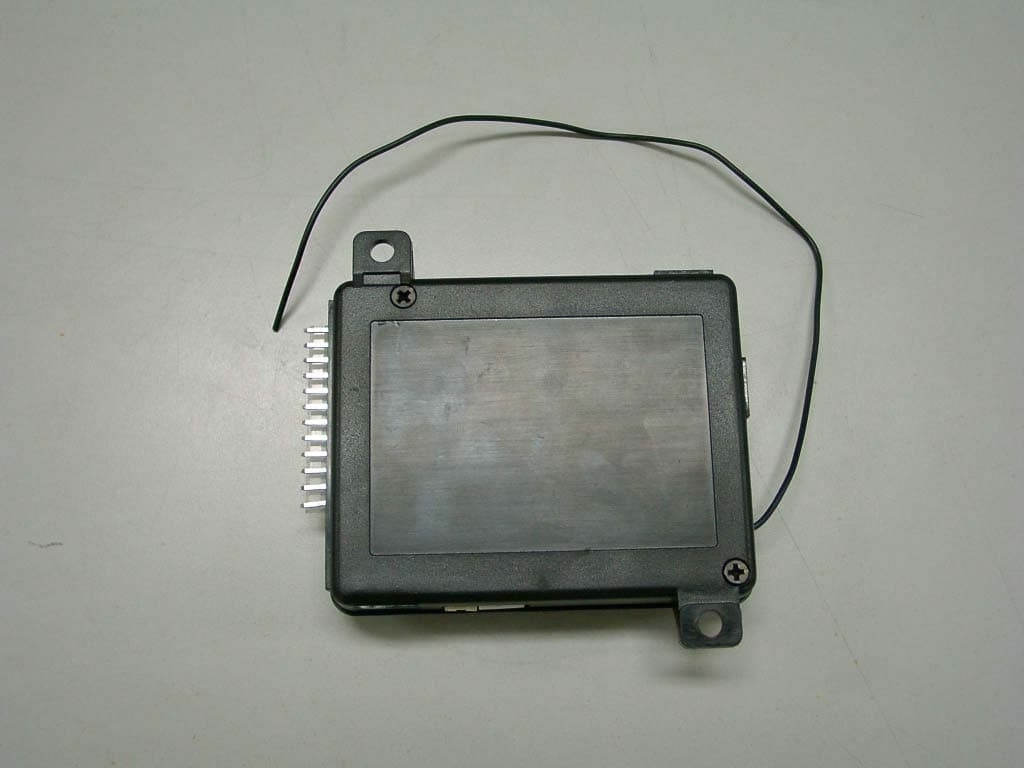
Click to zoom
Application Details
- Equipment Class
- CRR - Superregenerative Receiver
- Date of Grant
- Jun 03, 2003
- Application Purpose
- Original Equipment
- Date of Application
- Jun 03, 2003
- Equipment Note
- One Way Car Alarm System
- Frequency Range
- 311.00000000 - 311.00000000
- Company
- U-TEK Engineering
- Country
- South Korea
Documents & Files

Document Text
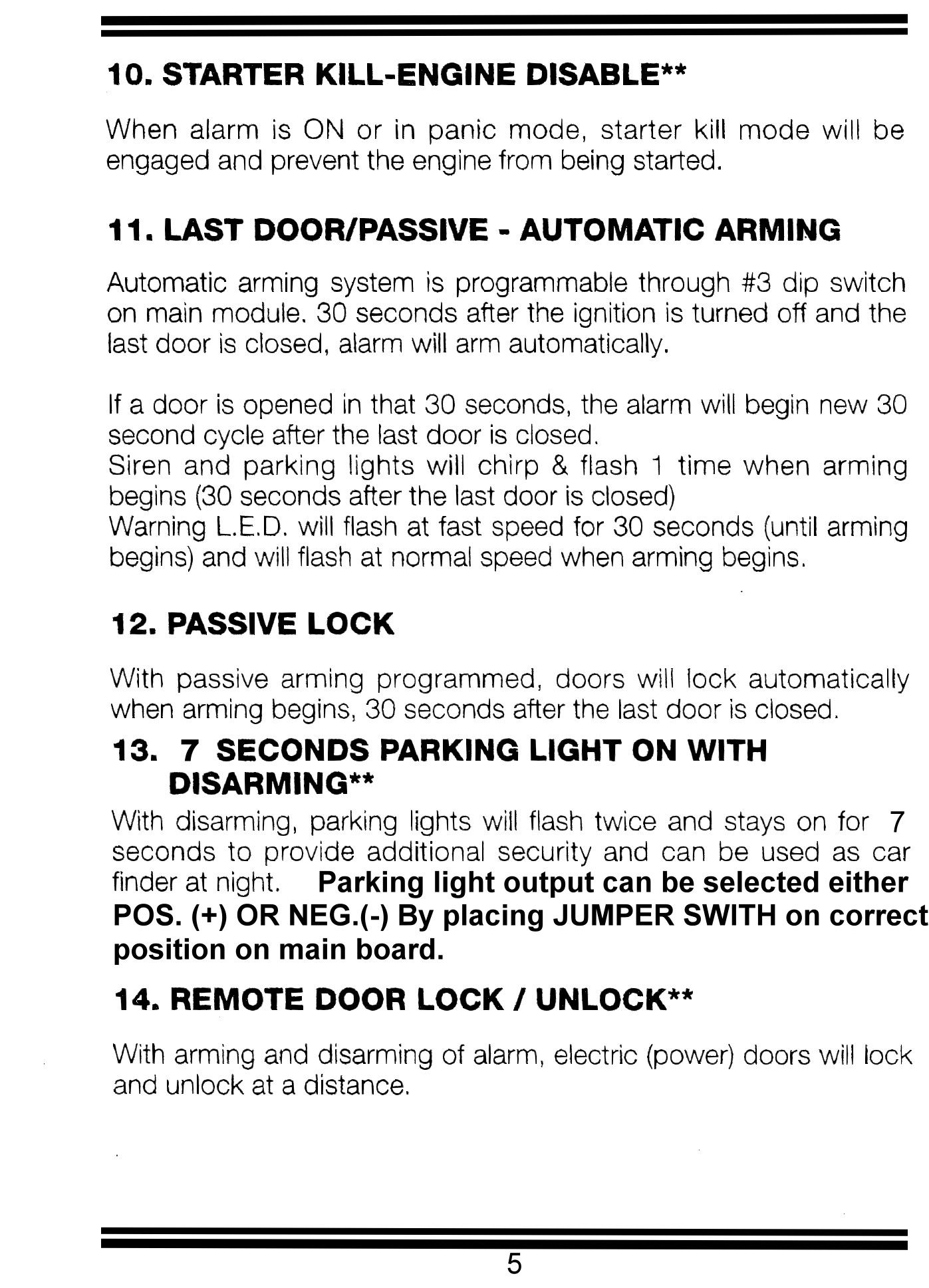
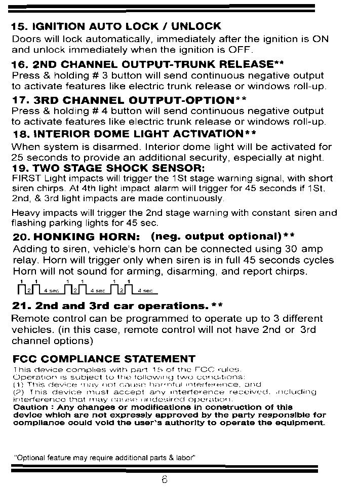
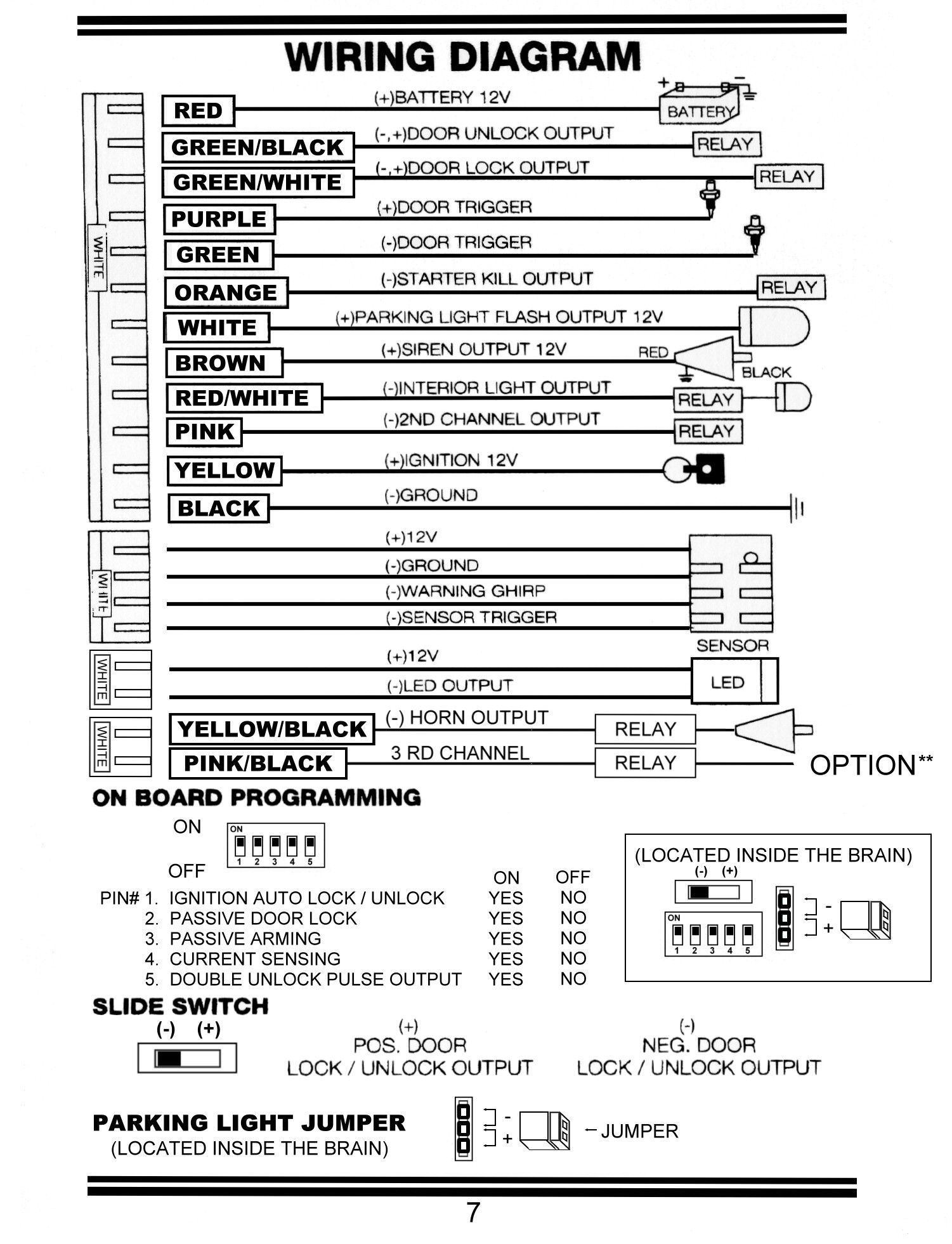
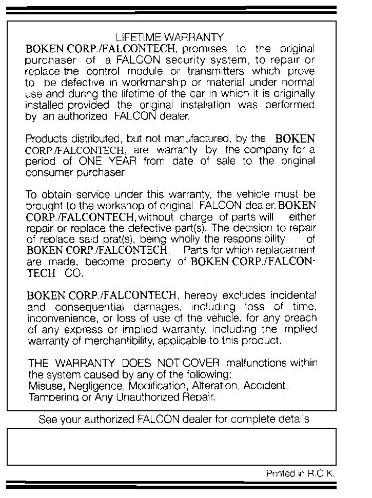
Text extracted from the exhibit documents filed with the FCC. Open a document above to read the original.
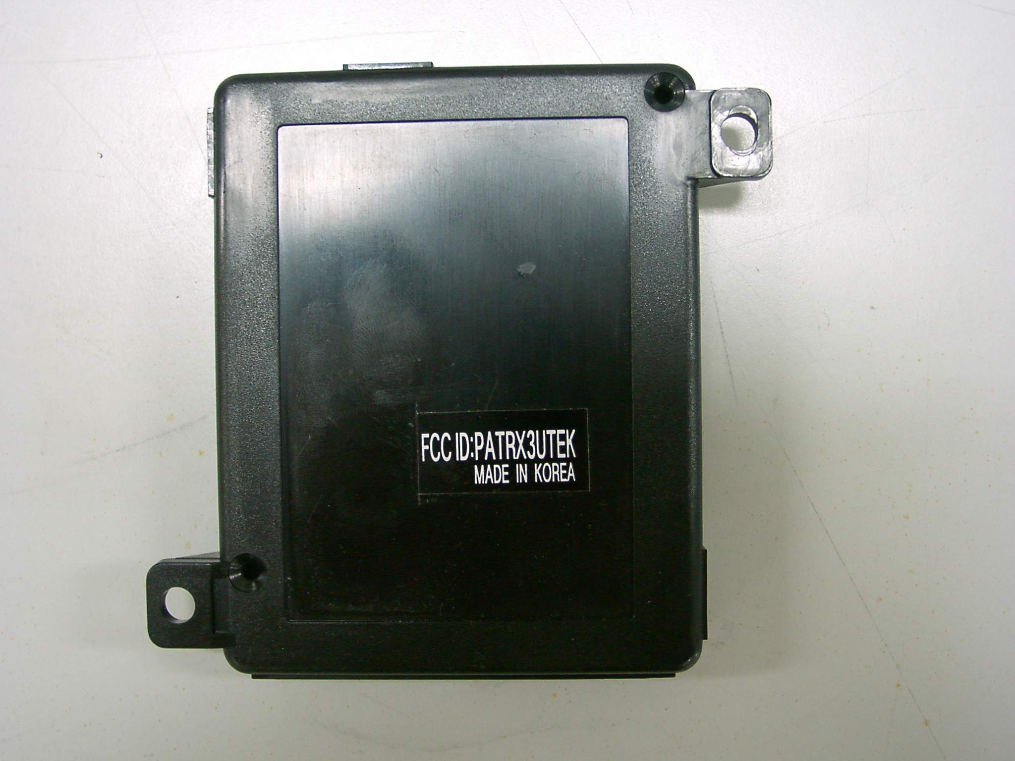
External Photos
External Photos
Internal Photos
Internal Photos
Operational Description
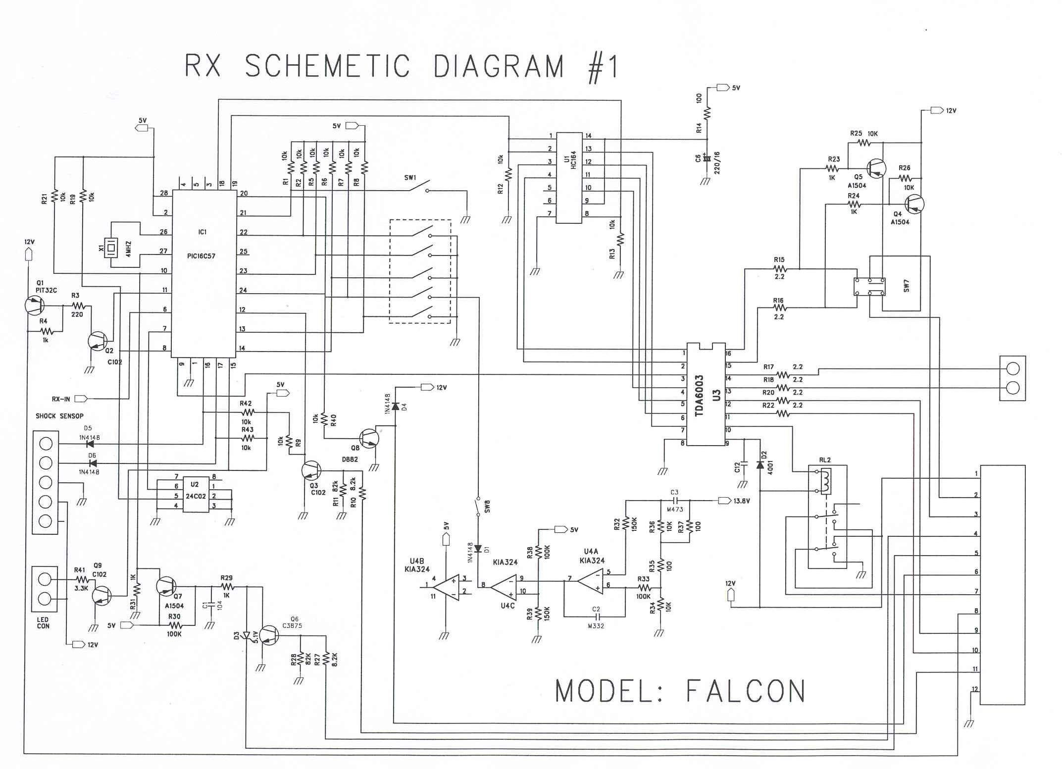
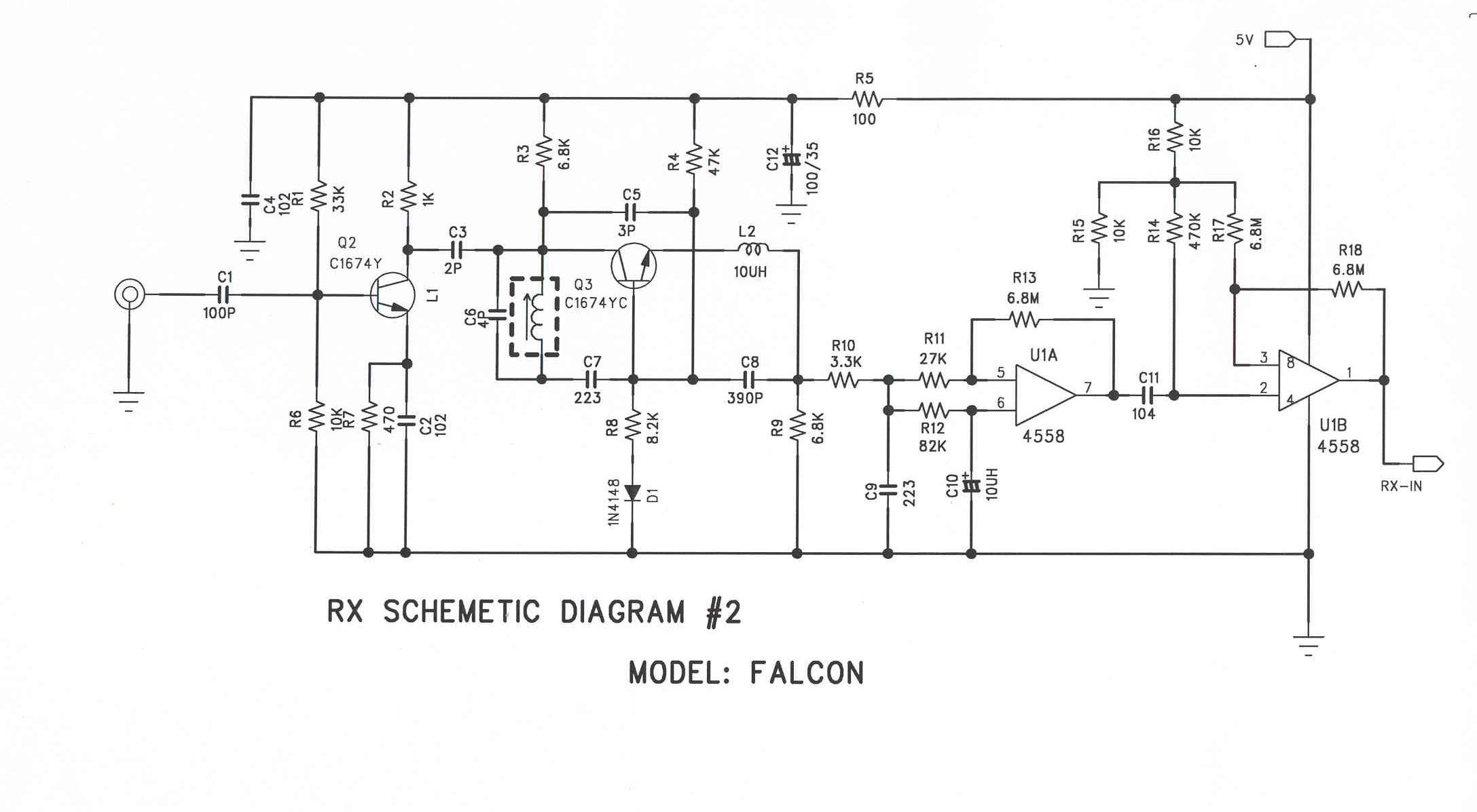
Operating Description of Receiver The received signal of 311MHZ from C1 is amplified by Q2 which is 1st. RF amplifier and C3 is output of this amplifier. This signal is supplied to Q3 circuits. The Q3 circuits is Local Oscillator, Mixer and Detector. The detected signal is come out from L2 and amplified 300 times by OP AMP U1A at first and amplified by U1B at pin No. 2. The final amplified detected signal is come out from pin No.1 of U1B.
Test Report
KTL Korea Testing Laboratory Page 1 of 8 TEST REPORT Ref. Report No. 03-341-015 This test report only responds to the tested sample and shall not be reproduced except in full without written approval of the Korea Testing Laboratory. Tested and reported by Reviewed by Name and address of the applicant U-Tek Engineering 1F, #256-1, Simgok-dong, Seo-gu, Inchon, 404-190 Korea Standard / Test regulation FCC Part 15, Subpart B Test result Pass Incoming date : April 16, 2003 Test item(s) ; Superregenerative Receiver (One Way Car Alarm System) Model/type ref. ; Falcon Manufacturer ; U-Tek Engineering Additional information ; -Required Authorization : Certification -FCC ID. : PATRX3UTEK Test date : May 20, 2003 Issue date : May 27, 2003 Jeong-Min Kim, Senior Engineer Hee-Soo Kim , Telecommunication Team Manager KOREA TESTING LABORATORY FG101-01-02-00 222-13, Guro-Dong Guro-Gu Seoul Korea 152-053 http://www.ktl.re.kr Ref. Report No. 03 - 341 – 015 Page 2 of 8 TABLE OF CONTENTS I. GENERAL INFORMATION 3 1. Grantee’s Name and Mailing Address 2. Manufacturer's Name and Mailing Address 3. Equipment Descriptions 4. Rules and Regulations 5. Measuring Procedure 6. Place of Measurement 7. Date of Measurement . GENERAL REQUIREMENTS OF THE EUT 4 1. Labeling Requirement (Section 15.19) 2. Information to User (Sections 15.21) 3. Special Accessories (Section 15.27) . RADIATED EMISSION MEASUREMENT (Section 15.109) 5 1. Test Procedure 2. Photograph for the test configuration 3. Sample Calculation 4. Measurement Data . TEST EQUIPMENTS USED FOR MEASUREMENT 8 Korea Testing Laboratory Telecommunication Team 222-13, Guro3-dong, Guro-gu, Seoul Korea 152-848 Ref. Report No. 03 - 341 – 015 Page 3 of 8 . GENERAL INFORMATION 1. Grantee’s Name and : U-Tek Engineering Mailing Address 1F, #256-1, Simgok-dong, Seo-gu, Inchon, 404-190, Korea 2. Manufacturer's Name and : U-Tek Engineering Mailing Address 1F, #256-1, Simgok-dong, Seo-gu, Inchon, 404-190, Korea 3. Equipment Descriptions 3.1 Tunning Frequency : 311.0 MHz 3.2 Detect Method : Superregenerative Detector 3.3 Power Supply : DC 12V(Car Battery) 4. Rules and Regulations : FCC Part 15, Subpart B 5. Measuring Procedure : ANSI C63.4 6. Place of Measurement : Absorber-lined Room (KTL) 7. Date of Measurement 7.1 Conducted Emission : Not Applicable 7.2 Radiated Emission : May 20, 2003 Korea Testing Laboratory Telecommunication Team 222-13, Guro3-dong, Guro-gu, Seoul Korea 152-848 Ref. Report No. 03 - 341 – 015 Page 4 of 8 . GENERAL REQUIREMENTS OF THE EUT 1. Labeling Requirement (Section 15.19) This device complies with Part 15 of the FCC Rules. Operation is subject to the following two conditions: (1) this device may not cause harmful interface, and (2) this device must accept any interference received, including interference that may cause undesired operation. 1.1 Location of Label : User’s Guide Manual 1.2 How Applied : Printed 2. Information to User (Section 15.21) The following or similar statements were provided in the manual for user instruction. Please refer page 6 of the attached manual for details. CAUTION : Any changes or modifications in construction of this device which are not expressly approved by the party responsible for compliance could void the user's authority to operate the equipment. 3. Special Accessories (Section 15.27) 3.1 Were the special Accessories provided? [ ] yes, [ x ] no 3.2 If yes, details for the special accessories are as follows : 3.3 If yes, were the appropriate instructions provided on the first page of the text concerned with the installation of the device? [ ] yes, [ ] no 3.4 Are these accessories provided of the type which can be readily obtained from multiple retail outlets ? [ ] yes, [ ] no And therefore does the manual specify what additional components or accessories are required to used in order to comply with the Rules? [ ] yes, [ ] no Korea Testing Laboratory Telecommunication Team 222-13, Guro3-dong, Guro-gu, Seoul Korea 152-848 Ref. Report No. 03 - 341 – 015 Page 5 of 8 . RADIATED EMISSION MEASUREMENT (Section 15.109) 1. Test Procedure 1.1 Preliminary Testing for Reference Preliminary testing was performed in a KTL absorber-lined room to determine the emission characteristics of the EUT. The EUT was placed on the wooden table which has dimensions of 0.8 meters in height, 1 meter in length and 1.5 meters in width. Receiving antenna (Biconical antenna : 30 to 300MHz, Log-periodic antenna : 200 to 1000MHz or Horn Antenna : 1 to 18GHz) was placed at the distance of 1 meter from the EUT. In order to cohere the individual components of the characteristic broadband emission from the receiver(EUT), a RF generator(CW signal) and a log-periodic antenna were used. The frequency and output level of the generator were adjusted for highest observed coherent receiver emissions on the spectrum analyzer with RF amplifier. An attempt was made to maximize the emission level with the various configurations of the EUT. The effect of changing the position of the cable was observed to find the worst case configuration while rotating the table and varying antenna height and it’s polarization. Radiated and spurious emissions were checked from 30 MHz to 3000 MHz according to section 15.33. 1.2 Final Radiated Emission Test at an Absorber-Lined Room The final measurement of radiated field strength was carried out in a KTL Absorber-Lined Room that was listed up at FCC according to the "Radiated Emissions Testing" procedure specified by ANSI C63.4. Based on the test results in preliminary test, measurement was made in same test set up and configuration which produced maximum emission level. Receiving antenna was installed at 3-meter distance from the EUT, and was connected to an EMI receiver or spectrum analyzer(for above 1GHz) with a RF amplifier. Turntable was rotated through 360 degrees and receiving antenna height was varied from 1 to 4 meters above the ground plane to read maximum emission level. The maximum emission level from the EUT occurred i…
Text truncated - open the document above for the full version.
Test Setup Photos
Ref. Report No. 03 - 341 – 015 Page 6 of 8 2. Photograph of the test configuration 3. Sample Calculation The emission level measured in decibels above one microvolt (dB ) was converted into microvolt per meter ( /m) as shown in following sample calculation. For example : Measured Value at 312.0 MHz 37.9 dB + Antenna Factor 14.0 dB/m + Cable Loss 3.3 dB - Preamplifier 30.0 dB - Distance Correction Factor * 0.0 dB ------------------------------------------------------------------------------------------- = Radiated Emission 25.2 dB /m ( = 18.2 /m ) * Extrapolated from the measured distance to the specified distance by an inverse linear distance extrapolation. Korea Testing Laboratory Telecommunication Team 222-13, Guro3-dong, Guro-gu, Seoul Korea 152-848
Contact Information
Applicant
You-Hyun Hwang(President)
Test Firm
Korea Testing LaboratoryJeong-Min Kim
Technical Specifications
| # | Rule Parts | Frequency Range | Power Output |
|---|---|---|---|
| 1 | 15B | 311 MHz - 311 MHz | - |
Other Applications from U-TEK Engineering
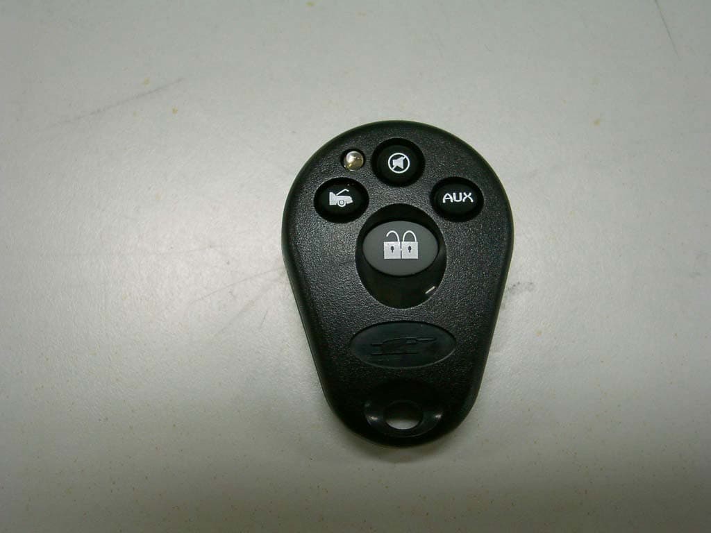
PATTX3UTEK
Jun 03, 2003One way car alarm system
Equipment Class
DSC - Part 15 Security/Remote Control Transmitter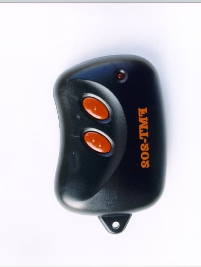
PATTX1UTEK
Nov 12, 2000DSC - Part 15 Security/Remote Control Transmitter
Equipment Class
DSC - Part 15 Security/Remote Control Transmitter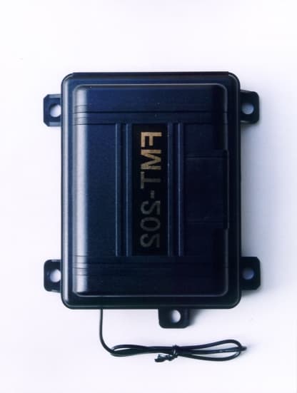
PATRX1UTEK
Nov 01, 2000RF Remote Switch
Equipment Class
CRR - Superregenerative Receiver