PB24220CF10Bar Code Scanner and WiFi Interface
Wav Inc.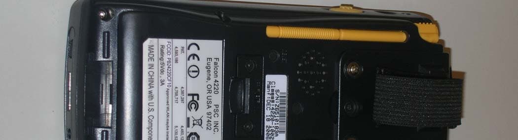
Click to zoom
Application Details
- Equipment Class
- DTS - Digital Transmission System
- Date of Grant
- Nov 07, 2007
- Application Purpose
- Original Equipment
- Date of Application
- Nov 07, 2007
- Equipment Note
- Bar Code Scanner and WiFi Interface
- Frequency Range
- 2412.00000000 - 2462.00000000
- Company
- Wav Inc.
- Country
- United States
Documents & Files
Document Text
Text extracted from the exhibit documents filed with the FCC. Open a document above to read the original.
Users Manual
Quick Reference Guide Falcon ® 4220 Windows CE ® .NET Ruggedized PDA 2432.book Page 1 Thursday, May 13, 2004 12:07 PM PSC Inc 959 Terry Street Eugene, Oregon 97402 Telephone: (541) 683-5700 Fax: (541) 345-7140 An Unpublished Work - All rights reserved. No part of the contents of this documentation or the procedures described therein may be reproduced or transmitted in any form or by any means without prior written permission of PSC Inc. or its wholly owned subsidiaries ("PSC"). Owners of PSC products are hereby granted a non-exclusive, revocable license to reproduce and transmit this documentation for the purchaser's own internal business purposes. Purchaser shall not remove or alter any proprietary notices, including copyright notices, contained in this documentation and shall ensure that all notices appear on any reproductions of the documentation. Should future revisions of this manual be published, you can acquire printed versions by contacting PSC Customer Administration. Electronic versions may either be downloadable from the PSC web site (www.pscnet.com) or provided on appropriate media. If you visit our web site and would like to make comments or suggestions about this or other PSC publications, please let us know via the “Contact PSC” page. Disclaimer Reasonable measures have been taken to ensure that the information included in this manual is complete and accurate. However, PSC reserves the right to change any specification at any time without prior notice. PSC is a registered trademark of PSC Inc. The PSC logo is a trademark of PSC. All other trademarks and trade names referred to herein are property of their respective owners. Falcon is a registered trademark of PSC Inc. and of its wholly owned subsidiaries. Microsoft Windows ® , Windows ® 2000, Windows® CE .NET, Windows ® NT, and Windows ® XP are registered trade- marks of Microsoft Corporation. Patents This product may be covered by one or more of the following patents: 4593186 • 4758717 • 5130520 • 4460120. 2432.book Page 2 Thursday, May 13, 2004 12:07 PM Quick Reference Guide 1 Table of Contents Introduction . . . . . . . . . . . . . . . . . . . . . . . . . . . . . . . . . . . . . . . . . . . . . . . . . . . . . 3 Before Getting Started . . . . . . . . . . . . . . . . . . . . . . . . . . . . . . . . . . . . . . . . . . 3 Features of the PDA . . . . . . . . . . . . . . . . . . . . . . . . . . . . . . . . . . . . . . . . . . . . . . . . 5 Batteries . . . . . . . . . . . . . . . . . . . . . . . . . . . . . . . . . . . . . . . . . . . . . . . . . . . . . . . 9 Charging the Battery . . . . . . . . . . . . . . . . . . . . . . . . . . . . . . . . . . . . . . . . . . . . 9 Charging the Battery Pack . . . . . . . . . . . . . . . . . . . . . . . . . . . . . . . . . . . . . . . 10 Setting Up the PDA . . . . . . . . . . . . . . . . . . . . . . . . . . . . . . . . . . . . . . . . . . . . . . . 13 Starting the Device . . . . . . . . . . . . . . . . . . . . . . . . . . . . . . . . . . . . . . . . . . . 13 Adjusting the Brightness . . . . . . . . . . . . . . . . . . . . . . . . . . . . . . . . . . . . . . . . 13 Calibrating the Touch Screen . . . . . . . . . . . . . . . . . . . . . . . . . . . . . . . . . . . . . 14 Setting up the RF Card . . . . . . . . . . . . . . . . . . . . . . . . . . . . . . . . . . . . . . . . . 14 Adjusting the Volume . . . . . . . . . . . . . . . . . . . . . . . . . . . . . . . . . . . . . . . . . . 14 Setting the Date and Time . . . . . . . . . . . . . . . . . . . . . . . . . . . . . . . . . . . . . . . 15 Entering Data . . . . . . . . . . . . . . . . . . . . . . . . . . . . . . . . . . . . . . . . . . . . . . . . . . . 15 Using the Stylus . . . . . . . . . . . . . . . . . . . . . . . . . . . . . . . . . . . . . . . . . . . . . . 16 Using the Keypad . . . . . . . . . . . . . . . . . . . . . . . . . . . . . . . . . . . . . . . . . . . . 16 Input States (Modes) . . . . . . . . . . . . . . . . . . . . . . . . . . . . . . . . . . . . . . . . . . 18 Navigating the Display . . . . . . . . . . . . . . . . . . . . . . . . . . . . . . . . . . . . . . . . . . . . . 20 The Command Bar . . . . . . . . . . . . . . . . . . . . . . . . . . . . . . . . . . . . . . . . . . . . 20 The Task Bar . . . . . . . . . . . . . . . . . . . . . . . . . . . . . . . . . . . . . . . . . . . . . . . . 21 Soft Keypad/Input Panel . . . . . . . . . . . . . . . . . . . . . . . . . . . . . . . . . . . . . . . . 21 Scanning Bar Codes . . . . . . . . . . . . . . . . . . . . . . . . . . . . . . . . . . . . . . . . . . . 22 Context Sensitive Help . . . . . . . . . . . . . . . . . . . . . . . . . . . . . . . . . . . . . . . . . . . . . 23 Resetting the PDA . . . . . . . . . . . . . . . . . . . . . . . . . . . . . . . . . . . . . . . . . . . . . . . . 24 Warm Reset . . . . . . . . . . . . . . . . . . . . . . . . . . . . . . . . . . . . . . . . . . . . . . . . . 24 Cold Reset . . . . . . . . . . . . . . . . . . . . . . . . . . . . . . . . . . . . . . . . . . . . . . . . . . 24 Technical Support . . . . . . . . . . . . . . . . . . . . . . . . . . . . . . . . . . . . . . . . . . . . . . . . 25 2432.book Page 1 Thursday, May 13, 2004 12:07 PM 2Falcon ® 4220 Windows ® CE PDA Appendix A: PSC Falcon ® WinCE End User License Agreement . . . . . . . . . 27 Appendix B: Microsoft ® Windows ® CE .NET End User License Agreement 30 Appendix C: PSC Falcon ® Warranty . . . . . . . . . . . . . . . . . . . . . . . . . . . . . . 31 Appendix D: Safety Information . . . . . . . . . . . . . . . . . . . . . . . . . . . . . . . . 32 Safety Labels . . . . . . . . . . . . . . . . . . . . . . . . . . . . . . . . . . . . . . . . . . . . . . . . . . . 32 Advisory Statements . . . . . . . . . . . . . . . . . . . . . . . . . . . . . . . . . . . . . . . . . . 34 Regulatory Statements . . . . . . . . . . . . . . . . . . . . . . . . . . . . . . . . . . . . . . . . . . . . 34 Radio Frequency Interference . . . . . . . . . . . . . . . . . . . . . . . . . . . . . . . . . . . . 34 Canadian …
Text truncated - open the document above for the full version.
Users Manual
Summit Quick Start Guide 09/24/07 Summit Data Communications, Inc. i Summit Data Communications, Inc. Quick Start Guide for a Summit radio card or module with software version 1.03 21 September 2007 Summit Quick Start Guide 09/24/07 Summit Data Communications, Inc. 1 Overview SDC-CF10G SDC-CF20G Thank you for choosing one of the following products from Summit Data Communications, Inc.: • SDC-CF10G compact flash radio module with antenna connectors • SDC-CF20G compact flash radio card with integrated antennas • SDC-PC10G PCMCIA radio module with antenna connectors • SDC-PC20G PCMCIA radio card with integrated antennas (If you are using the SDC-MCF10G miniature compact flash radio module with antenna connectors, contact Summit for hardware installation information and assistance. The software is the same as for other Summit products.) When you install and use your Summit radio module or card in a computing device, that device can communicate to a computing network using the IEEE 802.11g and IEEE 802.11b protocols. For details on the capabilities of Summit products, go to: http://www.summitdatacom.com/products.htm. The software that Summit provides for its radio modules runs on the computing device that houses a radio module. SDC-PC10G SDC-PC20G That software includes: • A device driver • An integrated IEEE 802.1X supplicant, which supports the highest level of standards-based WLAN security with a broad range of options • The Summit Client Utility (SCU), a configuration, monitoring, and management application designed for Summit radio modules • On Windows CE/Mobile, a service that displays a Windows System Tray icon that provides a visual status for the Summit radio and enables the user to launch SCU by tapping the icon This software runs on the following operating systems: • Windows CE .NET 4.2 and Windows Mobile (or Pocket PC) 2003 • Windows CE .NET 5.0 and Windows Mobile 5.0 and 6.0 • Windows XP and Windows XP Embedded (XPe) Your Summit radio module is Wi-Fi CERTIFIED ® and certified for Cisco Compatible Extensions (CCX): • Wi-Fi: The Wi-Fi Alliance certifies that Summit radio modules support 802.11b and 802.11g with WPA and WPA2, both Personal and Enterprise. The tested EAP type was PEAP-MSCHAPv2. For details, visit the Wi-Fi Alliance Web site at http://www.wi-fi.com, click on the “Wi-Fi CERTIFIED ® Products” link, and search for Summit Data Communications. • CCX: Summit radio modules are certified to Version 3 of the CCX specification for application- specific devices (ASDs). For an overview of CCX, go to http://www.cisco.com/web/partners/pr46/pr147/partners_pgm_concept_home.html. For details on Summit Quick Start Guide 09/24/07 Summit Data Communications, Inc. 2 the features in CCX V3 for ASDs, go to http://www.cisco.com/warp/public/765/ccx/versions_and_features.shtml. Getting Started Before you can use a Summit radio, you or your device manufacturer must install Summit software and the radio in your computing device. If you are doing the software and hardware installation, then you will need the following: • A mobile computing device: - With a compact flash (CF) Type I or Type II slot or a PCMCIA (PC Card) Type II slot - That runs one of the operating systems listed on page 1 • Summit software, which is available from the organization from which you purchased your Summit radio • A Summit radio module or radio card • For a 10G Series radio module, one or two antennas, each with a cable that is fitted with a Hirose U.FL connector that can be attached to an antenna connector on the radio module You will perform the following four steps: 1. Install the Summit software on your mobile computing device 2. Install the radio module in your device 3. Configure the manner of obtaining an IP address 4. Configure the radio to connect to your wireless network It is recommended that you install the software before you install the hardware. If you insert the card in your device before you install the software, then the "Found New Hardware Wizard" screen will appear, and you must select "Cancel" to cancel the Hardware Wizard. Step 1: Install the Summit Software Windows CE or Mobile Summit software is in a .cab file, which is the software equivalent of a “file cabinet”. A Summit .cab file contains all software components, including the device driver and the Summit Client Utility (SCU). To install the Summit software, perform these tasks: • Download the appropriate .cab file for the operating system and processor of your device. You can obtain your device’s operating system and processor from the system information under Windows Control Panel (Tap Start, then Settings, and then System or Control Panel) - Pocket PC or Mobile: Select a .cab file with a name that begins with “mobile”. - CE .NET: Do a search on your device’s processor to determine if it is an ARM v4i processor or an ARM v4 processor. If it is an ARM v4i processor, select a .cab file with a name that begins with “sdc_armv4i”. If it is an ARM v4 processor, select a .cab file with a name that begins with “sdc_armv4”. • Copy the file to your device using a supported file transfer mechanism. Common methods of moving the file include: - Place the file on a supported Compact Flash or SD memory card and use that card for copying the file to the device. - Use a program such as FTP or Microsoft ActiveSync. • On the device, use the resident File Explorer program to locate the .cab file. • Run the .cab file by single-clicking the file or by right-clicking and selecting “run”. • If asked to replace any existing files on the device, answer “Yes to all”. Summit Quick Start Guide 09/24/07 Summit Data Communications, Inc. 3 Windows XP On Windows XP, the process for installing Summit software is managed by a setup wizard named SummitInstall.msi. When you run this program, a sequence of screens guides you through the installation process. After you click the Next button on the initial welcome screen, you advance to a screen, shown at the right, on which you …
Text truncated - open the document above for the full version.
Cover Letter(s)
November 6, 2007 Equipment Autorization Division Federal Communications Commission 7435 Oakland Mills Road Columbia, MD 21046 FCC ID: TWG-SDCCF10G Product Name: SDC-CF10G 802.11g Compact Flash WLAN Radio Module Request for Confidentiality Pursuant to Sections 0.457 and 0.459 of the commissions rules, we hereby request that the following documents be held confidential: • Schematics • Block diagram These materials contain trade secrets and proprietary information and are not customarily released to the public. The public disclosure of this information might be harmful to the company and provide unjustified benefits to our competitors. Dated this 6 th Day of November 20 07 By: Ronald Seide Signature Printed Title: President On behalf of : Summit Data Communications, Inc. Telephone: 330.434.7929
External Photos
Page 1 CONSTRUCTION PHOTOS OF EUT Page 2
Internal Photos
Page 3 Page 4 Page 5 Page 6 Antenna 1 Page 7 Antenna 2 Page 8 Page 9 Antenna 3 Page 10
Operational Description
qÜÉçêó=çÑ=léÉê~íáçå= = ========kçîÉãÄÉê=TI=OMMT= = = cÉÇÉê~ä=`çããìåáÅ~íáçåë=`çããáëëáçå= = obW=`ÉêíáÑáÅ~íáçå=^ééäáÅ~íáçå= c``=faW=m_OQOOM`cNM= = = qç=tÜçã=fí=j~ó=`çåÅÉêåW= = qÜÉ=Ü~åÇÜÉäÇ=ÇÉîáÅÉ=Emp`La~í~äçÖáÅ=c~äÅçå=QOOMF=áë=~=ma^=Ñçêã=Ñ~ÅíçêI=Ä~ííÉêó= çéÉê~íÉÇ=Ü~åÇÜÉäÇ=ÅçãéìíÉê=ìëÉÇ=Ñçê=Ä~êÅçÇÉ=ëÅ~ååáåÖ=~åÇ=Ç~í~=ÅçääÉÅíáçå= ~ééäáÅ~íáçåëK=qÜÉ=pìããáí=`cNM=ti^k=ê~Çáç=ïÜáÅÜ=áë=Åçåí~áåÉÇ=áå=íÜÉ=QOOMÛë= áåíÉêå~ä=`çãé~Åí=cä~ëÜ=ëäçí=éêçîáÇÉë=ÅçååÉÅíáîáíó=íç=~=ã~áåÑê~ãÉ=Üçëí=Ñçê= íê~åëÑÉê=çÑ=Ç~í~=ÉåíÉêÉÇ=îá~=íÜÉ=QOOMÛë=âÉóÄç~êÇI=ëÅ~ååÉê=~åÇ=íçìÅÜ=ëÅêÉÉåK= = páåÅÉêÉäóI= = `Ü~êäÉë=aK=_çäîáå= sm=qÉÅÜåçäçÖó= t^s=fåÅK=
Operational Description
SPECIFICATION FOR APPROVAL CUSTOMER DATE DESCRIPTION CUSTOMER P/N WANSHIH ELECTRONIC CO., LTD. 723 3F 72 WU KONG 6TH RD., WU KU INDUSTRIAL DISTRICT TAIPEI HSIEN, TAIWAN, R.O.C. TEL(02) 22988066 (5 LINE) FAX(02)22981102 92 7 4 3907-001100 1 Table of Contents Table of Contents ......... 1 Specification ......... 2 Antenna Drawing ......... 3 Electrical Properties Return Loss ......... 4 V. S . W. R ......... 5 Radiation Pattern ......... 6-11 Material Data Sheet Coaxial Cable ......... 12-14 SPTE ......... 15 I-PEX MHF connector 16-18 2 SPECIFICATION 1. Description WPF001 2400MHz PIFA with MHF 2. Customer 3. Model No. WPF001 4. Part No. SIW0098A 5. Product Merits IEEE 802.11b 11Mbps Wireless LAN 6. Antenna Profile 34.5*32.2*0.3 mm (see Drawing) 7. Color N/A 8. Electrical Characteristics Operating Frequency 2.4~2.5Ghz Antenna Type PIFA Polarization Type Linear Type of Radiation Toroidal Peak Gain 0 dBi Typical Impedance 50 Ohm nominal V.S.W.R. 2.0:1 Max. 9. Mechanical Characteristics Lead Length 120 mm (see Drawing) Connector IPEX MHF Core N/A Polyethylene Foam N/A Acrylic Foam Tape N/A 10. Raw Material Coaxial Cable 3.2AWG*1C SP7/0.080 1.13MM Antenna Body SPTE Per JIS G3303 SPTE MR T-38A 3 3907-001100 4 Electrical Properties Return Loss 5 Electrical Properties V. S . W. R 6 Electrical Properties Radiation Pattern – YZ Plane(Horizontal) 7 Electrical Properties Radiation Pattern – YZ Plane (Vertical) 8 Electrical Properties Radiation Pattern – XY Plane (Horizontal) 9 Electrical Properties Radiation Pattern – XY Plane (Vertical) 10 Electrical Properties Radiation Pattern – XZ Plane (Horizontal) 11 Electrical Properties Radiation Pattern – XZ Plane (Vertical) 12 Material Data Sheet Mini-1.13 Coaxial Cable 13 14 15 Material Data Sheet SPTE 16 Material Data Sheet MHF Connector 17 Material Data Sheet MHF Connector 18 Material Data Sheet MHF Connector
Test Report
Report No.: RF941208L111Report Format Version 2.0.4 FCC TEST REPORT REPORT NO.: RF941208L11 MODEL NO.: SDC-CF10G RECEIVED: Dec. 05, 2005 TESTED: Dec. 05, 2005 ~ Mar. 31, 2006 ISSUED: Apr. 06, 2006 APPLICANT:Summit Data Communications, Inc. ADDRESS:526 South Main Street Suite 411, Akron, Ohio, 44311 United States ISSUED BY: Advance Data Technology Corporation LAB ADDRESS: 47 14 th Lin, Chiapau Tsun, Linko, Taipei, Taiwan, R.O.C. TEST LOCATION: No. 19, Hwa Ya 2 nd Rd., Kueishan, Taoyuan, Taiwan, R.O.C. This test report consists of 76 pages in total. It may be duplicated completely for legal use with the approval of the applicant. It should not be reproduced except in full, without the written approval of our laboratory. The client should not use it to claim product endorsement by CNLA, A2LA or any government agencies. The test results in the report only apply to the tested sample. No. 2177-01 Report No.: RF941208L112Report Format Version 2.0.4 Table of Contents 1CERTIFICATION..............................................................................................................4 2SUMMARY OF TEST RESULTS......................................................................................5 2.1MEASUREMENT UNCERTAINTY..............................................................................5 3GENERAL INFORMATION..............................................................................................6 3.1GENERAL DESCRIPTION OF EUT...........................................................................6 3.2DESCRIPTION OF TEST MODES.............................................................................7 3.2.1CONFIGURATION OF SYSTEM UNDER TEST.........................................................7 3.2.2TEST MODE APPLICABILITY AND TESTED CHANNEL DETAIL..............................8 3.3GENERAL DESCRIPTION OF APPLIED STANDARDS...........................................10 3.4DESCRIPTION OF SUPPORT UNITS.....................................................................10 4TEST TYPES AND RESULTS........................................................................................11 4.1CONDUCTED EMISSION MEASUREMENT............................................................11 4.1.1LIMITS OF CONDUCTED EMISSION MEASUREMENT..........................................11 4.1.2TEST INSTRUMENTS..............................................................................................11 4.1.3TEST PROCEDURES..............................................................................................12 4.1.4DEVIATION FROM TEST STANDARD.....................................................................12 4.1.5TEST SETUP...........................................................................................................13 4.1.6EUT OPERATING CONDITIONS.............................................................................13 4.1.7TEST RESULTS.......................................................................................................14 4.2RADIATED EMISSION MEASUREMENT.................................................................20 4.2.1LIMITS OF RADIATED EMISSION MEASUREMENT...............................................20 4.2.2TEST INSTRUMENTS..............................................................................................21 4.2.3TEST PROCEDURES..............................................................................................22 4.2.4DEVIATION FROM TEST STANDARD.....................................................................22 4.2.5TEST SETUP...........................................................................................................23 4.2.6EUT OPERATING CONDITIONS.............................................................................23 4.2.7TEST RESULTS.......................................................................................................24 4.36dB BANDWIDTH MEASUREMENT........................................................................38 4.3.1LIMITS OF 6dB BANDWIDTH MEASUREMENT......................................................38 4.3.2TEST INSTRUMENTS..............................................................................................38 4.3.3TEST PROCEDURE.................................................................................................39 4.3.4DEVIATION FROM TEST STANDARD.....................................................................39 4.3.5TEST SETUP...........................................................................................................39 4.3.6EUT OPERATING CONDITIONS.............................................................................39 4.3.7TEST RESULTS.......................................................................................................40 4.4MAXIMUM PEAK OUTPUT POWER........................................................................46 4.4.1LIMITS OF MAXIMUM PEAK OUTPUT POWER MEASUREMENT.........................46 4.4.2TEST INSTRUMENTS..............................................................................................46 4.4.3TEST PROCEDURES..............................................................................................47 4.4.4DEVIATION FROM TEST STANDARD.....................................................................47 4.4.5TEST SETUP...........................................................................................................47 4.4.6EUT OPERATING CONDITIONS.............................................................................47 4.4.7TEST RESULTS.......................................................................................................48 4.5POWER SPECTRAL DENSITY MEASUREMENT....................................................49 4.5.1LIMITS OF POWER SPECTRAL DENSITY MEASUREMENT..................................49 4.5.2TEST INSTRUMENTS..............................................................................................49 4.5.3TEST PROC…
Text truncated - open the document above for the full version.
Test Report
Underwriters Laboratories Inc. 333 Pfingsten Rd. Northbrook, IL 60062 www.ul.com/emc (847) 272-8800 Job Number: 757056 Project Number: 07NK23934 File Number: MC1343 FCC ID: PB24220CF10 Date: October 30, 2007 Model: Falcon 4220 Electromagnetic Compatibility Test Report For Wav Inc. Copyright © 2007 Underwriters Laboratories Inc. Underwriters Laboratories Inc. authorizes the above-named company to reproduce this Report provided it is reproduced in its entirety. Underwriters Laboratories Inc. A not-for-profit organization dedicated 333 Pfingsten Rd. Northbrook, IL 60062 Tel: (847) 272-8800 to public safety and committed to quality service for over 100 years Job Number: 757056 File Number: MC1343 Project Number: 07NK23934 Page2 of 67 Model Number: Falcon 4220 Client Name: Wav Inc. FCC ID: PB24220CF10 Test Report Details Tests Performed By: Underwriters Laboratories Inc. 333 Pfingsten Rd. Northbrook, IL 60062 Tests Performed For: Wav Inc. 245 West Roosevelt Road Building 7, Suite 48 West Chicago, IL 60185 Applicant Contact: Chuck Bolvin Title: Phone: (630) 818-1006 Fax: E-mail: [email protected] Test Report Date: October 30, 2007 Product Type: PDA with Bar Code Scanner and WiFi Interface Product standards 47 CFR Part 15.247 (d) – Radiated Emissions Only Model Number: Falcon 4220 EUT Category: Wireless Device Testing Start Date: October 22, 2007 Date Testing Complete: October 30, 2007 Overall Results: Compliant Underwriters Laboratories Inc. reports apply only to the specific samples tested under stated test conditions. All samples tested were in good operating condition throughout the entire test program. It is the manufacturer's responsibility to assure that additional production units of this model are manufactured with identical electrical and mechanical components. Underwriters Laboratories Inc. shall have no liability for any deductions, inferences or generalizations drawn by the client or others from Underwriters Laboratories Inc. issued reports. This report shall not be used to claim, constitute or imply product certification, approval, or endorsement by NVLAP, A2LA, or any agency of the US government. This report may contain test results that are not covered by the NVLAP or A2LA accreditation. The scope of accreditation is limited to the specific tests that are listed on the NVLAP and/or A2LA websites referenced at the end of this report. Underwriters Laboratories Inc. 333 Pfingsten Rd. Northbrook, IL 60062 USA Tel.: 847 272-8800 Rev. No 1.0 EMC Report 2007 Job Number: 757056 File Number: MC1343 Project Number: 07NK23934 Page3 of 67 Model Number: Falcon 4220 Client Name: Wav Inc. FCC ID: PB24220CF10 Report Directory 1.0 G E N E R A L - Product Description..................................................................................................................4 1.1 Equipment Description...................................................................................................................................4 1.2 Device Configuration During Test..................................................................................................................4 1.2.1 Equipment Used During Test:....................................................................................................................4 1.2.2 Input/Output Ports:.....................................................................................................................................4 1.2.3 EUT Internal Operating Frequencies:........................................................................................................4 1.2.4 Power Interface:.........................................................................................................................................5 1.3 EUT Configurations........................................................................................................................................5 1.4 EUT Operation Modes....................................................................................................................................5 2.0 Summary............................................................................................................................................................5 2.1 Deviations from standard test methods..........................................................................................................5 2.2 Device Modifications Necessary for Compliance...........................................................................................5 2.3 Reference Standards.....................................................................................................................................6 2.4 Results Summary...........................................................................................................................................6 3.0 Calibration of Equipment Used for Measurement..............................................................................................7 4.0 EMISSIONS TEST RESULTS............................................................................................................................7 4.1 Test Conditions and Results – MAINS TERMINAL – CONDUCTED EMISSIONS.......................................8 4.2 Test Conditions and Results – RADIATED EMISSIONS 30MHz – 25GHz................................................17 4.3 Test Conditions and Results – SPURIOUS RADIATED EMISSIONS 1GHz – 25GHz..............................25 4.4 Test Conditions and Results – SPURIOUS BANDEDGE RADIATED EMISSIONS...................................41 Appendix A...............................................................................................................................................................66 Accreditations and Authorizations............................................................................................................................66 Underwriters Laboratories Inc. 333 Pfingsten Rd. Northbrook, IL 60062 USA Tel.:…
Text truncated - open the document above for the full version.
Test Report
© 2007 RF Exposure Lab, LLC This report shall not be reproduced except in full without the written approval of RF Exposure Lab, LLC. 2867 Progress Place, Suite 4D • Escondido, CA 92029 • U.S.A. TEL (760) 737-3131 • FAX (760) 737-9131 http://www.rfexposurelab.com CERTIFICATE OF COMPLIANCE SAR EVALUATION WAV Wireless Outfitters Dates of Test: October 29, 2007 2380A Prospect Drive Test Report Number: SAR.20071005 Aurora, IL 60504 This wireless mobile and/or portable device has been shown to be compliant for localized specific absorption rate (SAR) for uncontrolled environment/general exposure limits specified in ANSI/IEEE Std. C95.1-1999 and had been tested in accordance with the measurement procedures specified in IEEE 1528-2003, OET Bulletin 65 Supp. C, RSS-102 and Safety Code 6 (See test report). I attest to the accuracy of the data. All measurements were performed by myself or were made under my supervision and are correct to the best of my knowledge and belief. I assume full responsibility for the completeness of these measurements and vouch for the qualifications of all persons taking them. RF Exposure Lab, LLC certifies that no party to this application has been denied FCC benefits pursuant to Section 5301 of the Anti-Drug Abuse Act of 1988, 21 U.S.C. 853(a). Jay M. Moulton Vice President Certificate # 2387.01 FCC ID: PB24220CF10 Model(s): PSC Falcon 4220 Summit WLAN: Model: SDG-CF10G FCC ID: TWG-SDCCF10G Test Sample: Production Serial No.: Z6510183A Equipment Type: Wireless Computer/Scanner Classification: Portable Transmitter Next to Body TX Frequency Range: 2412 – 2462 MHz Frequency Tolerance: ± 25 ppm Maximum RF Output: 2450 MHz (b) – 18.10 dBm, 2450 MHz (g) – 14.08 dBm Conducted Signal Modulation: DSSS, OFDM Antenna Type (Length): Wanshih Electronic Co., Ltd. Model WPF001 Battery: Model PC-320 Application Type: Certification FCC Rule Parts: Part 15C FCC ID: PB24220CF10 © 2007 RF Exposure Lab, LLC Page 2 of 70 This report shall not be reproduced except in full without the written approval of RF Exposure Lab, LLC. Table of Contents 1. Introduction ...........................................................................................................................3 SAR Definition [5]......................................................................................................................3 2. SAR Measurement Setup .....................................................................................................4 Robotic System ..........................................................................................…
Text truncated - open the document above for the full version.
Contact Information
Applicant
Charles D Bolvin(VP of Technology)
Technical Contact
Wav IncChuck Bolvin
630-818-1006
245 Roosevelt Rd. · West Chicago, Illinois · United States
Non-Technical Contact
Wav IncChuck Bolvin
630-818-1006
Test Firm
UL LLCRick Titus
Technical Specifications
| # | Rule Parts | Frequency Range | Power Output |
|---|---|---|---|
| 1 | 15C | 2.41 GHz - 2.46 GHz | 64.27 mW |
Other Applications from Wav Inc.
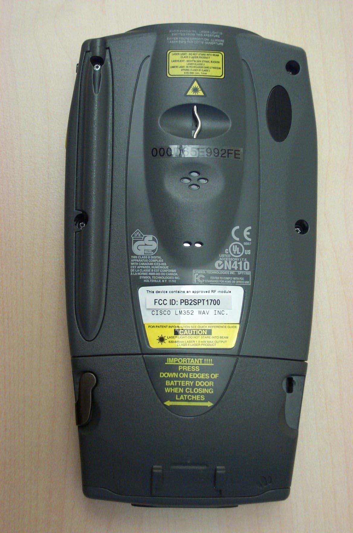
PB2SPT1700
Nov 17, 2003WAV ChameleonRF SPT1700
Equipment Class
DSS - Part 15 Spread Spectrum Transmitter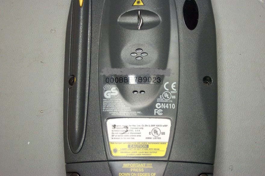
PB2SPT1800
Oct 08, 2003WAV ChameleonRF hand held terminal
Equipment Class
DSS - Part 15 Spread Spectrum Transmitter
PB2WT2270
Apr 24, 2003Wrist-worn scanner transmitter
Equipment Class
DSS - Part 15 Spread Spectrum Transmitter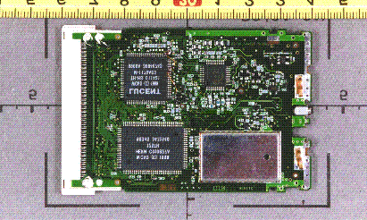
PB2WO80A
Mar 13, 2001Chameleon WLAN 80 Wireless LAN Adapter
Equipment Class
DSS - Part 15 Spread Spectrum Transmitter