PB2SPT1800WAV ChameleonRF hand held terminal
Wav Inc.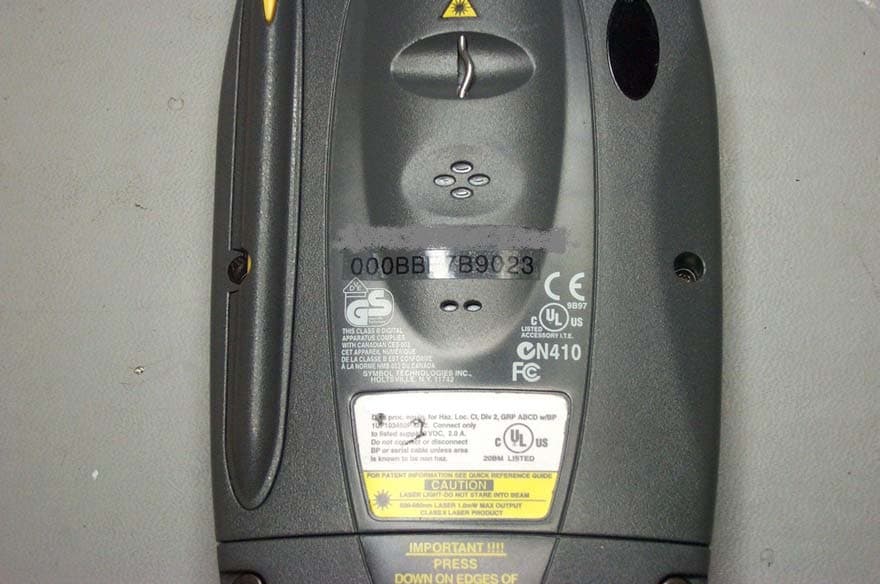
Click to zoom
Application Details
- Equipment Class
- DSS - Part 15 Spread Spectrum Transmitter
- Date of Grant
- Oct 08, 2003
- Application Purpose
- Original Equipment
- Date of Application
- Oct 08, 2003
- Equipment Note
- WAV ChameleonRF hand held terminal
- Frequency Range
- 2412.00000000 - 2462.00000000
- Company
- Wav Inc.
- Country
- United States
Documents & Files
Document Text
Text extracted from the exhibit documents filed with the FCC. Open a document above to read the original.
Users Manual
TAKE OUT WHAT YOU NEED INSTALL THE PC CARD CLIENT ADAPTER INSTALL THE APPROPRIATE DRIVER AND UTILITIES 1 2 3 Quick Start Guide CISCO AIRONET 350 SERIES PC CARD C LIENT ADAPTERS Laptops with PC card client adapters Access Point 1 Take Out What You Need If any item is missing or damaged, contact your Cisco representative or reseller for support. Note: The integrated antenna on PC models of the Aironet PC Client Card Adapter is permanently attached; LM models are shipped with no antenna. Additional Requirements •A computing device (desktop personal computer, notebook, laptop computer, portable or hand-held device) equipped with an internal or external PC Card Type II or Type III slot. All drivers and supporting software (card and socket services) for the PC card slot must be loaded and configured. •The following information from your system administrator: —your wireless client name —the (case-sensitive) wireless service set identification (SSID) for your radio network —for Microsoft Windows networking, your computer name and workgroup name —the username and password for your network account —if you are not connected to a DHCP server, the IP address, default gateway address, and subnet mask of your computer —for Windows NT systems, an available IRQ number (interrupt address) in your system Cisco Aironet 350 Series PC Card Client Adapter (labeled Wireless LAN Adapter) Cisco Aironet 350 Series PC Card Client Adapter CDs for Windows 95 and Windows NT or Windows 98 and Windows 2000 with software and product documentation CISCO AIRONET 340 SERIES 11 Mbps WIRELESS LAN ADAPTER 2 Install the PC Card Client Adapter CautionThe following procedures and physical connections apply generally to normal and conventional PC card slots. In cases of custom or non-conventional equipment, be alert to possible differences in PC card slot configurations. 1 Before you begin, examine the PC card client adapter. One end is a dual-row, 68-pin PC card connector. The card is keyed so that it can be inserted only one way into the PC card slot. The slot in your computing device must be a PC card Type II slot (this includes slots that support both the Type II and Type III cards). Note: The PC card slot will be on the left or right side of the computer, depending on the model. 2 For Windows 95 and Windows 98 systems, remove any other PC card from the card slot. 3 For Windows 95 or Windows 98 systems, turn the computer on before inserting the PC card client adapter. For Windows NT systems, turn the computer off before inserting the client adapter. CautionNever force the PC card client adapter into the PC card slot. Forcing it will damage both the PC card and the slot. If the PC card does not easily insert, remove the card and re-insert it. 4 Hold the PC card client adapter with the logo facing up and insert the card into the slot, applying just enough pressure to make sure it is fully seated. Proceed to the appropriate driver installation for your operating system. 3 Note: The following procedures assume you are installing the driver from the CD provided. If your PC does not have a CD-ROM drive, download the driver from Cisco’s web site. Install the Appropriate Driver and Utilities Windows 98 Systems Note: The Windows 98 driver also works with the Windows 2000 operating system. In Windows 98 systems, after you have installed the PC card client adapter, the system automatically detects it, opens a New Hardware Found window, and starts collecting information for a driver database. 1 When the Add New Hardware Wizard dialog box opens, it is searching for new drivers. Click Next. 2 From the next dialog box, select Search for the best driver for your device (Recommended) and click Next. 3 Select CD-ROM drive, deselect all other options, insert the Cisco Aironet 350 Series Client Adapter CD for Windows 98, and click Next. 4 The hardware wizard will find the installation files on the CD and display the search results. When the PCMCIA adapter driver is displayed, click Next to copy the required files. 5 During driver installation, you may be prompted to enter a path to the required client adapter or Windows 98 files: (a) Windows 98 files installed on your PC are usually located in the folder C:\Windows\Options\Cabs. Click OK to install. (b) If the system prompts you for the Windows CD and the CD-ROM drive on your PC is drive D, the path should be D:\WIN98. Click OK to copy the required files. 6 The Add New Hardware Wizard window again opens indicating that the installation is complete. Click Finish. 7 Remove the CD and restart your laptop. 8 When the computer restarts, double-click My Computer, Control Panel, and Network. 9 Select the PCMCIA adapter and click Properties. 10 In the Properties window, click Advanced. 11 In the Advanced window, select Client Name and enter your computer’s unique name in the Value dialog box. 12 Select SSID. Enter your Access Point’s (case-sensitive) SSID in the Value dialog box. Click OK. 4 13 If you are not connected to a DHCP server, double-click My Computer, Control Panel, and Network. Click the Protocols tab and select TCP/IP and Properties. Select Specify an IP address and enter the IP Address, Subnet Mask, and Default Gateway address of your computer. Click OK. 14 In the Network window, click OK. 15 When prompted, click Ye s to reboot the laptop. Windows 95 Systems In Windows 95 systems, after you have installed the PC card client adapter, the system automatically detects it, opens a New Hardware Found window, and starts collecting information for a driver database. 1 The Update Device Driver Wizard dialog box opens and indicates that Windows will complete the installation of the PCMCIA adapter. 2 Insert the Client Adapter CD for Windows 95 and NT, and click Next. 3 When the Update Device Driver Wizard indicates that it is unable to locate a driver, click Other Locations. 4 In the Select other Location window, click Browse. 5 Select the CD-ROM drive and click OK. 6 In the Select other Location win…
Text truncated - open the document above for the full version.
Users Manual
PLANNED STATEMENTS FOR MANUAL USA – Federal Communications Commission (FCC) Interference Statement This device complies with Part 15 of the FCC Rules. Operation is subject to the following to conditions: (1) this device may not cause harmful interference, and (2) this device must accept any interference received, including interference that may cause undesired operation. Information for the user This equipment has been tested and found to comply with the limits for a Class B digital device, pursuant to Part 15 of the FCC Rules. These limits are designed to provide reasonable protection against harmful interference in a residential installation. This equipment generates, uses and can radiate radio frequency energy. If not installed and used in accordance with the instructions, it may cause harmful interference to radio communications. However, there is no guarantee that interference will not occur in a particular installation. If this equipment does cause harmful interference to radio or television reception, which can be determined by turning the equipment off and on, the user is encouraged to try and correct the interference by one or more of the following measures: Reorient or relocate the receiving antenna. Increase the distance between the equipment and the receiver. Consult the dealer or an experienced radio/TV technician for help. RF Safety Statement Caution: Exposure to Radio Frequency radiation. In order to avoid the possibility of exceeding the FCC radio frequency exposure limits, human proximity to the antenna shall not be less than 20 cm (8 inches) during normal operation. WAV Inc. is not responsible for any radio or television interference caused by unauthorized modification of the devices included with the SPT1800 terminal or the substitution or attachment of connecting cable and equipment other than specified by WAV Inc. The correction of interference caused by such unauthorized modification, substitution or attachment will be the responsibility of the user.
Attestation Statements
Cisco Systems, Inc. 4125 Highlander Parkway Richfield, Ohio 44286 Phone: 330 523-2094 Fax: 330-523-2002 http://www.cisco.com Phone: (330) 523-2094 Fax: (330) 523-2002 E-Mail: [email protected] October 15, 2003 Federal Communications Commission Equipment Authorization Division, Application Processing Branch 7435 Oakland Mills Road Columbia, MD 21046 Re: FCC ID: PB2SPT1700 To Whom It May Concern: The following information is to be held confidential pursuant to 47 CFR Part 0 §0.457 and Section 552(b)(4) of the Freedom of Information Act, because the information provided is proprietary and contains trade secrets. If made public, the information might be used to the disadvantage of the Cisco Systems, Inc. in the market place. In addition, this information is to be withheld from the applicant, Wav Inc., as well. Block Diagram Schematic Diagrams Technical Description Best Regards, Jim Nicholson EMC Compliance Engineer
External Photos
SPT1800 back SPT1800 front
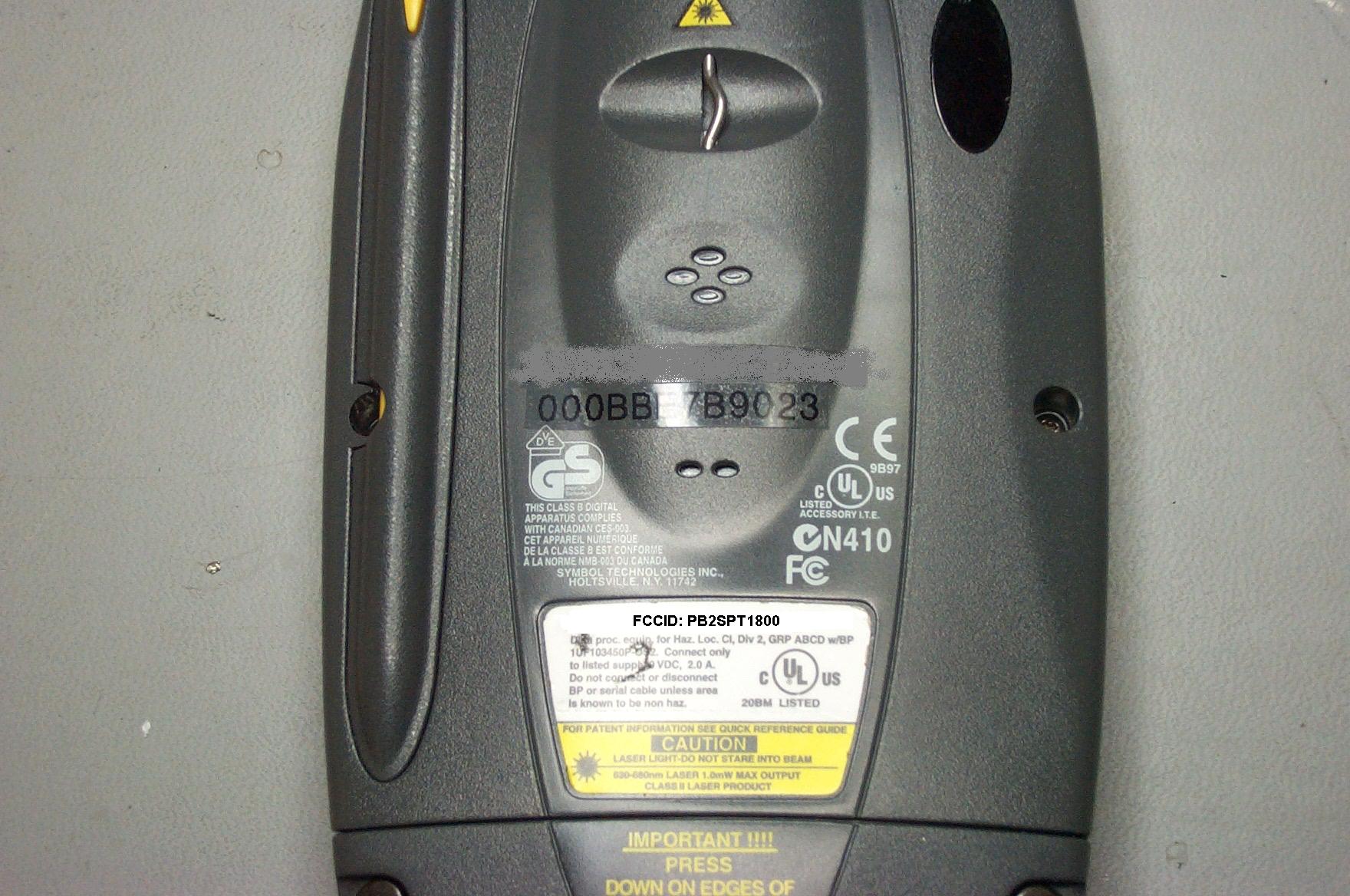
ID Label/Location Info
FCC ID: PB2SPT1800 Label Photo
Internal Photos
Antenna Bottom Antenna Front Antenna Side Antenna top
Internal Photos
Internal front Internal top
Operational Description
Federal Communications Commission Equipment Approval Services P.O. Box 358315 Pittsburgh, PA 15251-5315 RE: FCC Part 15 Certification of WAV ChameleonRF SPT1800 hand held data terminal FCCID: PB2SPT1800 Date: September 11, 2003 To The Commission: For the Operational Description of the AIR-LMC352 (FCCID: LDK102040) Spread Spectrum Transmitter, please refer to the original Cisco filing on 06/05/2000. If there are any questions about this request, please contact me at the number below. Thank you for your attention. Respectfully submitted, Charles D. Bolvin Vice President of Technology WAV Inc. [email protected] 630-818-1006 Voice 630-818-4450 FAX
RF Exposure Info
SAR COMPLIANCE TESTING OF CISCO/AIRONET MODEL LDK102040 WIRELESS PC April 28, 2000 Submitted to: Mr. David A. Case NCE Senior Compliance Engineer Cisco Systems 3875 Embassy Parkway Akron, OH 44333 Submitted by: Om P. Gandhi Professor of Electrical Engineering University of Utah 50 S Central Campus Dr., Rm. 3280 Salt Lake City, UT 84112-9206 2 SAR COMPLIANCE TESTING OF CISCO/AIRONET MODEL LDK102040 WIRELESS PC I. Introduction The U.S. Federal Communications Commission (FCC) has adopted limits of human exposure to RF emissions from mobile and portable devices that are regulated by the FCC [1]. The FCC has also recently issued Supplement C (Edition 97-01) to OET Bulletin 65 defining both the measurement and the computational procedures that should be followed for evaluating compliance of mobile and portable devices with FCC limits for human exposure to radiofrequency emissions [2]. We have used the measurement procedure given in [2] to obtain peak 1-g SARs for the Cisco/Aironet Model LDK102040 Wireless PC. A photograph of this unit is shown in Fig. 1. As seen in Fig. 1, the RF antenna operating in the ISM frequency band 2412-2462 MHz is mounted at the back of the right-hand side of the keyboard. The Cisco/Aironet Model LDK102040 operates with a transmit power of up to 100 mW radiated from a printed patch antenna. Since the wireless PC may also be potentially placed on the lap where the RF antenna would be the closest to the body, a planar phantom model was used for all SAR measurements. II. The Tissue-Simulant Model The testing for the SAR distribution for the Cisco/Aironet Model LDK102040 Wireless PC was done with a planar rectangular box phantom model shown in Fig. 2. This box phantom of external dimensions 30 ∞ 50 cm is filled with a tissue-simulant fluid up to a depth of 15.5 cm. To maintain flatness of the plantom, the rectangular box is 2 made of acrylic (ε r = 2.56) of thickness 6.35 mm. The tissue-simulant fluid uses a composition developed at the University of Utah which consists of 62.0% water, 37.0% sugar and 1% HEC. For this composition, we have measured the dielectric properties using a Hewlett Packard (HP) Model 85070B Dielectric Probe in conjunction with HP Model 8720C Network Analyzer (50 MHz-20 GHz). The measured dielectric properties at the midband 3 frequency of 2450 MHz are as follows: ε r = 51.3 ± 1.7 and σ = 1.76 ± 0.07 S/m. From reference 3, we obtain the desired dielectric properties to simulate the muscle tissue to be ε r = 52.7 and σ = 1.74 S/m. Thus, the measured properties for the muscle-simulant fluid are close to the desired values. III. The Measured SAR Distributions The SAR distribution was determined using the automated SAR measurement system developed at the University of Utah [4]. As described in [4], this SAR measurement system has been validated using a number of wireless telephones at 835 and 1900 MHz, respectively. The highest SAR region was identified in the first instance by using a coarser sampling with a step size of 8.0 mm over three overlapping areas for a total scan area of 8.0 ∞ 9.6 cm. After identifying the region of the highest SAR, the SAR distribution was measured with a resolution of 2 mm in order to obtain the peak 1 cm 3 or 1-g SAR. The measured SAR distribution for the Cisco/Aironet Model LDK102040 Wireless PC operated in the maximum radiation mode (maximum radiated power of 100 mW) is given in Table 1. The peak 1-g SAR is determined to be 0.160 W/kg. IV. Comparison of the Data With FCC 96-326 Guidelines According to the FCC 96-326 Guidelines [1], the peak SAR for any 1-g of tissue should not exceed 1.6 W/kg. For the maximum radiated power condition, the Cisco/Aironet Model LDK102040 Wireless PC has been measured to give a peak 1-g SAR of 0.160 W/kg which is considerably smaller than 1.6 W/kg. 4 REFERENCES 1. Federal Communications Commission, "Guidelines for Evaluating the Environmental Effects of Radiofrequency Radiation," FCC 96-326, August 1, 1996. 2. K. Chan, R. F. Cleveland, Jr., and D. L. Means, "Evaluating Compliance With FCC Guidelines for Human Exposure to Radiofrequency Electromagnetic Fields," Supplement C (Edition 97-01) to OET Bulletin 65, December, 1997. Available from Office of Engineering and Technology, Federal Communications Commission, Washington D.C., 20554. 3. http://Sparc10.iroe.fi.cnr.it/tissprop/. 4. Q. Yu, O. P. Gandhi, M. Aronsson, and D. Wu, "An Automated SAR Measurement System for Compliance Testing of Personal Wireless Devices," IEEE Transactions on Electromagnetic Compatibility, Vol. 41(3), pp. 234-245, August 1999. 5 Table 1. The SARs measured for Cisco/Aironet Model LDK102040 Wireless PC. The SARs in W/kg are measured with a step size of 2 mm for the highest SAR region. 1-g SAR = 0.160 W/kg a. At depth of 1 mm 0.268 0.293 0.308 0.327 0.337 0.299 0.299 0.323 0.338 0.336 0.310 0.327 0.328 0.347 0.328 0.298 0.316 0.334 0.332 0.331 0.302 0.315 0.312 0.328 0.298 b. At depth of 3 mm 0.192 0.205 0.215 0.224 0.228 0.209 0.215 0.225 0.235 0.232 0.213 0.222 0.226 0.235 0.229 0.206 0.220 0.228 0.229 0.226 0.205 0.215 0.217 0.222 0.213 c. At depth of 5 mm 0.129 0.134 0.140 0.141 0.141 0.135 0.147 0.146 0.152 0.148 0.136 0.138 0.145 0.145 0.148 0.133 0.143 0.144 0.146 0.143 0.129 0.135 0.141 0.139 0.144 d. At depth of 7 mm 0.080 0.079 0.083 0.080 0.077 0.079 0.093 0.086 0.089 0.086 0.077 0.077 0.084 0.078 0.088 0.077 0.084 0.080 0.084 0.081 0.072 0.076 0.084 0.077 0.089 e. At depth of 9 mm 0.044 0.041 0.044 0.039 0.035 0.039 0.054 0.045 0.046 0.044 0.039 0.038 0.043 0.033 0.047 0.040 0.045 0.039 0.042 0.040 6 0.035 0.037 0.045 0.037 0.048 7 Fig. 1. Photograph of Cisco/Aironet Model LDK102040 Wireless PC with RF antenna inserted at the back on the right-hand side of the keyboard. 8 Fig. 2. Photograph of Cisco/Aironet Model LDK102040 Wireless PC mounted with its bottom pressed against the bottom of the planar tissue-simulant phantom.
Test Report
September 8, 2003 WAV, Inc. Attn: Mr. Chuck D. Bolvin 245 West Roosevelt Road Building 7, Suite 48 West Chicago, IL 60185 UL Reference: File MC1343, Project 03NK27735 Subject: EMC Test and Measurement Report for Model SPT1800 Dear Mr. Bolvin: We have provided with this letter your EMC Test Report for the above referenced model. The product was determined to comply with the requirements noted in the report. Please review the attached report and direct any questions or comments to me. Samples were returned following testing. We appreciate your interest in UL’s EMC Services, and encourage you to contact us in the future should you need EMC test services. This closes Project 03NK27735. Best regards, Reviewed by: Lou Madjarov (Ext 43957) Eric Parent EMC Sr. Project Engineer EMC Staff Engineering Associate International EMC Services International EMC Services UL International EMC Services 333 Pfingsten Road Northbrook, Illinois 60062-2096 (800) 873-8536 Fax No. (847) 272-8864 http://www.ul.com/emc/ FCC ID: PB2SPT1800 File MC1343 Project 03NK27735 Page 1 of 8 UL International EMC Services www.ul.com/emc (800) USE UL EMC EMC – TEST REPORT Issue Date: September 8, 2003 √ EMISSIONS IMMUNITY Test Report File No. : MC1343 Project No. : 03NK27735 Model / Type : Model SPT1800 Kind of Product : Wrist-worn data terminal with integrated Cisco Aironet AIR-LMC352 PCMCIA WLAN Module Applicant : WAV, Inc. Address : 245 West Roosevelt Road : Building 7, Suite 48 : West Chicago, IL 60185 Manufacturer : Same as Applicant Test Result : COMPLIANT This report without appendices consists of 9 pages. Appendix A contains test photos, Appendix B contains original test data, Appendix C contains sample calculations and Appendix D contains an Antenna Calibration Schedule. The data contained in this report reflects only the items tested in the configurations and mode of operations described. An attempt has been made to arrange the EUT, with the equipment provided, into a test configuration which maximizes the observed emissions of the EUT while simulating, as close as practical, a typical end-use installation. The photos and data provided in this report document that configuration. Underwriters Laboratories Inc. authorizes the above company to reproduce this report provided it is reproduced in its entirety. Underwriters Laboratories Inc. 333 Pfingsten Rd. Northbrook, IL 60062 Fax: (847) 272-8864 FCC ID: PB2SPT1800 File MC1343 Project 03NK27735 Page 2 of 8 UL International EMC Services www.ul.com/emc (800) USE UL EMC REPORT DIRECTORY SECTION TITLE GENERAL 1.0 General Product Description 1.1 Model Differences 1.2 Environmental Conditions in Test Lab 1.3 Calibration Details of Equipment Used for Measurement 1.4 EUT (Equipment Under Test) Configuration 1.5 Antenna Configuration 1.6 EUT Operating Mode 1.7 Device Modifications EMISSIONS 2.0 Emissions Test Regulations Radiated Electric Field Emissions IMMUNITY 3.0 Immunity Test Regulations CONCLUSION 4.0 General Remarks 4.1 Summary APPENDICIES A Test Setups (Photos, Diagrams and Drawings) B Test Data C Sample Calculations D Antenna Calibration Schedule FCC ID: PB2SPT1800 File MC1343 Project 03NK27735 Page 3 of 8 UL International EMC Services www.ul.com/emc (800) USE UL EMC 1.0 GENERAL PRODUCT DESCRIPTION The EUT is a wrist-worn data terminal with integrated Cisco Aironet AIR-LMC352 PCMCIA WLAN Module, FCC ID: LDK102040. 1.0.1 Equipment Mobility: Wrist-worn (portable) 1.0.2 Test Voltage and Frequency: Voltage (V) Frequency (Hz) 3.6V DC 1.1 MODEL DIFFERENCES Any other model(s) represented by the models tested in this investigation will be documented by the manufacturer. 1.2 ENVIRONMENTAL CONDITIONS IN TEST LAB Temperature: 20-25 °C Relative Humidity: 30-60% RH Atmospheric Pressure: 860-1060 mbar 1.3 CALIBRATION OF EQUIPMENT USED FOR MEASUREMENT All test equipment and test accessories are calibrated on a regular basis. The maximum time between calibrations is one year or what is recommended by the manufacturer, whichever is less. All test equipment calibrations are traceable to the National Institute of Standards and Technology (NIST), therefore, all test data recorded in this report is traceable to NIST. FCC ID: PB2SPT1800 File MC1343 Project 03NK27735 Page 4 of 8 UL International EMC Services www.ul.com/emc (800) USE UL EMC 1.4 EUT CONFIGURATION(s) See Appendix A for individual set-up configuration(s). In addition to the EUT, the following peripheral devices and/or cables were connected during the measurement: Device Manufacturer Model Serial # FCC ID EUT Symbol Technologies SPT1800 SA0040K11U PB2SPT1800 Modular Transmitter CISCO AIR-LMC352 VEM062807MW LDK102040 1.5 ANTENNA CONFIGURATIONS COVERED Antenna EUT Output Power Antenna Gain Total EIRP Exposure Category OMNI 20dBm (100mW) 0 dBi 20dBm (100mW) Hand Held 1.6 EUT OPERATING MODE(s) The equipment under test was operated during the measurements under the following conditions: Continuous operation. 1.7 DEVICE MODIFICATIONS The following modifications were necessary for compliance: None. FCC ID: PB2SPT1800 File MC1343 Project 03NK27735 Page 5 of 8 UL International EMC Services www.ul.com/emc (800) USE UL EMC 2.0 EMISSIONS TEST REGULATIONS 47 CFR Part 15 Subpart B: 2002 + ANSI C63.4 – 1992 The device was evaluated to 15.247 of CFR 47, Part 15 Since the EUT is identical to a previously certified device except as noted in Section 1.0, only a limited test program was required. Testing was covered / required as noted below: Test / Requirement CFR 47, Part 15 Reference Test Required Notes Conducted emission 15.207 Not Applicable EUT is battery-operated device with no provision for direct connection to AC mains. 6dB Bandwidth 15.247(a)(2)No Considered covered by tests performed on previously certified device. (Cisco) RF Conducted Peak Output Power 15.247(b) No Considered covered by tests performed on previously certified device. (Cisco) Reduced output if directional gain exceeds 6dBi 15.247(b)(3)No Considered covered by tests performed …
Text truncated - open the document above for the full version.
Test Report
FCC ID: LDK102040 MFA p0040008, d0050047 Date: May 31, 2000 Federal Communications Commission Via: Electronic Filing Attention: Authorization & Evaluation Division Applicant: Cisco Systems Inc Equipment: AIR-LMC350 FCC ID: LDK102040 FCC Rules: 15.247 and Confidentiality Gentlemen: On behalf of the Applicant, enclosed please find Application Form 731, Engineering Test Report and all pertinent documentation, the whole for approval of the referenced equipment as shown. Filing fees are attached. We trust the same is in order. Should you need any further information, kindly contact the writer who is authorized to act as agent. Sincerely yours, Morton Flom, P. Eng. enclosure(s) cc: Applicant MF/cvr FCC ID: LDK102040 MFA p0040008, d0050047 LIST OF EXHIBITS (FCCCERTIFICATION(TRANSMITTERS) - REVISED 9/28/98) APPLICANT: Cisco Systems Inc FCC ID: LDK102040 BY APPLICANT: 1. LETTER OF AUTHORIZATION 2. IDENTIFICATION DRAWINGS ID LABEL LOCATION INFO ATTESTATION STATEMENT(S) LOCATION OF COMPLIANCE STATEMENT 3. DOCUMENTATION: 2.1033(b) (3) USER MANUAL(S) (4) OPERATIONAL DESCRIPTION (5) BLOCK DIAGRAM (5) SCHEMATIC DIAGRAM (7) EXTERNAL PHOTOGRAPHS INTERNAL PHOTOGRAPHS PARTS LIST ACTIVE DEVICES 4. DRAFT SPECIFICATION INFORMATION 5. PARTS LIST/TUNE UP INFO BY M.F.A. INC. A. TESTIMONIAL & STATEMENT OF CERTIFICATION B. STATEMENT OF QUALIFICATIONS FCC ID: LDK102040 MFA p0040008, d0050047 Sub-part 2.1033(c): EQUIPMENT IDENTIFICATION FCC ID: LDK102040 NAMEPLATE DRAWING ATTACHED, EXHIBIT 1. LOCATION AS PER LABEL DRAWING(S) DATE OF REPORT May 31, 2000 SUPERVISED BY: Morton Flom, P. Eng. FCC ID: LDK102040 MFA p0040008, d0050047 THE APPLICANT HAS BEEN CAUTIONED AS TO THE FOLLOWING: 15.21 INFORMATION TO USER. The users manual or instruction manual for an intentional radiator shall caution the user that changes or modifications not expressly approved by the party responsible for compliance could void the user's authority to operate the equipment. 15.27(a) SPECIAL ACCESSORIES. Equipment marketed to a consumer must be capable of complying with the necessary regulations in the configuration in which the equipment is marketed. Where special accessories, such as shielded cables and/or special connectors are required to enable an unintentional or intentional radiator to comply with the emission limits in this part, the equipment must be marketed with, i.e. shipped and sold with, those special accessories. However, in lieu of shipping or packaging the special accessories with the unintentional or intentional radiator, the responsible party may employ other methods of ensuring that the special accessories are provided to the consumer, without additional charge. Information detailing any alternative method used to supply the special accessories for a grant of equipment authorization or retained in the verification records, as appropriate. The party responsible for the equipment, as detailed in § 2.909 of this chapter, shall ensure that these special accessories are provided with the equipment. The instruction manual for such devices shall include appropriate instructions on the first page of text concerned with the installation of the device that these special accessories must be used with the device. It is the responsibility of the user to use the needed special accessories supplied with the equipment. FCC ID: LDK102040 MFA p0040008, d0050047 TABLE OF CONTENTS RULE DESCRIPTION PAGE . Test Report 1 2.1033(c) General Information Required 2 . Standard Test Conditions and Engineering Practices 6 15.247(b). Maximum Peak Output Power 7 15.247(c). Out of Band Emissions 19 15.205. Restricted Bands Of Operation 26 15.247(a)(2). Allowed Occupied Bandwidth 39 15.247(d). Transmitter Power Density 49 15.247(e). Processing Gain (Summary) 49 FCC ID: LDK102040 MFA p0040008, d0050047 PAGE NO.1of53. Required information per ISO/IEC Guide 25-1990, paragraph 13.2: a) TEST REPORT b) Laboratory: (FCC: 31040/SIT) (Canada: IC 2044) M. Flom Associates, Inc. 3356 N. San Marcos Place, Suite 107 Chandler, AZ 85225 c) Report Number: d0050047 d) Client: Cisco Systems Inc. 3875 Embassy Parkway Akron, OH 44333 e) Identification: AIR-LMC350 FCC ID: LDK102040 Description: Unlicensed PCMCIA Direct Sequence Spread Spectrum Transceiver f) EUT Condition: Not required unless specified in individual tests. g) Report Date: May 31, 2000 EUT Received: April 14, 2000 h, j, k): As indicated in individual tests. i) Sampling method: No sampling procedure used. l) Uncertainty: In accordance with MFA internal quality manual. m) Supervised by: Morton Flom, P. Eng. n) Results: The results presented in this report relate only to the item tested. o) Reproduction: This report must not be reproduced, except in full, without written permission from this laboratory. FCC ID: LDK102040 MFA p0040008, d0050047 PAGE NO.2of53. LIST OF GENERAL INFORMATION REQUIRED FOR CERTIFICATION IN ACCORDANCE WITH FCC RULES AND REGULATIONS, VOLUME II, PART 2 AND TO 15.247 and Confidentiality Sub-part 2.1033 (c)(1): NAME AND ADDRESS OF APPLICANT: Cisco Systems Inc 170 West Tasman Drive San Jose, CA 95134-1706 MANUFACTURER: Applicant (c)(2): FCC ID: LDK102040 MODEL NO: AIR-LMC350 (c)(3): INSTRUCTION MANUAL(S): PLEASE SEE ATTACHED EXHIBITS (c)(4): TYPE OF EMISSION: (c)(5): FREQUENCY RANGE, MHz : 2412 to 2462 (c)(6): POWER RATING, Watts: 0.1 (conducted all channels, all bit rates) 0.355 (EIRP with Yagi) 0.132 (EIRP with Dipole) 0.117 (EIRP with Snap) Switchable Variable x N/A (c)(7): MAXIMUM POWER RATING, Watts: 1 Watt Conducted 15.203: ANTENNA REQUIREMENT : The antenna is permanently attached to the EUT The antenna uses a unique coupling x The EUT must be professionally installed The antenna requirement does not apply FCC ID: LDK102040 MFA p0040008, d0050047 PAGE NO.3of53. Subpart 2.1033(continued) (c)(8): VOLTAGES & CURRENTS IN ALL ELEMENTS IN FINAL R. F. STAGE, INCLUDING FINAL TRANSISTOR OR SOLID STATE DEVICE: COLLECTOR CURRENT, A = per manual COLLECTOR VOLTAGE, Vdc = per manual SUPPLY VOLTAGE, Vdc = 5 (…
Text truncated - open the document above for the full version.
Test Report
FCC ID: LDK102040 MFA p0080005, d0080082 PAGE NO.7 of 53. AMENDED August 22, 2000 NAME OF TEST: Maximum Peak Output Power SPECIFICATION: 47 CFR 15.247(b) SPEC. LIMIT:≤1 Watt peak (0.25 if <50 Hopping Channels) TEST EQUIPMENT: Attached MEASUREMENT DATA ANTENNA GAIN, dBi = 0 Snap On PEAK OUTPUT POWER, Watts = 0.0955 EIRP WORST CASE FOR ALL CHANNELS NAME OF TEST: Radiated Emissions g0080488: 2000-Aug-17 Thu 14:16:00 Snap On Antenna FREQUENCY TUNED, MHz FREQUENCY EMISSION, MHz METER, dBuV CF, dB uV/m @ 3m EIRP, dBm EIRP, mw 2412.000000 2413.200000 59.06 55.77 551442.2 19.6 91.2 2442.000000 2443.300000 59.06 55.96 563637.66 19.8 95.5 2462.000000 2463.300000 57.94 56.1 503500.61 18.8 75.9 SUPERVISED BY: Morton Flom, P. Eng. FCC ID: LDK102040 MFA p0080005, d0080082 PAGE NO.9.1 of 53. AMENDED August 22, 2000 NAME OF TEST: Out of Band Emissions g0080487: 2000-Aug-17 Thu 11:10:00 Snap On Antenna FREQUENCY TUNED, MHz FREQUENCY EMISSION, MHz METER, dBuV CF, dB uV/m @ 3m EIRP, dBm MARGIN, dB 2442.000000 30.213000 11.93 14.87 21.88 -68.4 -13.2 2442.000000 34.000000 10.13 14.33 16.71 -70.8 -15.5 2442.000000 38.000000 17.61 13.83 37.33 -63.8 -8.6 2442.000000 42.000000 15.85 13.23 28.44 -66.1 -10.9 2442.000000 46.000000 -0.6 12.54 3.95 -83.3 -28.1 2442.000000 50.120000 11.04 11.88 14 -72.3 -17.1 2442.000000 54.000000 3.73 11.23 5.6 -80.3 -25 2442.000000 58.000000 -2.16 10.6 2.64 -86.8 -31.6 2442.000000 66.000000 -0.5 9.68 2.88 -86 -30.8 2442.000000 69.940000 2.99 9.31 4.12 -82.9 -27.7 2442.000000 74.000000 5.13 9.05 5.12 -81 -25.8 2442.000000 83.000000 10.1 9.04 9.06 -76.1 -20.9 2442.000000 86.000000 18.49 9.38 24.75 -67.4 -12.1 2442.000000 110.000000 10.59 12.97 15.07 -71.7 -19.4 2442.000000 114.550000 15.21 13.37 26.85 -66.6 -14.4 2442.000000 118.000000 10.86 13.67 16.85 -70.7 -18.5 2442.000000 122.000000 7.24 13.9 11.4 -74.1 -21.9 2442.000000 126.000000 14.16 14.04 25.7 -67 -14.8 2442.000000 130.000000 13.58 14.19 24.46 -67.5 -15.2 2442.000000 134.000000 11.51 14.5 19.98 -69.2 -17 2442.000000 138.000000 9.02 14.8 15.52 -71.4 -19.2 2442.000000 142.000000 8.73 14.98 15.33 -71.5 -19.3 2442.000000 144.025000 17.39 15.01 41.69 -62.8 -10.6 2442.000000 146.025000 4.69 15.04 9.69 -75.5 -23.3 2442.000000 150.325000 12 15.09 22.62 -68.1 -15.9 2442.000000 161.950000 7.43 14.89 13.06 -72.9 -20.7 2442.000000 166.000000 6.6 14.82 11.78 -73.8 -21.6 2442…
Text truncated - open the document above for the full version.
Contact Information
Applicant
Charles D Bolvin(VP of Technology)
Technical Contact
WAV Inc.Charles D Bolvin
[email protected]630-818-1006
245 West Roosevelt Road · West Chicago, Illinois · United States
Non-Technical Contact
WAV Inc.Charles D Bolvin
[email protected]630-818-1006
Test Firm
UL LLCRick Titus
Technical Specifications
| # | Rule Parts | Frequency Range | Power Output |
|---|---|---|---|
| 1 | 15C | 2.41 GHz - 2.46 GHz | 100.00 mW |
Other Applications from Wav Inc.
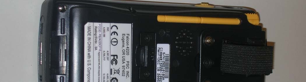
PB24220CF10
Nov 07, 2007Bar Code Scanner and WiFi Interface
Equipment Class
DTS - Digital Transmission System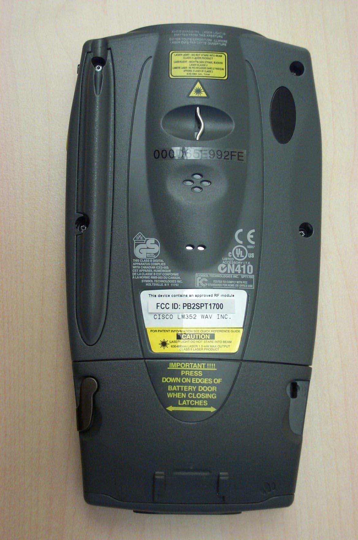
PB2SPT1700
Nov 17, 2003WAV ChameleonRF SPT1700
Equipment Class
DSS - Part 15 Spread Spectrum Transmitter
PB2WT2270
Apr 24, 2003Wrist-worn scanner transmitter
Equipment Class
DSS - Part 15 Spread Spectrum Transmitter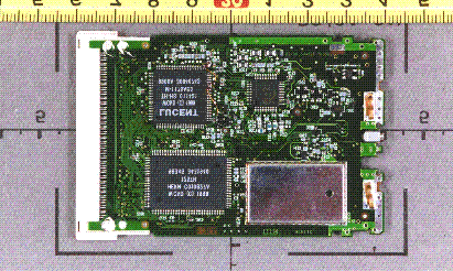
PB2WO80A
Mar 13, 2001Chameleon WLAN 80 Wireless LAN Adapter
Equipment Class
DSS - Part 15 Spread Spectrum Transmitter