PB2WT2270Wrist-worn scanner transmitter
Wav Inc.
Click to zoom
Application Details
- Equipment Class
- DSS - Part 15 Spread Spectrum Transmitter
- Date of Grant
- Apr 24, 2003
- Application Purpose
- Original Equipment
- Date of Application
- Mar 06, 2003
- Equipment Note
- Wrist-worn scanner transmitter
- Frequency Range
- 2412.00000000 - 2462.00000000
- Company
- Wav Inc.
- Country
- United States
Documents & Files
Document Text
Text extracted from the exhibit documents filed with the FCC. Open a document above to read the original.
Users Manual
PLANNED STATEMENTS FOR MANUAL USA – Federal Communications Commission (FCC) Interference Statement This device complies with Part 15 of the FCC Rules. Operation is subject to the following to conditions: (1) this device may not cause harmful interference, and (2) this device must accept any interference received, including interference that may cause undesired operation. Information for the user This equipment has been tested and found to comply with the limits for a Class B digital device, pursuant to Part 15 of the FCC Rules. These limits are designed to provide reasonable protection against harmful interference in a residential installation. This equipment generates, uses and can radiate radio frequency energy. If not installed and used in accordance with the instructions, it may cause harmful interference to radio communications. However, there is no guarantee that interference will not occur in a particular installation. If this equipment does cause harmful interference to radio or television reception, which can be determined by turning the equipment off and on, the user is encouraged to try and correct the interference by one or more of the following measures: Reorient or relocate the receiving antenna. Increase the distance between the equipment and the receiver. Consult the dealer or an experienced radio/TV technician for help. RF Safety Statement For body worn operation, this equipment has been tested and meets FCC RF exposure guidelines when used WAV accessories supplied or designated for this product. Use of other accessories may not ensure compliance with FCC exposure guidelines. WAV Inc. is not responsible for any radio or television interference caused by unauthorized modification of the devices included with the WT2270 terminal or the substitution or attachment of connecting cable and equipment other than specified by WAV Inc. The correction of interference caused by such unauthorized modification, substitution or attachment will be the responsibility of the user.
Users Manual
Introduction The WT 2200 is a wearable data entry system consisting of a laser bar code scanner, usually worn on the operator’s fingers or back of hand, and a wrist computer worn on the operator’s forearm. The detachable components work equally well for right- and left-handed individuals. Detachable personal mounts allow multiple operators to share both scanner and wrist computer without having to use the same mount. About This Guide This guide presents information on system components, assembling the WT 2200, battery installation and charging, attaching the system, using the keyboard, and disassembly for use by others. For wearable scanner information, refer to the WT 2200 Product Reference Guide provided with your scanner. Parts of the WT 2200 System Keyboard Display Speaker Battery Latch Power Switch Battery Charging Contacts Lithium-Ion Battery WT 2200 Top WT 2200 (Wrist Computer) Front Adjustable Straps Snap-On Bar WT 2200 Wrist Mount Installing and Charging the Battery The wrist computer and scanner are powered by a Lithium- Ion battery pack. The pack provides power for a typical 8- hour shift. Note: Before using the wrist computer, install and fully charge the Lithium-Ion battery pack. To install the battery pack in the WT 2200: 1. Insert the battery pack, base first, in the battery compartment. 2. Line up the pack’s locking mechanism with the notch in the battery compartment wall by sliding the battery latch, and press the pack into place. 3. Release the battery latch to lock in place. Battery Latch Notch Battery Compartment Battery Pack Base Charging the Battery in WT 2200 To charge the Lithium-Ion battery in the WT 2200: 1. Place the WT 2200 in the cradle as shown below: 2. The cradle’s CHARGING light illuminates (RED) if the WT 2200 is properly seated and the battery is charging. 3. The battery requires approximately 2 hours to charge fully. The CHARGING light changes to GREEN when the battery is fully charged. 4. To remove the WT 2200 from the cradle, tilt the WT 2200 upward and pull out. For more information on the CS 1000 Cradle, refer to the CS 1000 Single-Slot Cradle QRG, p/n 70-16237- xx, or the CS 1000 4-Slot Cradle QRG, p/n 70-17661- xx. Charging the Spare Battery Spare battery packs can be charged separate from the WT 2200. To charge a spare battery pack in the cradle: 1. Insert the pack in the cradle’s spare charging slot. 2. The CHARGING light illuminates red. 3. The spare pack is charged in approximately two hours, even if the WT 2200 is charging at the same time. The CHARGING light changes to green when the battery is fully charged. Assembling the WT 2200 System To assemble the WT 2200 (wrist computer): 1. Place the WT 2200 wrist computer onto the wrist mount, facing you. Be sure the mount is oriented so that the longer strap will be further up the forearm. 2. Snap the bar over the WT 2200 using the snaps on either side of the mount. The straight part of the bar should lay across the front of the WT 2200; the curved part in back. Note: The snaps on the wrist mount act as a tear-away device allowing the wrist computer to detach from the mount if it catches on an object. 2. Plug the cable connector from the WT 2200 in the interface port on the back of the scanner. 2. Place the WT 2200 on your arm: a. Slide the wrist mount on your arm, so that the WT 2200 wrist computer faces you. Pull the straps through the buckles so the wrist mount is secure but not tight. a. Use the Velcro to secure the straps. 2. Assemble and mount your scanner. Power Once the battery pack is fully charged, you are ready to use the wrist computer. To power the wrist computer on, press the power switch on top of the WT 2200. Display Light and Contrast To turn the display light and keypad backlight on, press LAMP (Left Alpha and Help). To adjust the contrast: • press FUNC and SPACE to darken the contrast, • press FUNC and BKSP to lighten the contrast. Communicating with the Host Using the Cradle The CS 1000 cradle is used to perform communications with a host PC. To set up the cradle for operation: 1. Plug one end of a null modem cable (p/n 59846-03-00) into the communications port located on the left end of the cradle. 2. Connect the other end of the cable to the host computer’s serial (COMM) port. 3. Provide power to the cradle by plugging the power supply’s round connector into the power port on the cradle and the other end of the power cable in an electrical outlet. 4. Insert the WT 2200 in the cradle (the ring scanner can be attached). 5. Start the communications program as detailed in the WT 2200 Product Reference Guide. Radio Communications Wireless communication with the host is available through the ChameleonRF _ IEEE 802.11b radio network. For information on performing radio communications, refer to the WT 2200 Product Reference Guide. Data Entry Using the Keyboard The keyboard consists of two types of keys: alphanumeric character keys and modifier keys. Most keys are self- explanatory. Some guidelines for using the keyboard include: • Press keys one at a time. Pressing two keys simultaneously produces an error. • The default keyboard produces numbers; to produce letters, press the left Alpha Shift and the appropriate key to produce the letters in purple, and the right Alpha Shift to produce the letters in green, as shown below. • Use the modifier keys, FUNC, SHIFT, and CTRL, in combination with the character keys to produce other characters or to issue commands. Refer to documentation for your application for more information. Cursor position is controlled by the Up Arrow, Down Arrow, Left Arrow, and Right Arrow keys. Removing the WT 2200 from the Alpha Shift Right Alpha Shift Left Alpha Shift Mount The WT 2200 can be removed from the wrist mount for use by other operators. To remove the WT 2200: 1. Detach the cable connection to the scanner. 2. Unsnap the bar securing the wrist computer. 3. Lift the WT 2200 out of the mount. Cleaning Wrist Computer To clean the wrist computer, use a cl…
Text truncated - open the document above for the full version.
Users Manual
TAKE OUT WHAT YOU NEED INSTALL THE PC CARD CLIENT ADAPTER INSTALL THE APPROPRIATE DRIVER AND UTILITIES 1 2 3 Quick Start Guide CISCO AIRONET 350 SERIES PC CARD C LIENT ADAPTERS Laptops with PC card client adapters Access Point 1 Take Out What You Need If any item is missing or damaged, contact your Cisco representative or reseller for support. Note: The integrated antenna on PC models of the Aironet PC Client Card Adapter is permanently attached; LM models are shipped with no antenna. Additional Requirements •A computing device (desktop personal computer, notebook, laptop computer, portable or hand-held device) equipped with an internal or external PC Card Type II or Type III slot. All drivers and supporting software (card and socket services) for the PC card slot must be loaded and configured. •The following information from your system administrator: —your wireless client name —the (case-sensitive) wireless service set identification (SSID) for your radio network —for Microsoft Windows networking, your computer name and workgroup name —the username and password for your network account —if you are not connected to a DHCP server, the IP address, default gateway address, and subnet mask of your computer —for Windows NT systems, an available IRQ number (interrupt address) in your system Cisco Aironet 350 Series PC Card Client Adapter (labeled Wireless LAN Adapter) Cisco Aironet 350 Series PC Card Client Adapter CDs for Windows 95 and Windows NT or Windows 98 and Windows 2000 with software and product documentation CISCO AIRONET 340 SERIES 11 Mbps WIRELESS LAN ADAPTER 2 Install the PC Card Client Adapter CautionThe following procedures and physical connections apply generally to normal and conventional PC card slots. In cases of custom or non-conventional equipment, be alert to possible differences in PC card slot configurations. 1 Before you begin, examine the PC card client adapter. One end is a dual-row, 68-pin PC card connector. The card is keyed so that it can be inserted only one way into the PC card slot. The slot in your computing device must be a PC card Type II slot (this includes slots that support both the Type II and Type III cards). Note: The PC card slot will be on the left or right side of the computer, depending on the model. 2 For Windows 95 and Windows 98 systems, remove any other PC card from the card slot. 3 For Windows 95 or Windows 98 systems, turn the computer on before inserting the PC card client adapter. For Windows NT systems, turn the computer off before inserting the client adapter. CautionNever force the PC card client adapter into the PC card slot. Forcing it will damage both the PC card and the slot. If the PC card does not easily insert, remove the card and re-insert it. 4 Hold the PC card client adapter with the logo facing up and insert the card into the slot, applying just enough pressure to make sure it is fully seated. Proceed to the appropriate driver installation for your operating system. 3 Note: The following procedures assume you are installing the driver from the CD provided. If your PC does not have a CD-ROM drive, download the driver from Cisco’s web site. Install the Appropriate Driver and Utilities Windows 98 Systems Note: The Windows 98 driver also works with the Windows 2000 operating system. In Windows 98 systems, after you have installed the PC card client adapter, the system automatically detects it, opens a New Hardware Found window, and starts collecting information for a driver database. 1 When the Add New Hardware Wizard dialog box opens, it is searching for new drivers. Click Next. 2 From the next dialog box, select Search for the best driver for your device (Recommended) and click Next. 3 Select CD-ROM drive, deselect all other options, insert the Cisco Aironet 350 Series Client Adapter CD for Windows 98, and click Next. 4 The hardware wizard will find the installation files on the CD and display the search results. When the PCMCIA adapter driver is displayed, click Next to copy the required files. 5 During driver installation, you may be prompted to enter a path to the required client adapter or Windows 98 files: (a) Windows 98 files installed on your PC are usually located in the folder C:\Windows\Options\Cabs. Click OK to install. (b) If the system prompts you for the Windows CD and the CD-ROM drive on your PC is drive D, the path should be D:\WIN98. Click OK to copy the required files. 6 The Add New Hardware Wizard window again opens indicating that the installation is complete. Click Finish. 7 Remove the CD and restart your laptop. 8 When the computer restarts, double-click My Computer, Control Panel, and Network. 9 Select the PCMCIA adapter and click Properties. 10 In the Properties window, click Advanced. 11 In the Advanced window, select Client Name and enter your computer’s unique name in the Value dialog box. 12 Select SSID. Enter your Access Point’s (case-sensitive) SSID in the Value dialog box. Click OK. 4 13 If you are not connected to a DHCP server, double-click My Computer, Control Panel, and Network. Click the Protocols tab and select TCP/IP and Properties. Select Specify an IP address and enter the IP Address, Subnet Mask, and Default Gateway address of your computer. Click OK. 14 In the Network window, click OK. 15 When prompted, click Ye s to reboot the laptop. Windows 95 Systems In Windows 95 systems, after you have installed the PC card client adapter, the system automatically detects it, opens a New Hardware Found window, and starts collecting information for a driver database. 1 The Update Device Driver Wizard dialog box opens and indicates that Windows will complete the installation of the PCMCIA adapter. 2 Insert the Client Adapter CD for Windows 95 and NT, and click Next. 3 When the Update Device Driver Wizard indicates that it is unable to locate a driver, click Other Locations. 4 In the Select other Location window, click Browse. 5 Select the CD-ROM drive and click OK. 6 In the Select other Location win…
Text truncated - open the document above for the full version.
Users Manual
Introduction The WT 2200 is a wearable data entry system consisting of a laser bar code scanner, usually worn on the operator’s fingers or back of hand, and a wrist computer worn on the operator’s forearm. The detachable components work equally well for right- and left-handed individuals. Detachable personal mounts allow multiple operators to share both scanner and wrist computer without having to use the same mount. About This Guide This guide presents information on system components, assembling the WT 2200, battery installation and charging, attaching the system, using the keyboard, and disassembly for use by others. For wearable scanner information, refer to the WT 2200 Product Reference Guide provided with your scanner. Parts of the WT 2200 System Keyboard Display Speaker Battery Latch Power Switch Battery Charging Contacts Lithium-Ion Battery WT 2200 Top WT 2200 (Wrist Computer) Front Adjustable Straps Snap-On Bar WT 2200 Wrist Mount Installing and Charging the Battery The wrist computer and scanner are powered by a Lithium- Ion battery pack. The pack provides power for a typical 8- hour shift. Note: Before using the wrist computer, install and fully charge the Lithium-Ion battery pack. To install the battery pack in the WT 2200: 1. Insert the battery pack, base first, in the battery compartment. 2. Line up the pack’s locking mechanism with the notch in the battery compartment wall by sliding the battery latch, and press the pack into place. 3. Release the battery latch to lock in place. Battery Latch Notch Battery Compartment Battery Pack Base Charging the Battery in WT 2200 To charge the Lithium-Ion battery in the WT 2200: 1. Place the WT 2200 in the cradle as shown below: 2. The cradle’s CHARGING light illuminates (RED) if the WT 2200 is properly seated and the battery is charging. 3. The battery requires approximately 2 hours to charge fully. The CHARGING light changes to GREEN when the battery is fully charged. 4. To remove the WT 2200 from the cradle, tilt the WT 2200 upward and pull out. For more information on the CS 1000 Cradle, refer to the CS 1000 Single-Slot Cradle QRG, p/n 70-16237- xx, or the CS 1000 4-Slot Cradle QRG, p/n 70-17661- xx. Charging the Spare Battery Spare battery packs can be charged separate from the WT 2200. To charge a spare battery pack in the cradle: 1. Insert the pack in the cradle’s spare charging slot. 2. The CHARGING light illuminates red. 3. The spare pack is charged in approximately two hours, even if the WT 2200 is charging at the same time. The CHARGING light changes to green when the battery is fully charged. Assembling the WT 2200 System To assemble the WT 2200 (wrist computer): 1. Place the WT 2200 wrist computer onto the wrist mount, facing you. Be sure the mount is oriented so that the longer strap will be further up the forearm. 2. Snap the bar over the WT 2200 using the snaps on either side of the mount. The straight part of the bar should lay across the front of the WT 2200; the curved part in back. Note: The snaps on the wrist mount act as a tear-away device allowing the wrist computer to detach from the mount if it catches on an object. 2. Plug the cable connector from the WT 2200 in the interface port on the back of the scanner. 2. Place the WT 2200 on your arm: a. Slide the wrist mount on your arm, so that the WT 2200 wrist computer faces you. Pull the straps through the buckles so the wrist mount is secure but not tight. a. Use the Velcro to secure the straps. 2. Assemble and mount your scanner. Power Once the battery pack is fully charged, you are ready to use the wrist computer. To power the wrist computer on, press the power switch on top of the WT 2200. Display Light and Contrast To turn the display light and keypad backlight on, press LAMP (Left Alpha and Help). To adjust the contrast: • press FUNC and SPACE to darken the contrast, • press FUNC and BKSP to lighten the contrast. Communicating with the Host Using the Cradle The CS 1000 cradle is used to perform communications with a host PC. To set up the cradle for operation: 1. Plug one end of a null modem cable (p/n 59846-03-00) into the communications port located on the left end of the cradle. 2. Connect the other end of the cable to the host computer’s serial (COMM) port. 3. Provide power to the cradle by plugging the power supply’s round connector into the power port on the cradle and the other end of the power cable in an electrical outlet. 4. Insert the WT 2200 in the cradle (the ring scanner can be attached). 5. Start the communications program as detailed in the WT 2200 Product Reference Guide. Radio Communications Wireless communication with the host is available through the ChameleonRF _ IEEE 802.11b radio network. For information on performing radio communications, refer to the WT 2200 Product Reference Guide. Data Entry Using the Keyboard The keyboard consists of two types of keys: alphanumeric character keys and modifier keys. Most keys are self- explanatory. Some guidelines for using the keyboard include: • Press keys one at a time. Pressing two keys simultaneously produces an error. • The default keyboard produces numbers; to produce letters, press the left Alpha Shift and the appropriate key to produce the letters in purple, and the right Alpha Shift to produce the letters in green, as shown below. • Use the modifier keys, FUNC, SHIFT, and CTRL, in combination with the character keys to produce other characters or to issue commands. Refer to documentation for your application for more information. Cursor position is controlled by the Up Arrow, Down Arrow, Left Arrow, and Right Arrow keys. Removing the WT 2200 from the Alpha Shift Right Alpha Shift Left Alpha Shift Mount The WT 2200 can be removed from the wrist mount for use by other operators. To remove the WT 2200: 1. Detach the cable connection to the scanner. 2. Unsnap the bar securing the wrist computer. 3. Lift the WT 2200 out of the mount. Cleaning Wrist Computer To clean the wrist computer, use a cl…
Text truncated - open the document above for the full version.
Cover Letter(s)
Federal Communications Commission Equipment Approval Services P.O. Box 358315 Pittsburgh, PA 15251-5315 RE: FCC Part 15 Certification of WAV ChameleonRF WT2270 wrist worn data terminal FCCID: PB2WT2270 Date: March 7, 2003 To The Commission: This certification request is for the WAV ChameleonRF Model WT2270 portable terminal with integrated Cisco Aironet AIR-LMC352 PCMCIA WLAN Module. The WT2270 is a wrist worn device and has been subjected to SAR verification. The test report is included in this filing. The Cisco Aironet AIR-LMC352 wireless LAN PCMCIA adapter has previously been FCC certified under FCCID LDK102040. Form 159 has been electronically paid via credit card. If there are any questions about this request, please contact me at the number below. Thank you for your attention. Respectfully submitted, Charles D. Bolvin Vice President of Technology WAV Inc. [email protected] 630-818-1006 Voice 630-818-4450 FAX
Cover Letter(s)
Federal Communications Commission Equipment Approval Services P.O. Box 358315 Pittsburgh, PA 15251-5315 RE: FCC Part 15 Certification of WAV ChameleonRF WT2270 wrist worn data terminal FCCID: PB2WT2270 Date: March 23, 2003 To The Commission: To acknowledge the communication from the Commission on March 19, 2003, Reference Number 24975 indicating the FCC Label should be modified to appear on a single line. I have uploaded to the filing site a new label that should satisfy this requirement. If there are any questions about this request, please contact me at the number below. Thank you for your attention. Respectfully submitted, Charles D. Bolvin Vice President of Technology WAV Inc. [email protected] 630-818-1006 Voice 630-818-4450 FAX
Cover Letter(s)
CISCO CONFIDENTIALMercury processing gainJ. Friedmann data ratesmodulation usedsymbol rateschip ratechip per bit 10 log (chip per bit) add 3dB if unique codes for I & Q (minus 1 dB for implementation) theoretical processing gain dB (add last two columns) measured processing gain 1 mb/sBPSK1 mbps11 mbps 11 (same code for I & Q)10.7 dB10.7 dB10.8 dB 2 mb/sQPSK1 mbps11 mbps 11 (same code for I & Q)10.7 dB10.7 dB10.8 dB 5.5 mb/sCCK1.375 mbps8 mbps 8 (8 for I & 8 for Q)9 dB2 dB11 dB10.7 dB 11 mb/sCCK1.375 mbps8 mbps 8 (8 for I & 8 for Q)9 dB2 dB11 dB10.6 dB 9/25/001PG_Mercury_th_writeup.xls
Cover Letter(s)
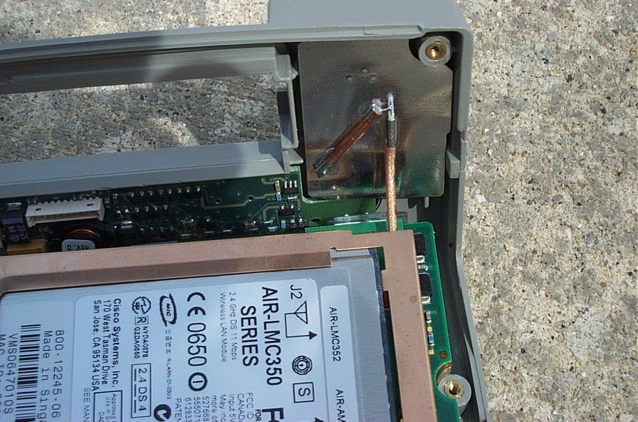
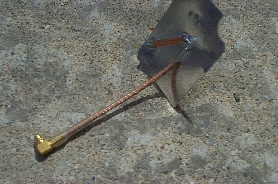
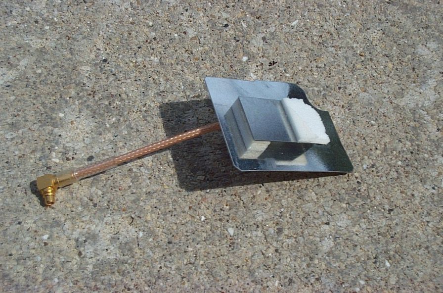
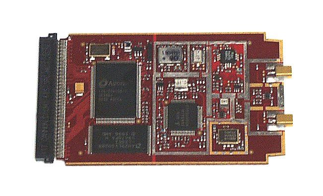
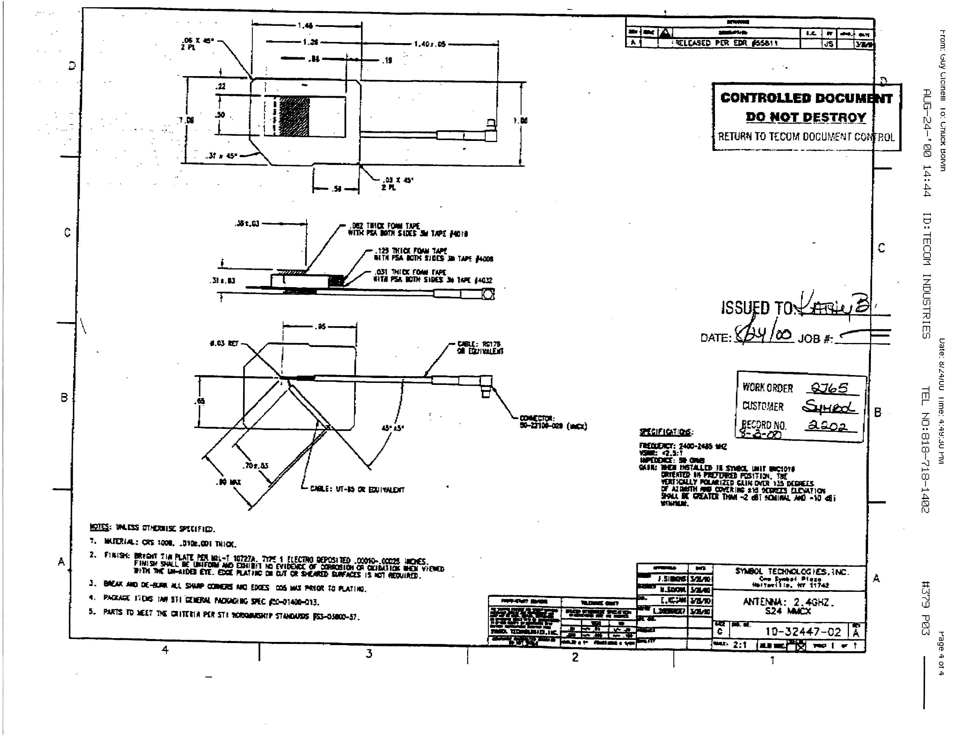
Federal Communications Commission Application Processing Branch RE: Correspondence Reference Number 25051 FCCID: PB2WT2270 Date: April 15, 2003 To: Stan Style Acknowledging your communication on April 11, 2003, Reference Number 25051. 1. This particular antenna was not approved under the original Cisco filing. We tested it under the pending application. 2. This is obviously in error. I don’t know how the reference to 960 Mhz to 15 Mhz appeared in form 731. It should be 2412.0 Mhz to 2462.0 Mhz at 100mW conducted as stated in the SAR report. 3. I have uploaded the Cisco filing documents as requested. 4. A photo of the antenna alone and installed in the terminal has been uploaded. 5. A full manual with RF Safety information has been uploaded. If there are any questions about this request, please let me know. Thank you for your attention. Charles D. Bolvin Vice President of Technology WAV Inc. [email protected] 630-818-1006 Voice 630-818-4450 FAX
Cover Letter(s)
Federal Communications Commission Application Processing Branch RE: Correspondence Reference Number 25067 FCCID: PB2WT2270 731 Confirmation Number EA451762 Date: April 17, 2003 To: Stan Lyles Acknowledging your communication on April 17, 2003, Reference Number 25067. We included the following text on Page 29 of the User Manual, which was uploaded to the site on April 15 th . The equipment has am internal antenna and there is no way to alter the distance away from the body if the wrist mount is used properly. We were of the opinion that this was sufficient. If this is not acceptable is there an alternate text you can suggest? RF Safety Statement For body worn operation, this equipment has been tested and meets FCC RF exposure guidelines when used WAV accessories supplied or designated for this product. Use of other accessories may not ensure compliance with FCC exposure guidelines. This equipment is designed to be worn on the operator’s wrist. Modification of the wrist mount for use on any other part of the body may violate FCC Exposure Guidelies. See “Assembling The WT2200 System” for the proper procedure. Thank you for your attention. Charles D. Bolvin Vice President of Technology WAV Inc. [email protected] 630-818-1006 Voice 630-818-4450 FAX
Cover Letter(s)
Federal Communications Commission Application Processing Branch RE: Correspondence Reference Number 25068 FCCID: PB2WT2270 731 Confirmation Number EA451762 Date: April 12, 2003 To: Stan Lyles Acknowledging your communication on April 18, 2003, Reference Number 25068. We will include the following text in the user manual: "If not wearing the device on the wrist as prescribed above please always maintain a separation distance of at least 1 cm from your body to the antenna which is located in the area just above the beeper opening and next to the battery lock" Thank you for your attention. Charles D. Bolvin Vice President of Technology WAV Inc. [email protected] 630-818-1006 Voice 630-818-4450 FAX
Cover Letter(s)
Federal Communications Commission Application Processing Branch RE: Correspondence Reference Number 25091 FCCID: PB2WT2270 731 Confirmation Number EA451762 Date: April 24, 2003 To: Stan Lyles Acknowledging your communication on April 24, 2003, Reference Number 25091. The WT2270 does not operate with an AC adapter. The only external power input is for battery charging which requires the unit to be removed from the body and placed in a charging cradle. Thank you for your attention. Charles D. Bolvin Vice President of Technology WAV Inc. [email protected] 630-818-1006 Voice 630-818-4450 FAX
External Photos
Federal Communications Commission Equipment Approval Services P.O. Box 358315 Pittsburgh, PA 15251-5315 RE: FCC Part 15 Certification of WAV ChameleonRF WT2270 wrist worn data terminal FCCID: PB2WT2270 Date: March 7, 2003 To The Commission: The following items are included in the SAR test reports: 1. External Photos If there are any questions about this request, please contact me at the number below. Thank you for your attention. Respectfully submitted, Charles D. Bolvin Vice President of Technology WAV Inc. [email protected] 630-818-1006 Voice 630-818-4450 FAX
ID Label/Location Info
FCC LABEL: FCCID: PB2WT2270
ID Label/Location Info
FCC LABEL: FCCID:PB2WT2270
Internal Photos
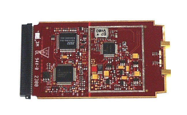
PB2WT2270 Internal Photographs
Operational Description
Federal Communications Commission Equipment Approval Services P.O. Box 358315 Pittsburgh, PA 15251-5315 RE: FCC Part 15 Certification of WAV ChameleonRF WT2270 wrist worn data terminal FCCID: PB2WT2270 Date: March 7, 2003 To The Commission: For the Operational Description of the AIR-LMC352 (FCCID: LDK102040) Spread Spectrum Transmitter, please refer to the original Cisco filing on 06/05/2000. If there are any questions about this request, please contact me at the number below. Thank you for your attention. Respectfully submitted, Charles D. Bolvin Vice President of Technology WAV Inc. [email protected] 630-818-1006 Voice 630-818-4450 FAX
Parts List/Tune Up Info
BOM-200-004994 This document includes the followin g assembl y variations: Variation Title Descri p tion -002 5V, A PHY, REV. A0 BDS. ONLY -006 5V, A PHY, LED MOD, PCI MOD -008 5V, B PHY, LED MOD, PCI MOD 05-May-00 BOM-200-004994 PAGE 1 OF 4 RUN PRODUCT ASSEMBLY , PLUTO LM SERIES RADIO BILL OF MATERIALS THE INFORMATION CONTAINED HEREIN IS PROPRIETARYANY REPRODUCTION OR DISCLOSURE OF THIS DRAWN: Julie Hawk APPROVAL: Jim Friedmann 01-May-00 CHECKED: DOCUMENT IS FORBIDDEN, EXCEPT WITH WRITTENTO AIRONET WIRELESS COMMUNICATIONS INC.PERMISSION FROM AIRONET WIRELESS COMMUNICATIONS. REV DESCRIPTION ECN A1 2382 INCORPORATED ECN REVISIONS A PPROVED Aironet Wireless Communications, Inc. Fairlawn, Ohio 44333 h a a a a NOTE: SEE SOURCE CONTROL DRAWINGS FOR ORDERING INFORMATION. Part Number Value/Item Description Reference Designator Rev Item Qty Fab Assy -002: 5V, A PHY, REV. A0 BDS. ONLY Doc Cell TESTED MECH. ASSY , PLUTO LM SERIES RADIO 5V , A PHY 421-004994-002 1 1 05-May-00 BOM-200-004994 PAGE 2 OF 4 RUN PRODUCT ASSEMBLY , PLUTO LM SERIES RADIO BILL OF MATERIALS THE INFORMATION CONTAINED HEREIN IS PROPRIETARYANY REPRODUCTION OR DISCLOSURE OF THIS DRAWN: Julie Hawk APPROVAL: Jim Friedmann 01-May-00 CHECKED: DOCUMENT IS FORBIDDEN, EXCEPT WITH WRITTENTO AIRONET WIRELESS COMMUNICATIONS INC.PERMISSION FROM AIRONET WIRELESS COMMUNICATIONS. REV DESCRIPTION ECN A1 2382 INCORPORATED ECN REVISIONS A PPROVED Aironet Wireless Communications, Inc. Fairlawn, Ohio 44333 h a a a a NOTE: SEE SOURCE CONTROL DRAWINGS FOR ORDERING INFORMATION. Part Number Value/Item Description Reference Designator Rev Item Qty Fab Assy -006: 5V, A PHY, LED MOD, PCI MOD Doc Cell TESTED MECH. ASSY , PLUTO LM SERIES RADIO 5V , A PHY , LED MOD , PCI M 421-004994-006 1 1 05-May-00 BOM-200-004994 PAGE 3 OF 4 RUN PRODUCT ASSEMBLY , PLUTO LM SERIES RADIO BILL OF MATERIALS THE INFORMATION CONTAINED HEREIN IS PROPRIETARYANY REPRODUCTION OR DISCLOSURE OF THIS DRAWN: Julie Hawk APPROVAL: Jim Friedmann 01-May-00 CHECKED: DOCUMENT IS FORBIDDEN, EXCEPT WITH WRITTENTO AIRONET WIRELESS COMMUNICATIONS INC.PERMISSION FROM AIRONET WIRELESS COMMUNICATIONS. REV DESCRIPTION ECN A1 2382 INCORPORATED ECN REVISIONS A PPROVED Aironet Wireless Communications, Inc. Fairlawn, Ohio 44333 h a a a a NOTE: SEE SOURCE CONTROL DRAWINGS FOR ORDERING INFORMATION. Part Number Value/Item Description Reference Designator Rev Item Qty Fab Assy -008: 5V, B PHY, LED MOD, PCI MOD Doc Cell TESTED MECH. ASSY , PLUTO LM SERIES RADIO 5V , B PHY , LED MOD , PCI M 421-004994-008 1 1 05-May-00 BOM-200-004994 PAGE 4 OF 4 RUN PRODUCT ASSEMBLY , PLUTO LM SERIES RADIO BILL OF MATERIALS THE INFORMATION CONTAINED HEREIN IS PROPRIETARYANY REPRODUCTION OR DISCLOSURE OF THIS DRAWN: Julie Hawk APPROVAL: Jim Friedmann 01-May-00 CHECKED: DOCUMENT IS FORBIDDEN, EXCEPT WITH WRITTENTO AIRONET WIRELESS COMMUNICATIONS INC.PERMISSION FROM AIRONET WI…
Text truncated - open the document above for the full version.
Contact Information
Applicant
Charles D Bolvin(VP of Technology)
Test Firm
UL LLCRick Titus
Technical Specifications
| # | Rule Parts | Frequency Range | Power Output |
|---|---|---|---|
| 1 | 15C | 2.41 GHz - 2.46 GHz | 100.00 mW |
Other Applications from Wav Inc.
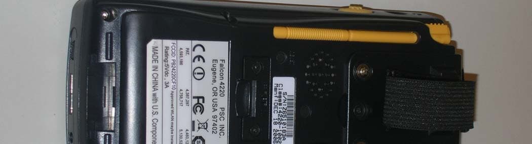
PB24220CF10
Nov 07, 2007Bar Code Scanner and WiFi Interface
Equipment Class
DTS - Digital Transmission System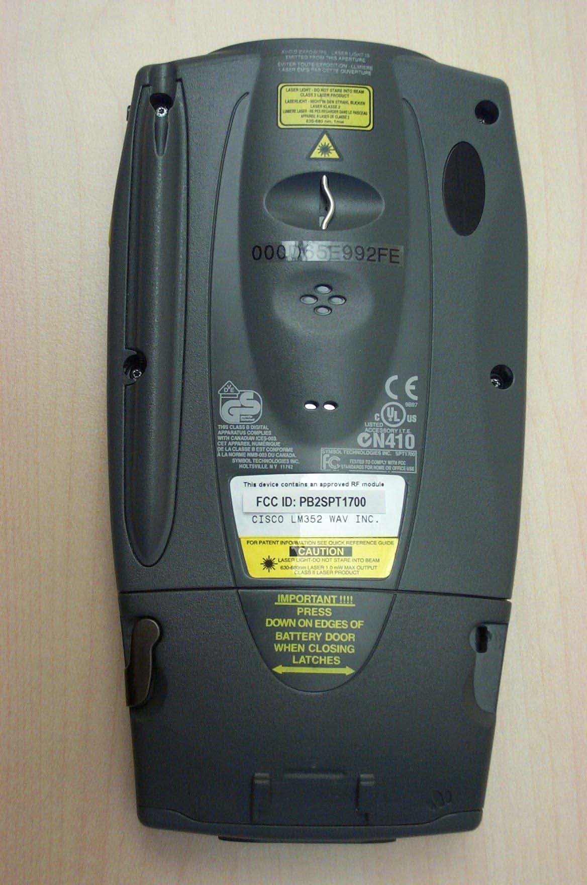
PB2SPT1700
Nov 17, 2003WAV ChameleonRF SPT1700
Equipment Class
DSS - Part 15 Spread Spectrum Transmitter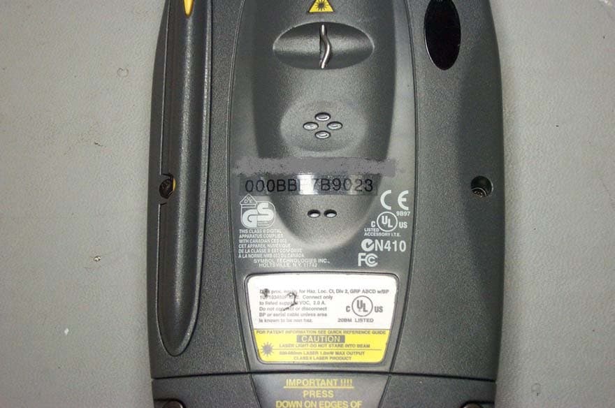
PB2SPT1800
Oct 08, 2003WAV ChameleonRF hand held terminal
Equipment Class
DSS - Part 15 Spread Spectrum Transmitter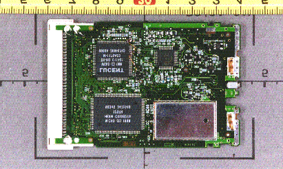
PB2WO80A
Mar 13, 2001Chameleon WLAN 80 Wireless LAN Adapter
Equipment Class
DSS - Part 15 Spread Spectrum Transmitter