PB4DGSCN100Data Guard RF Scan Station
Imation Corp.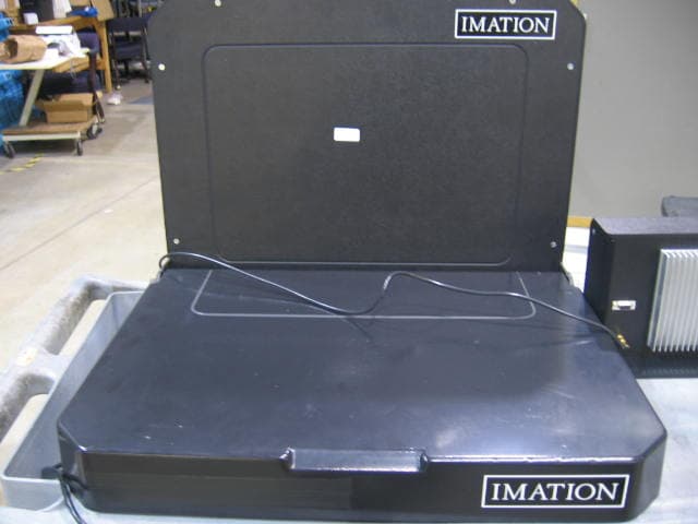
Click to zoom
Application Details
- Equipment Class
- DXX - Part 15 Low Power Communication Device Transmitter
- Date of Grant
- Mar 07, 2007
- Application Purpose
- Original Equipment
- Date of Application
- Mar 07, 2007
- Equipment Note
- Data Guard RF Scan Station
- Frequency Range
- 13.55300000 - 13.56700000
- Company
- Imation Corp.
- Country
- United States
Documents & Files
Document Text
Text extracted from the exhibit documents filed with the FCC. Open a document above to read the original.
Users Manual
Introduction The Imation DataGuard rf™ Scan Station uses the latest RFID technology to track the movement of cartridges in and out of a data center, off-site facility, or DR location. The Scan Station reads RFID-enabled cartridges, either individually or within a transport case, as they arrive and exit a location. The DataGuard rf™ Tape Tracking System automatically logs each cartridge transaction into a tracking database that is linked to the customer’s tape management system. This solution efficiently accounts for the location of all data cartridges and provides both reporting and audit capabilities. DataGuard rf Scan Station Contents* 1. DataGuard rf Scan Station (Model #DGSCN-100) 2. DataGuard rf RFID Antenna Pad (Model #DGANT-100) Safety Instructions—please read thoroughly before using the Scan Station! Always follow the basic precautions listed below to avoid the possibility of serious injury or even death from electrical shock, short-circuiting, damages, fire or other hazards. These precautions include, but are not limited to, the following: Keep a copy of the operating manual close to the Scan Station for easy reference for all operators. Follow the Operator’s Manual carefully. Follow the correct procedure when setting up the device. The Scan Station reader model DGSCN-100 and Antenna Pad model DGANT-100 are designed to work together. Neither should be used with other unauthorized equipment. 1 3. RS-232 Cable** (Part #XX-XXXX-XXXX-X) 4. Power Cable Preliminary Copy **This RS-232 Cable must be used to minimize risk of harmful interference. *Specifications are subject to change without notice. Do not open this device or attempt to disassemble or modify it. The device contains no user-serviceable parts. If it appears to be malfunctioning, have it inspected by qualified service personnel. Modifying or disassembling the product will void the warranty on this product. Do not expose this device to rain, use it near water or in damp or wet conditions, or place containers on it that contain liquids that might spill into an opening. If unusual smells, sounds, or smoke emanate from the Scan Station or if liquids enter the Scan Station, switch its power off immediately and unplug it from the power outlet. Make sure the host computer and the Scan Station are properly electrically grounded. This device should be used in compliance with all national legal requirements and local electrical codes. The electrical socket outlet should be close to this device and easily accessible. Use this device only with the Imation DataGuard rf Tape Tracking System and associated software. Pacemaker warning The Scan Station creates an electromagnetic field below valid limits defined for cardiac pacemakers, but there should be a minimum distance of 25 cm (10 inches) between the antenna pad and a cardiac pacemaker. People with cardiac pacemakers should not remain close to the antenna pad for any lengthy amount of time. Service warning for qualified service personnel— Caution o Disconnect the power cord before servicing. o The Scan Station uses a double-pole/neutral fuse. o The fact that the LEDs have turned off does not mean that the device is discharged. No part of this publication may be reproduced, transmitted, transcribed, stored in a retrieval system, or translated into any language in any term by any means without the written permission of Imation Corporation. Imation reserves the right to make any changes or improvements in the products described in this document at any time without prior notice. 2 Setting up the DataGuard rf Scan Station and Antenna Pad Follow these steps to set up and properly position the Scan Station reader and antenna pad: • Make sure the host computer is turned off and that no power is supplied to the Scan Station. o The host computer should be using the either Windows® 2000 or XP operating systems. o The host computer should have the RFID tracking software for the DataGuard rf Tape Tracking System installed (see Section 3 of the manual for the DataGuard rf Tape Tracking System). • Set up the antenna pad away from large pieces of metal that may interfere with the operation of the antenna. o No power should be applied to the Scan Station reader until after the antenna pad is attached. o The Scan Station reader must be at least 15 cm (6 inches) away from the antenna pad. Leave sufficient space around the Scan Station reader and antenna pad to allow proper air circulation to avoid overheating. Position the Scan Station reader so that the operator can observe the activity LEDs (see below) during scanning or initialization of the tags. o The antenna pad must be at least 50cm (20 inches) away from large pieces of metal. Large pieces of metal include— Table legs, edges, and drawers Metal cabinets, cases, and equipment Metal studs in walls Small pieces of metal may also affect the antenna depending on their size and orientation. Keep coiled cable or wire away from the antenna. If there is a second Scan Station near by, its antenna must be at least XX cm (XX feet) from this Scan Station or any other 13.56 MHz HF RFID antenna. • Connect the antenna pad cable to the scanner body. See Figure 1 below. o Arrange the antenna pad cable away from the antenna. Figure1 • Attach RS-232 cable from the Scan Station reader to the suitable RS-232/COM port on the host computer. o Arrange the RS-232 cable away from the antenna pad. o Note—the operating system on the host computer will only allocate the COM port once on start-up. Do not user other software on the COM port because it might interfere with the operation of the Scan Station. 3 o Use only the supplied RS-232 cable to maintain minimum radio interference. • Plug the power cable from the Scan Station reader into a suitable (100-240VAC; 50- 60Hz) electrical power outlet. o Arrange the power cable away from the antenna pad. • Turn on the host computer to allow it to recognize the Scan Station. Using the DataGuard rf …
Text truncated - open the document above for the full version.
Cover Letter(s)
Request for Confidentiality FCC ID No:PB4DGSCN100 To: Federal Communications Commission 7435 Oakland Mills Road Columbia, MD 21046-1609 Intertek, Inc. 7250 Hudson Blvd., Suite 100 Oakdale, MN 55728 February 13, 2007 Feig Electronic requests, pursuant to 47CFR 0.459, post grant confidentiality for portions of the material contained in this application such that the identified material will be withheld from public inspection following the grand of this authorization. This material, as indicated by request for confidentiality of the item during the electronic submission process and further identified below, includes: 1. Electrical Schematics, Adobe Acrobat file ́ ID ISCLRM2000 - Schematic Analog PCB.pdf ́ (12 pages) ID ISCLRM2000 - Schematic Digital PCB.pdf (13 pages) 2. Block Diagram, Adobe Acrobat file ́ ID ISCLRM2000 - Block Diagram.pdf ́ (1 page) Specifically, these exhibits contain information relating to the circuit function and complexity that could be benefit to competitors. The material contains trade secrets and confidential information that Feig Electronic does not customarily release to the public and which is otherwise not generally available to the public. Please contact me by phone at +49 6471-3109-421, by fax at +49 6471-3109-99, by email at [email protected], or by correspondence at the address below if there is any further question or additional information needed concerning this filing. Sincerely, Horst Großer Feig Electronic GmbH Lange Str. 4 35781 Weilburg Germany
ID Label/Location Info
6” x 1.75” Assembled in U.S. of non-U.S. and U.S. components Imation Enterprises Corp. Oakdale, MN 55128 U.S.A. FCC ID: PB4DGSCN100 IC: 6900A-DGSCN100 TM Scan Station This device complies with part 15 of the FCC rules. Operation is subject to the following two conditions: This device may not cause harmful interference, and this device must accept any interference received, including interference that may cause undesired operation. © Imation 2007 52000348905-A area for serial no. label Model# DGSCN-100 Conforms to UL Std 60950-1 Cert. to CAN/CSA Std C22. 2 No. 60950-1 100-240V 0.4A 40W 50-60Hz XXXXXX Listed
Test Report
TEST REPORT Report Number: 3113388MIN-001 Project Number: 3113388 January 9, 2007 Evaluation of the Scan Station with RFID Antenna Pad FCC ID: PB4DGSCN100 to FCC Part 2 FCC Part 15, Subpart C, Section 15.225 For Imation Test Performed by: Test Authorized by: Intertek 7250 Hudson Blvd. Suite 100 Oakdale, MN 55128 Imation 1 Imation Place 304-2A-30 Oakdale, MN 55128 Prepared by: Date:January 9, 2007 Uri Spector Reviewed by: Date:January 9, 2007 Norman Shpilsher FCC ID: PB4DGSCN100 Page 2 of 19 CONTENTS 1.0 GENERAL DESCRIPTION...........................................................................................................3 1.1 Related Submittals Grants................................................................................................................3 1.2 Product Description.........................................................................................................................3 1.4 Test Facility.....................................................................................................................................3 2.0 SYSTEM TEST CONFIGURATION.............................................................................................4 2.1 Justification......................................................................................................................................4 2.2 EUT Setup........................................................................................................................................4 2.3 EUT Exercising Software................................................................................................................4 2.4 Special Accessories..........................................................................................................................4 2.5 Equipment Modification..................................................................................................................4 2.6 Support Equipment List and Description.........................................................................................4 2.7 Test Configuration Block Diagrams ................................................................................................ 5 3.0 TEST RESULTS.............................................................................................................................6 3.1 Field Strength of Radiated Emissions, FCC 15.225(a)(b)(c), 15.209..............................................7 3.2 Out of Band Spurious Emissions, FCC 15.225(d), 15.209..............................................................8 3.3 Field Strength of Spurious Emissions, FCC 15.205, 15.209...........................................................9 3.5 Bandwidth of Emissions, FCC 15.215...........................................................................................11 3.6 Line Conducted Emissions, FCC 15.207.......................................................................................14 3.6 Test Procedure...............................................................................................................................16 3.7 Field Strength Calculation.............................................................................................................17 3.8 Measurement Uncertainty..............................................................................................................17 4.0 TEST EQUIPMENT.....................................................................................................................18 FCC ID: PB4DGSCN100 Page 3 of 19 1.0 GENERAL DESCRIPTION 1.1 Related Submittals Grants This is single application of the Scan Station (model: DGSCN-100 s/n: 003) with RFID Antenna Pad (model DGANT-100 s/n: 002) for Certification under Part 15 Subpart C. There are no other simultaneous applications . 1.2 Product Description The Scan Station with RFID Antenna Pad is operating at 13.56 MHz. The RF ID Transmitter is incorporated in the Scan Station with RFID Antenna Pad. The intended use of the System is to generate and transmit a RF signal from the Antenna to the RF ID Tag; the same antenna is used to receive RF signal from the tag. The Scan Station with RFID Antenna Pad is powered at 120 VAC, 60 Hz. The RFID Scan Station transmitter is connected to the RFID Antenna pad via 90cm Antenna Cable with SMA connector. Sample Submitted: January 8, 2007 Test Work Started: January 8, 2007 Test Work Completed: January 9, 2007 Emission measurements were performed according to the procedures in ANSI C63.4-2003. All field strength radiated emissions measurements were performed in the semi-anechoic chamber, and for each scan, the procedure for maximizing emissions in Appendices D and E were followed. All field strength radiated tests were performed at an antenna to EUT distance of 3 meters, unless stated otherwise in the "Justification Section" of this Application. 1.4 Test Facility The test site facility used to collect the radiated and conducted measurement data is located at 7250 Hudson Blvd., Suite 100, Oakdale, Minnesota. This test facility has been fully described in a report dated on December 2005 submitted to FCC. Please reference the site registration number: 90706, dated December 6, 2005. FCC ID: PB4DGSCN100 Page 4 of 19 2.0 SYSTEM TEST CONFIGURATION 2.1 Justification To demonstrate the Scan Station with RFID Antenna Pad compliance the system was tested with 90cm antenna cable and RS232 communication cable, the Field Strength of Fundamental frequency and Out of Band Spurious Emissions were tested for 90cm antenna cable and RS232 (with Ferrite) cable. The Conducted Emissions test was performed with terminated antenna output. 2.2 EUT Setup For simplicity of testing, the transmitter was set to transmit continuously under the exercising software. 2.3 EUT Exercising Software ISOStart, ID ISC.LR200 test software. 2.4 Special Accessories There are no special accessories necessary for compliance of these products. 2.5 Equipment Modif…
Text truncated - open the document above for the full version.
Test Setup Photos
Radiated Emissions Test Configuration Radiated Emissions Test Configuration Radiated Emissions Test Configuration Radiated Emissions Test Configuration Line Conducted Emissions Test Configuration Line Conducted Emissions Test Configuration
Contact Information
Applicant
Lawrence Lai(Project Management Manager)
Technical Contact
Imation CorporationStephen Rothermel
[email protected]651-704-3497
1 Imation Place · Oakdale · United States
Non-Technical Contact
Imation CorporationGreg Wiesjahn
[email protected]651-704-6188
Test Firm
Intertek Testing ServicesUri Spector
Technical Specifications
| # | Rule Parts | Frequency Range | Power Output |
|---|---|---|---|
| 1 | 15C | 13.553 MHz - 13.567 MHz | - |
Other Applications from Imation Corp.

PB4-TDKA08
May 10, 2015Wireless Speaker
Equipment Class
DSS - Part 15 Spread Spectrum Transmitter
PB4-TDKWR680
Dec 16, 2014Wireless Headphones
Equipment Class
DXX - Part 15 Low Power Communication Device Transmitter
PB4-TDKA28
Nov 20, 2014Wireless Speaker
Equipment Class
DSS - Part 15 Spread Spectrum Transmitter
PB4-TDKA20
Jul 13, 2014Wireless Speaker
Equipment Class
DSS - Part 15 Spread Spectrum Transmitter
PB4-TDKWR780
May 29, 2014Wireless Headphones
Equipment Class
DXX - Part 15 Low Power Communication Device Transmitter