PB6-02011WLAN PCMCIA Card
Tellus Group Corp.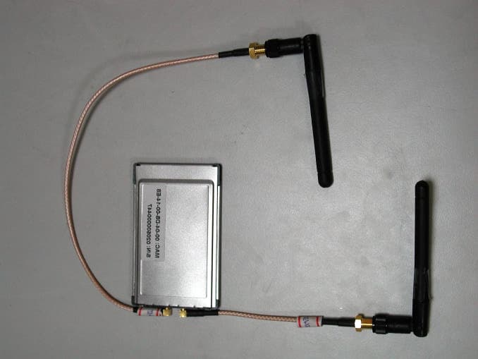
Click to zoom
Application Details
- Equipment Class
- DTS - Digital Transmission System
- Date of Grant
- Oct 27, 2002
- Application Purpose
- Original Equipment
- Date of Application
- Oct 27, 2002
- Equipment Note
- WLAN PCMCIA Card
- Frequency Range
- 2412.00000000 - 2462.00000000
- Company
- Tellus Group Corp.
- Country
- Taiwan
Documents & Files
Document Text
Text extracted from the exhibit documents filed with the FCC. Open a document above to read the original.
Users Manual
This device is intended only for OEM integrators under the following conditions, the OEM integrators should have all the followings met for the continuing in compliance with the FCC rules: Modular Authorization Condition 1) The antenna must be installed such that 20 cm is maintained between the antenna and users, and 2) The transmitter module may not be co-located with any other transmitter or antenna. As long as the 2 conditions above are met, further transmitter testing will not be required. However, the OEM integrator is still responsible for testing their end-product for any additional compliance requirements required with this module installed (for example, digital device emissions, PC peripheral requirements, etc.). IMPORTANT NOTE: In the event that these conditions can not be met (for example certain laptop configurations or co-location with another transmitter), then the FCC authorization is no longer considered valid and the FCC ID can not be used on the final product. In these circumstances, the OEM integrator will be responsible for re-evaluating the end product (including the transmitter) and obtaining a separate FCC authorization. End Product Labeling This transmitter module is authorized only for use in devices where the antenna may be installed such that 20 cm may be maintained between the antenna and users (for example access points, routers, wireless ASDL modems, and similar equipment). The final end product must be labeled in a visible area with the following: "Contains TX FCC ID: PB6-02011". Manual Information That Must be Included The users manual for end users must include the following information in a prominent location. "IMPORTANT NOTE: To comply with FCC RF exposure compliance requirements, the antenna used for this transmitter must be installed to provide a separation distance of at least 20 cm from all persons and must not be co-located or operating in conjunction with any other antenna or transmitter."
Users Manual
Wireless LAN PC Card User's Manual Version 1.7 2002-08-20 1 Copyright © 2002 by manufacturer. All rights reserved. ü No part of this documentation may be reproduced in any form or by any means or used to make any derivative work (such as translation, transformation, or adaptation) without written permission from the copyright owner. ü All the other trademarks and registered trademarks are the property of their respective owners. Statement of Conditions ü The content described in this manual may be improved or changed at any time and it is subject to be changed without notice. ü Manufacturer assumes no responsibility for errors contained herein or for direct, indirect, special, incidental or consequential damages with the furnishing, performance, or use of this manual or equipment supplied with it, even if manufacturer of its suppliers have been advised of the possibility of such damages. Electronic Emission Notices ü This device complies with Part 15 of the FCC Rules and Canada RSS-210. Operation is subject to the following two conditions: 1. This device may not cause harmful interference. 2. This device will accept any interference received, including interference that may cause undesired operation. FCC Radio Frequency Interference Statement ü This equipment has been tested and found to comply with the limits for a class B digital device, pursuant to Part 15 of the FCC rules. These limits are designed to provide reasonable protection against harmful interference when the equipment is operated in a commercial environment. This equipment generates, uses, and can radiate radio frequency energy and, if not installed and used in accordance with the instruction manual, may cause harmful interference to radio communications. Operation of this equipment in a residential area is likely to cause harmful interference in which case the user need to correct the interference at his area. If the equipment causes interference to radio or television reception, try to correct the interference by using one or more of the following measures: ü Plug the equipment into an outlet that is on a different circuit from the television or radio. ü Change the direction of the television or radio antenna until the interference disappears. ü Move the equipment to one side or the other of the television or radio. ü Move the equipment farther away from the television or radio. ü To assure continued compliance, any changes or modifications not expressly approved by manufacturer could void the user’s authority to operate the equipment. FCC Radiation Exposure Statement ü This device and its antennas must operate with a separation distance of at least 20 cm from all persons and must not be co-located or operating in conjunction with any other antenna or transmitter. End users must be provided with specific operating instructions for satisfying RF exposure compliance. ü ü This product has been certified in Canada, France, Germany, Italy, Spain, Sweden, Taiwan, UK, and US. LIMITED WARRANTY ü This product is warranted by manufacturer to be free from defects in material and workmanship for one (1) year from the date of purchase. ü During this period if this product is found to be defective in material or workmanship, manufacturer or one of its authorized service facilities will at its option either repair or replace this product without charge, subject to the following conditions, limitations and exclusions: 1. This warranty extends to the original consumer purchaser only and is not assignable or transferable. 2 2. This warranty shall not apply to any product which has been subjected to misuse, abuse, abnormal use, negligence, alteration or accident, or has had its serial number altered or removed. 3. This warranty does not apply to any defects or damage directly or indirectly caused by or resulting from the use of unauthorized replacement parts and/or service performed by unauthorized personnel. 4. This warranty does not apply to the software driver that accompanies this product. ü This warranty is made expressly in lieu of all other warranties, expressed or implied, including but not limited to any implied warranty of merchantability of fitness for a particular purpose, and all other obligations on the part of Manufacturer provided, however, that if the disclaimer of implied warranties is ineffective under applicable law, the duration of any implied warranties arising by operation of law shall be limited to one (1) year from the date of purchase or such longer period as may be required by applicable law. ü Manufacturer hereby disclaims any and all liabilities for consequential and incidental damages arising out of or in connection with any breach of this warranty or any other claim with respect to this product, including but not limited to claims of negligence, strict liability in tort or breach of contract. 3 Table of Contents 1 INTRODUCTION.......................................................................................................................5 1.1 Features...................................................................................................................................................................................5 1.2 Applications.............................................................................................................................................................................5 1.3 Wireless LAN System..........................................................................................................................................................5 1.3.1 Peer-to-Peer Configuration....................................................................................................................................................5 1.3.2 Access Point Configuration...................................................................................................................................................6 2 INSTALLATION............................................…
Text truncated - open the document above for the full version.
Cover Letter(s)
Training Research Co., Ltd. 255 Nan-yang Street, Shijr, Taipei Hsien 221, Taiwan, R.O.C. TEL: 886-2-26935155 FAX: 886-2-26934440 TRCSince1985 ® August 23, 2002 RE : TeLLUS Group Corp. FCC ID : PB6-02011 Dear Timothy: Regarding to your comment, we have made some remarks upon your advice; the modifications are summarized as follows: 1. The label with higher resolution is attached with the correct FCC ID. Please find it in the attachment 2. The label is updated in order to comply the 15.19 requirement, attached as exhibit is uploaded. 3. The manual is also made the modification upon your requests. 4. The EUT is applied in the Modular approval and all the necessary changes upon such approval is added in the manual. Also, regarding to the issue about the MPE statement is all have been changed form 5cm to 20cm. Please find them all in the attachment. 5. Please find the attached hardcopy of our band-edge testing software for the illustration of compliance. The matters needed with the modified report are attached with this reply. Should you have any questions, please feel free to contact us. Thanks for your kindly consideration. Sincerely yours, Eric Wong Testing Engineer Training Research Co Ltd.
Cover Letter(s)
Training Research Co., Ltd. 255 Nanyang Street, Shijr, Taipei Hsien 221, Taiwan, R.O.C. TEL: 886-2-26935155 FAX: 886-2-26934440 Email: [email protected] TRCSince1985 ® September 28, 2002 RE: TeLLUS Group Corp. FCC ID: PB6-02011 Dear Timothy: After the review of your comments, we have made some response upon your advice; they are summarized as follows: 1. The label with the corrected DoC notification is uploaded. 2. The missed portion of the data sheet of the ISL3873B is uploaded. 3. The Compliance sheet should be shown in the manual for the DoC device is uploaded. 4. By the manufacturer claims, the product shall not only be supplied to the system integrators but also for the ordinary end-user also. It should be s a little bit strange if the info you mentioned have been printed in the manual from the ordinary end-user view. So we haven’t added for the benefits of the end-user. 5. For the band-edge issue, please discard the part attached at the first-time, and only refer to the one we have uploaded last time. The difference found maybe made by the mistakes we took at the first-time. The materials uploads last-time is re-do and shown only the data of the EUT itself, done with my witness. Should you have any questions or more information is needed, please don’t hesitate to ask us. Thank you. Sincerely yours, Eric Wong Project Engineer Training Research Co Ltd.
Cover Letter(s)
Training Research Co., Ltd. 255 Nanyang Street, Shijr, Taipei Hsien 221, Taiwan, R.O.C. TEL: 886-2-26935155 FAX: 886-2-26934440 Email: [email protected] TRCSince1985 ® October 23, 2002 RE: TeLLUS Group Corp. FCC ID: PB6-02011 Dear Timothy: After the review of your comments, we have made some response upon your advice; they are summarized as follows: 1. The updated “Request for Confidentiality” is uploaded, added the block diagram be a part to be held in confidential. 2. The manual with the part you mentioned is added and uploaded, the Compliance sheet should be shown in the manual for the DoC device is also added and uploaded. 3. The TeLLUS wants to designate the uses of the device to be only for the MODULE use, TeLLUS have followed you comments about adding the special instruction for the OEM integrator in the manual as the modular approval applied. Please find the materials uploaded. 4. The RBW & VBW of the testes are 100kHz. Should you have any questions or more information is needed, please don’t hesitate to ask us. Thank you. Sincerely yours, Eric Wong Project Engineer Training Research Co Ltd.
Cover Letter(s)
American Telecommunications Certification Body Inc. 6731 Whittier Ave, McLean, VA 22101 July 26, 2002 RE: TeLLUS Group Corp. FCC ID: PB6-02011 After a review of the submitted information, I have a few comments on the above referenced Application. 1) Please provide a higher resolution sample label. The one provided is not easily readable. 2) This device is considered both a Part 15 transmitter and a Class B PC Peripheral and is subject to the labeling and users manual requirements for both. The DOC labeling on the device should usually include the phrases "Tested to Comply With FCC Standards" and "FOR HOME OR OFFICE USE" as specified by 15.19. Please update the label to include this. 3) The users manual appears to be missing the information required by 15.21, 15.105, & 2.1077. 4) PCMCIA Cards with integrated antennas (built in) are expected to normally claim 2.5 cm for MPE compliance. The antennas for this product are not built in, but based on their short coax length it is uncertain how this device is to be used. Please explain the intended use for this product. How will the antennas be used and what is the expected distance from users. (Please note that the users manual states 5 cm, while the operational description states 15 cm). For example, if this device is intended only for integrators into devices like access points, then 20 cm may be assumed. However, if this is intended for integrators, then a modular approval must be requested and a cover letter covering the modular requirements must be submitted. 5) The EUT ad a maximum transmit power of 104.39 dBuV/m for the low channel and 108.6 dBuV/m for the high channel. From the bandedge plots provided, the following is obtained ChannelReadingDelta from Bandege Low109.1-49.89=59.2 High108.6-47.22=61.4 which shows compliance with the 74 dBuV/m peak limit. However please provide additional information to show compliance the average 54 dBuV/m limit. Timothy R. Johnson Examining Engineer mailto: [email protected] The items indicated above must be submitted before processing can continue on the above referenced application. Failure to provide the requested information may result in application termination. Correspondence should be considered part of the permanent submission and may be viewed from the Internet after a Grant of Equipment Authorization is issued. Please do not respond to this correspondence using the email reply button. In order for your response to be processed expeditiously, you must submit your documents through the AmericanTCB.com website. Also, please note that partial responses increase processing time and should not be submitted. Any questions about the content of this correspondence should be directed to the sender.
Cover Letter(s)
American Telecommunications Certification Body Inc. 6731 Whittier Ave, McLean, VA 22101 August 28, 2002 RE: TeLLUS Group Corp. FCC ID: PB6-02011 After a review of the submitted information, I have a few comments on the above referenced Application. 1) The updated DoC labeling is missing the 's' on Standards. The phrase should be "Tested to Comply With FCC Standards". Please update the label to include this. 2) The modular request letter references 13 pages of data sheets for the "ISL3873B". This was not provided. Please provide this. 3) For the users manual to be in compliance with 2.1077, the following information must be on the same page as the FCC Statements: (a) Identification of the product, i.e. name and model number. (b) The identification, by name, address and telephone number, of the responsible party. The responsible party is defined as either the manufacturer, or if the equipment is imported, the importer. The responsible party for a Declaration of Conformity must be located within the United States. 4) Item 7 in the modular letter references specific information that does not appear to be in the users manual. However, for this approval we would recommend more information be added to the manual for completeness. Additionally, the users manual references installing the card in a computer, but this device is only supposed to be for integrators (as given in our previous discussions) where certain conditions can be maintained. Please correct the manual to include the information given in the additional attachment. 5) The new bandedge plots provided (RBW/VBW unknown) to show compliance with the 54 dBuV/m appear about 8 dB below the plots given in the original report in section 7.5 (RBW = 100 kHz, VBW = 100 kHz). Please explain: (a) why there is this difference (b) provide the RBW & VBW of the new measurements (c) explain if this measurement was radiated or conducted. It should have been radiated. Timothy R. Johnson Examining Engineer mailto: [email protected] The items indicated above must be submitted before processing can continue on the above referenced application. Failure to provide the requested information may result in application termination. Correspondence should be considered part of the permanent submission and may be viewed from the Internet after a Grant of Equipment Authorization is issued. Please do not respond to this correspondence using the email reply button. In order for your response to be processed expeditiously, you must submit your documents through the AmericanTCB.com website. Also, please note that partial responses increase processing time and should not be submitted. Any questions about the content of this correspondence should be directed to the sender.
Cover Letter(s)
American Telecommunications Certification Body Inc. 6731 Whittier Ave, McLean, VA 22101 September 30, 2002 RE: TeLLUS Group Corp. FCC ID: PB6-02011 After a review of the submitted information, I have a few comments on the above referenced Application. 1) Please comment of if the uploaded information for ISL3873B is to be considered confidential. If so, please update the confidentiality letter. 2) The information uploaded for 2.1077 should include all of the following: (1) Identification of the product, i.e. name and model number. (2) A statement similar to that contained in Section 15.19(a)(3) that the product complies with Part 15 of the regulations. (3) The identification, by name, address and telephone number, of the responsible party. The responsible party is defined as either the manufacturer, or if the equipment is imported, the importer. The responsible party for a Declaration of Conformity must be located within the United States. Your compliance statement provided included items 1 & 3. However, please correct by adding item 2. 3) One of your recent responses provided a modular approval letter for integrators. After providing this letter, we were assuming at this point that the device was only for integrators. However your latest response stated that this device is both for the end user and integrators. Now this application appears to be addressing 2 different RF exposure configurations as shown below. Due to the RF exposure conditions and modular nature for one configuration this device would require to be certified separately under 2 different FCC ID Numbers (one for integrators, the other for end users). Please note that the product would have to be labeled differently for each configuration (the product should not contain 2 FCC ID's at the same time). For instance, the device would be labeled with a single FCC ID for integrators. The label for end users would be different and contain the other FCC ID. a) Integrators, 20 cm distance classified as mobile, modular approval so the device may be installed internal to certain products by an integrator, specific manual information should address modular concerns. b) End users, this RF exposure configuration is still unclear, but previous information suggested 5 (original users manual) or 15 cm (operational description) which would be portable. Due to RF exposure concerns, the FCC does not allow modular approvals for mobile classifications or configurations. It must be clear how this device will meet its RF exposure requirements for the end user configuration(s), both throughout the application and in the users manual. In this application, it is uncertain how RF exposure issues will be applied for end users. The antennas for this product are not built in, but based on their short coax length it is uncertain how an end user will use this device and how the antennas will be mounted since the users manual does not provide any of this information, nor have any "mounting brackets" or holders appear to be part of the product. Please justify the intended use for this product and how the antennas will be used and what is the expected distance from users. Please let us know how to proceed evaluating this device given its 2 "classifications". 4) Please provide the RBW & VBW of the newest bandedge measurements provided and confirm if this was a radiated measurement. z Page 2September 30, 2002 Timothy R. Johnson Examining Engineer mailto: [email protected] The items indicated above must be submitted before processing can continue on the above referenced application. Failure to provide the requested information may result in application termination. Correspondence should be considered part of the permanent submission and may be viewed from the Internet after a Grant of Equipment Authorization is issued. Please do not respond to this correspondence using the email reply button. In order for your response to be processed expeditiously, you must submit your documents through the AmericanTCB.com website. Also, please note that partial responses increase processing time and should not be submitted. Any questions about the content of this correspondence should be directed to the sender.
Operational Description
Document Type TGC PROPRIETARY Rev. 0.1 RD-Tho02-001 7/12/2002 RD-VAN02-001_0207 - Operation Description of C125S 1/1 02/07/12 03:13 PM Operational Description The C125S is designed to meet the mobility, performance, security, interoperability, management, reliability requirements of IEEE 802.11b high data rate standard. When installed, C125S can communicate with other IEEE 802.11b compatible products to create a wireless network in your office or home.C125S can be powered with 3.3 or 5VDC. And two dipole antennas used to tranceive RF signal. This equipment should be installed and operated with the minimum 15 cm between your body and the Antenna. The other instruction, please have a look at the users manual.
RF Exposure Info
Training Research Co., Ltd. 255 Nanyang Street, Shijr, Taipei Hsien 221, Taiwan, R.O.C. TEL: 886-2-26935155 FAX: 886-2-26934440 TRCSince1985 ® Measurement of MPE 1. Foreword In adopt with the Human Exposure IEEE C95.1, and according to the FCC 1.1310. The Maximum Permissible Exposure (MPE) is obligated to measure in order to prove the safety of radiation harmfulness to the human body. The Gain of the antenna used is measured in an Anechoic chamber. The maximum total power to the antenna is to be recorded. By adopting the Friis Transmission Formula and the power gain of the antenna, we can find the distance right away from the product, where the limit of the MPE is. 2. Description of EUT EUT : Wireless LAN PC Card Classification : Mobile Device (i) Under normal use condition, the antenna is at least 20cm away from the user; (ii) Warning statement for keeping 20cm separation distance and the prohibition of operating next to the person has been printed in the user’s manual Model No. : C125S Granted FCC ID : PB6-02011 Frequency Range : 2.412 GHz ~ 2.462GHz Antenna Kit : 2 sets of 2 external dipole antennas are tested separately (Ant. A: ACON Advance Connector Inc.; and Ant. B: Antenniques Co., Ltd.) Supported Channel: 11 Channel Modulation Skill : DBPSK, DQPSK, CCK Power Type : Powered by the PCMCIA slot of the client device Applicant : TeLLUS Group Corp. 4/F, No.15, Industry E. Rd. IX, Science-based Industrial Park, Hsinchu 300, Taiwan, R.O.C. Training Research Co., Ltd. 255 Nanyang Street, Shijr, Taipei Hsien 221, Taiwan, R.O.C. TEL: 886-2-26935155 FAX: 886-2-26934440 TRCSince1985 ® 3a. Limits for Maximum Permissible Exposure (MPE) (Antenna A) Frequency Range (MHz) Electric Field Strength (V/m) Magnetic Filed Strength (H) (A/m) Power Density (S) (mW/cm2) Averaging Time |E| 2 , |H| 2 or S (minutes) (A) Limits for Occupational/Controlled Exposure 0.3-3.0 614 1.63 100 6 3.0-30 1842/f 4.89/f 900/f 2 6 30-300 61.4 0.163 1.0 6 300-1500 -- -- f/300 6 1500-100,000 -- -- 5 6 (B) Limits for General Population/Uncontrolled Exposure 0.3-1.34 614 1.63 100 30 1.34-30 824/f 2.19/f 180/f 2 30 30-300 27.5 0.073 0.2 30 300-1500 -- -- f/1500 30 1500-100,000 -- -- 1.0 30 [The EUT is tested in transmit and receive modes and in the first, middle and the last channel separately. The following shows only our observation have the greatest emissions.] According to OET BULLETIN 56 Fourth Edition/August 1999, Equation for Predicting RF Fields: Friis Transmission Formula: 23 22 /10075.9 )20(4 439.170.31 4 cmmW R PG S − ×= × == ππ Where: S = power density (in appropriate units, e.g. mW/cm2) P = power input to the antenna (in appropriate units, e.g., mW) G = power gain of the antenna in the direction of interest relative to an isotropic radiator R = distance to the center of radiation of the antenna (appropriate units, e.g., cm) The Numeric gain G of antenna with a gain specified in dB is determined by: G = Log -1 (dB antenna gain/10) G = Log -1 (1.58 / 10) = 1.439 Training Research Co., Ltd. 255 Nanyang Street, Shijr, Taipei Hsien 221, Taiwan, R.O.C. TEL: 886-2-26935155 FAX: 886-2-26934440 TRCSince1985 ® 3b. Limits for Maximum Permissible Exposure (MPE) (Antenna B) Frequency Range (MHz) Electric Field Strength (V/m) Magnetic Filed Strength (H) (A/m) Power Density (S) (mW/cm2) Averaging Time |E| 2 , |H| 2 or S (minutes) (A) Limits for Occupational/Controlled Exposure 0.3-3.0 614 1.63 100 6 3.0-30 1842/f 4.89/f 900/f 2 6 30-300 61.4 0.163 1.0 6 300-1500 -- -- f/300 6 1500-100,000 -- -- 5 6 (B) Limits for General Population/Uncontrolled Exposure 0.3-1.34 614 1.63 100 30 1.34-30 824/f 2.19/f 180/f 2 30 30-300 27.5 0.073 0.2 30 300-1500 -- -- f/1500 30 1500-100,000 -- -- 1.0 30 [The EUT is tested in transmit and receive modes and in the first, middle and the last channel separately. The following shows only our observation have the greatest emissions.] According to OET BULLETIN 56 Fourth Edition/August 1999, Equation for Predicting RF Fields: Friis Transmission Formula: 23 22 /10996.9 )20(4 585.170.31 4 cmmW R PG S − ×= × == ππ Where: S = power density (in appropriate units, e.g. mW/cm2) P = power input to the antenna (in appropriate units, e.g., mW) G = power gain of the antenna in the direction of interest relative to an isotropic radiator R = distance to the center of radiation of the antenna (appropriate units, e.g., cm) The Numeric gain G of antenna with a gain specified in dB is determined by: G = Log -1 (dB antenna gain/10) G = Log -1 (2.00 / 10) = 1.585
Test Report
Test Report -------------------------------------------------------------------------------- 44/52 Report No.: T6915431 Training Research Co., Ltd., TEL: 886-2-26935155, Fax: 886-2-26934440 7.5 Test Result of Bandedge If any 100 kHz bandwidth outside these frequency bands, the radio frequency power that is produced by the modulation products of the spreading sequence, the information sequence and the carrier frequency shall be either at least 20 dB below that in any 100 kHz bandwidth within the band that contains the highest level of the desired power or shall not exceed the general levels specified id 15.209(a), We perform this section by the conducted manner, the RBW is set to 100kHz and VBW>RBW. We’d made the observation up to 10 th harmonics and the criterion is all the harmonic/spurious emissions must be 20dB below the highest emission level measured. If the emissions fall in the restricted bands stated in the Part15.205(a) must also comply with the radiated emission limits specified in Part15.209(a). The following pages show our observations referring to the channel 1 and 11 respectively. Test Condition & Setup: same as 3.1 Test Report -------------------------------------------------------------------------------- 45/52 Report No.: T6915431 Training Research Co., Ltd., TEL: 886-2-26935155, Fax: 886-2-26934440 Channel 1 This is the hard copy of our bandedge measurement generated by our bandedge testing program. The picture shown above is the bandedge of channel 1. 1. The lobe right by the fundamental side is already 20dB below the highest emission level. 2. The emissions recorded in the restricted band (<2400MHz) is do comply with the Part 15.209(a) – under the limited line marked in red color. Test Report -------------------------------------------------------------------------------- 46/52 Report No.: T6915431 Training Research Co., Ltd., TEL: 886-2-26935155, Fax: 886-2-26934440 Channel 11 This is the hard copy of our bandedge measurement generated by our bandedge testing program. The picture shown above is the bandedge of channel 11. 1. The lobe right by the fundamental side is already 20dB below the highest emission level. 2. The emissions recorded in the restricted band (>2483.5MHz) is do comply with the Part 15.209(a) – under the limited line marked in red color.
Test Report
Test Report -------------------------------------------------------------------------------- 3/52 Report No.: T6915431 Training Research Co., Ltd., TEL: 886-2-26935155, Fax: 886-2-26934440 Tables of Contents I. GENERAL ......................................................................................................................... 5 1.1 Introduction .................................................................................................................. 5 1.2 Description of EUT ....................................................................................................... 5 1.3 Description of Support Equipment ................................................................................. 6 1.4 Configuration of System Under Test .............................................................................. 8 1.5 Verify the Frequency and Channel ................................................................................. 9 1.6 Test Procedure ............................................................................................................ 10 1.7…
Text truncated - open the document above for the full version.
Contact Information
Applicant
John Huang(R&D VP)
Technical Contact
Training Research Co., Ltd.Eric Wong
[email protected]886-2-26935155
255 Nanyang St., Shijr · Taipei Hsien · Taiwan
Non-Technical Contact
Training Research Co., Ltd.Eric Wong
[email protected]886-2-26935155
Test Firm
Training Research Co., Ltd.Jack Tsai
Technical Specifications
| # | Rule Parts | Frequency Range | Power Output |
|---|---|---|---|
| 1 | 15C | 2.41 GHz - 2.46 GHz | 31.00 mW |
Other Applications from Tellus Group Corp.
PB6-06041
Jul 03, 2006WLAN TurboSecure TM AP/Bridge/Repeater
Equipment Class
DTS - Digital Transmission System
PB6-04121
Dec 28, 2005Wireless LAN 11g Access Point
Equipment Class
DTS - Digital Transmission System
PB6-03061
Oct 19, 2005Wireless LAN CF Card
Equipment Class
DTS - Digital Transmission System
PB6-03112
Sep 06, 2005Wireless LAN 11g CardBus Adapter
Equipment Class
DTS - Digital Transmission System
PB6-04021
Aug 22, 2004802.11b CF Card Module
Equipment Class
DTS - Digital Transmission System