PC3GM-151TFT LCD Monitor
GTT Co., Ltd.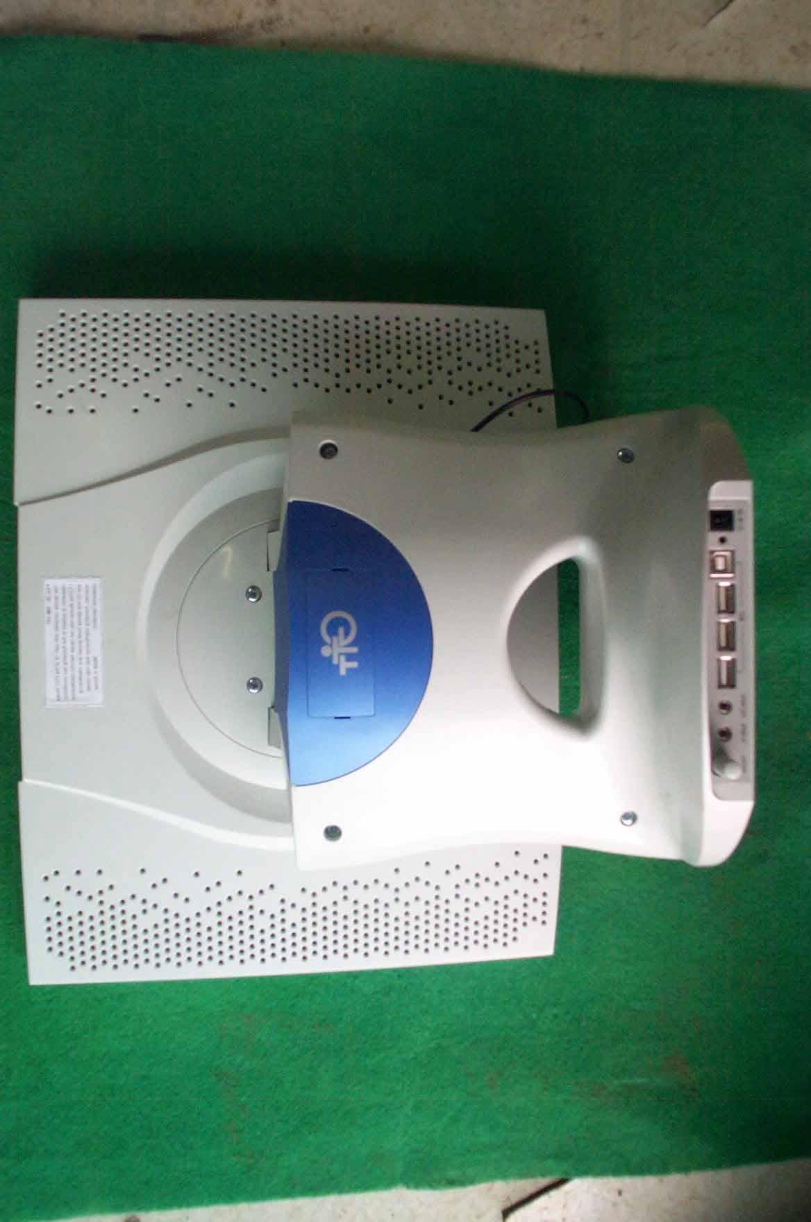
Click to zoom
Application Details
- Equipment Class
- JBP - Part 15 Class B Computing Device Peripheral
- Date of Grant
- Nov 26, 2000
- Application Purpose
- Original Equipment
- Date of Application
- Nov 26, 2000
- Equipment Note
- TFT LCD Monitor
- Company
- GTT Co., Ltd.
- Country
- South Korea
Documents & Files
Document Text
Text extracted from the exhibit documents filed with the FCC. Open a document above to read the original.
Users Manual
GM SeriesUser’s manual PRODUCED BY GTT CO., LTD. GTT CO., LTD. Suite 408, Pungsan Apt. Factory, 1141-2, Baeksuk-dong, Ilsan-gu, Koyang-shi, Kyounggi-do, Korea Tel : 82 31 903 9780, Fax : 82 31 903 9787 E-mail : [email protected] URL : http://www.gtt.co.kr CONTENTS1. Package Contents2. Monitor Parts3. Connecting to PC4. Features5. OSD Menu functions6. Dimension7. Specification8. AV OSD function9. USB function10. Pivot function11. Recommended Use12. Troubleshooting 1 T hank you for your selection of new TFT LCD Monitor. Please take a few minutes to read this User’s manual for the best performance of this monitor.Information in this manual is subject to change without prior notice for improving design, function and etc.IBM, DOS, PC and VGA are trademarks of International Business Machines Corporation. 3 2 Package Contents Your TFT-LCD monitor box should contain the following : Monitor Parts STANDARD PARTS• TFT-LCD monitor • DC Power adapter - Connects to DC IN port on the base of monitor• Power cord - Connects wall outlet to DC Power adapter• D-SUB 15pin video cable - Connects PC to LCD monitor• USB upstream cable - Connects PC to USB ports on the base of monitor• Stereo audio cable - Connects PC sound card to audio input port on the base of monitor • User's manual • Installation CD-ROM OPTIONAL PARTS• Video cables (Composite, S-video) • Audio cable for AV monitor • Pivot software - Must be installed to use the monitor in Portrait mode 9. Audio IN port10. Volume control11. Power input connect12. VGA input connector13. Composite input connector (Optional)14. S-Video input connector (Optional)15. Cable hole 1. Power switch2. Speaker hole3. OSD button4. Power input connector 5. LED indicator6. USB Up stream connector7. USB Down stream connectors8. Audio OUT port 5 4 Connecting to PC To attach your TFT-LCD monitor to your system, follow the instructions hereunder 1. Connect the small DC power cord from the base of the monitor to the head (For first time installation, this step will be completed by the factory) 2. Connect 15-pin D-SUB cable to the connector or display card of your computer system. Tighten all the screws 3. Connect 15-pin D-SUB cable to the appropriate connectors on the back of the monitor head 4. Connect AC adapter cable to the power input connectors on the back of the monitor base 5. Connect one end of the power cord to the AC adapter and the other end to the power outlet 6. Turn on the monitor 7. To complete the setup • Adjustment of the H/V Position and Image Adjust H. Size controls may be required to complete setup of your TFT- LCD monitor. For a full description of these OSD controls, refer to OSD menu functions • Your monitor has two 2 Watt speakers with amplifier. Please connect the speaker jack to the Line out jack of your PC's sound card A. set up your computer system to : 1024 x 768 resolution @ 60Hz. B. Use the following OSD controls - Auto adjust control - Coase or Clock Phase control 6 Features TFT-LCD (Thin film transistor - liquid crystal display) The 13.3/14.1/15.1 inch panel and h ard coating(3H),anti-glare treatment of the front polarizer enables low reflection, anti- static, high-resolution and high-contrast characteristics. Plug-and-Play Compatible This TFT-LCD monitor conforms to the VESA(Video Electronics Standards Association) standard and DDC1/DDC2B. A picture adjustment function makes it possible to adjust the image quality to match the input signal. An automatic size adjustment function is provided. Auto-setup control on OSD screen adjust image position, horizontal size or fine settings Environmentally Friendly The power consumption can be reduced by using this TFT-LCD monitor in combination of a computer that conforms to the VESA DPMS(Display Power Management Signaling) standard.Desk space can be used effectively due to the 20 cm depth. VESA standard wall mounting This TFT-LCD monitor has the VESA (Video Electronics Standards Association) standard wall mounting holes Monitor head can be mounted on the wall using a VESA-compliant wall mount OSD menu functions 7 SEL : Input select button (available in AV monitor) - Allows the user to select the current signal from the following choice : analog RGB input, Composite video input, S-video input MENU : Menu on/move button- Show OSD menu on the screen. Moves the highlighted area down to select one of the functions EXIT : Menu off button - Exit from OSD menu. Exit to main menu from sub menu.UP : Adjust button - Moves the bar left to decrease the adjustment. Start auto adjust. DOWN : Adjust button - Moves the bar right to increase the adjustment. Start auto adjust. OSD (On-Screen-Display) control buttons functions as follows : To access OSD Menu, press MENU button [ MAIN MENU DISPLAY ] 9 8 Controls the brightness of the LCD Use UP or DOWN button to increase or decrease the settin g Controls the contrast of the LCD Use UP or DOWN button to increase or decrease the settingControls the horizontal image position within the display of the LCD Use the UP or DOWN button to move the image right or leftControls the vertical image position within the display of the LCD Use the UP or DOWN button to move the image up or downAutomatically adjust Image Position, Horizontal Size or Fine setting Press UP or DOWN button to adjust the settings automatically • AUTO ADJUST • BRIGHTNESS • CONTRAST • IMAGE HORI. POSITION • MAGE VERT. POSITION Improves focus, clarity and image stabilityUse UP or DOWN button to increase or decrease the setting Improves focus, clarity and image stabilityUse UP or DOWN button to increase or decrease the setting • COASE ( Coarse Tuning) • CLOCK PHASE (Fine Tuning) Press the UP or DOWN button to enter into the following submenu • COLOR Press the MENU button to select the item you wish to change Color temperature Provides two preset color adjustment : 9300K and 6500Select the preset by using MENU button and press EXIT button 11 10 To exits to the OSD main menu, press the EXIT button RGB Adjustment Increases o…
Text truncated - open the document above for the full version.
External Photos
SK TECH CO., LTD. Page 1 of 2 SKT SKTOS-00146 FCC ID : XXXGM-151 External Photographs of EUT SK TECH CO., LTD. Page 2 of 2 SKT SKTOS-00146 FCC ID : XXXGM-151
ID Label/Location Info
SK TECH CO., LTD. Page 1 of 1 SKT SKTOS-00146 FCC ID : XXXGM-151 FCC ID Sample Label & Location Information LABELLING REQUIREMENTS PER ∫∫∫∫ ∫∫∫∫∫∫∫∫ ∫∫∫∫2.928 The Label shown shall be permanently affixed at a conspicuous location on the device and be readily visible to the user at the time of purchase. FCC ID : PC3GM-151 This device complies with part 15 of the FCC Rules. Operation is subject to the following two conditions: (1) This device may not cause harmful interference, and (2) this device must accept any interference received, including interference that may cause undesired operation.
ID Label/Location Info
SK TECH CO., LTD. Page 1 of 1 SKT SKTOS-00146 FCC ID : XXXGM-151 FCC ID Label Sample
Internal Photos
SK TECH CO., LTD. Page 1 of 8 SKT SKTOS-00146 FCC ID : XXXGM-151 Internal Photographs of EUT SK TECH CO., LTD. Page 2 of 8 SKT SKTOS-00146 FCC ID : XXXGM-151 SK TECH CO., LTD. Page 3 of 8 SKT SKTOS-00146 FCC ID : XXXGM-151 SK TECH CO., LTD. Page 4 of 8 SKT SKTOS-00146 FCC ID : XXXGM-151 SK TECH CO., LTD. Page 5 of 8 SKT SKTOS-00146 FCC ID : XXXGM-151 SK TECH CO., LTD. Page 6 of 8 SKT SKTOS-00146 FCC ID : XXXGM-151 SK TECH CO., LTD. Page 7 of 8 SKT SKTOS-00146 FCC ID : XXXGM-151 SK TECH CO., LTD. Page 8 of 8 SKT SKTOS-00146 FCC ID : XXXGM-151
Test Report
SK TECH CO., LTD. Page 1 of 13 SKT SKTOS-00146 FCC ID : XXXGM-151 Certificate of Compliance Test Report No.: SKTOS-00146 NVLAP CODE : 200220-0 Applicant: GTT CO., LTD. Applicant Address: Suite 509, Pungsan Apt. Factory, 1141-2, Baeksuk-dong, Ilsan-gu, Koyang-shi, Kyounggi-do, 411-360, Korea Product: TFT LCD Monitor FCC ID: PC3GM-151 Model No.: GM-151 Receipt No.: SKE20001023-763 Date of receipt: Oct. 23, 2000 Date of Issue: Nov. 16, 2000 Testing location: SK TECH CO., LTD. 820-2, Wolmoon-Ri, Wabu-Up, Namyangju-Si, Kyunggi-Do, Korea Test Standards: ANSI C63.4 / 1992 Rule Parts: FCC part 15 Subpart B Equipment Class : Class B Digital Device Peripheral Test Result: The above mentioned product has been tested and passed. Prepared by:Y.H. Kang Tested by:K.H.Nam/Engineer Approved by: J.Y.Hyun /Lab.Manager Signature Date Signature Date Signature Date Other Aspects : Abbreviations : · OK, Pass = passed · Fail = failed · N/A = not applicable ☞ ☞☞ ☞ •This test report is not permitted to copy partly without our permission. •This test result is dependent on only equipment to be used. •This test result is based on a single evaluation of one sample of the above mentioned. •This test report must not be used by the client to claim product endorsement by NVLAP or any agency of the U.S Government. • We certify that this test report has been based on the measurement standards that is traceable to the national or International standards. NVLAP Lab. Code: 200220-0 SK TECH CO., LTD. Page 2 of 13 SKT SKTOS-00146 FCC ID : XXXGM-151 》》 》》》》 》》 Contents 《《 《《《《 《《 Contents 2 List of Tables 2 List of Figures 2 List of Photographs 2 1. General 3 2. Test Site 3 2.1 Location 3 2.2 List of Test and Measurement Instruments 4 2.3 Test Data 4 2.4 Test Environment 4 3. Description of the tested samples 5 3.1 Rating and Physical characteristics 5 3.2 Submitted documents 5 4. Measurement conditions 6 4.1 Modes of operation 6 4.2 List of Peripherals 6 4.3 Type of Used cables 7 4.4 Test Setup 7 4.5 Uncertainty 7 5. Emission Test 8 5.1 Conducted Emissions 8 5.2 Radiated Emissions 12 》 》》 》List of Tables Table 1 List of test and measurement equipment 4 Table 2 Test Data, Conducted Emissions 11 Table 3 Test Data, Radiated Emissions 13 》 》》 》List of Figures Figure 1 Spectral Diagram, LINE-PE 9 Figure 2 Spectral Diagram, Neutral-PE 10 SK TECH CO., LTD. Page 3 of 13 SKT SKTOS-00146 FCC ID : XXXGM-151 1. General This equipment has been shown to be capable of compliance with the applicable technical standards and was tested in accordance with the measurement procedures as indicated in this report. We attest to the accuracy of data. All measurements reported herein were performed by SK Tech Co., Ltd. and were made under Chief Engineer’s supervision. We assume full responsibility for the completeness of these measurements and vouch for the qualifications of all persons taking them. 2. Test Site SK TECH Co., Ltd. 2.1 Location 820-2, Wolmoon Ri, Wabu-Up, Namyangju-Si, Kyunggi-Do, Korea The test site is in compliance with ANSI C63.4/1992 for measurement of radio interference. SK TECH CO., LTD. Page 4 of 13 SKT SKTOS-00146 FCC ID : XXXGM-151 2.2 List of Test and Measurement Instruments Table 1 : List of Test and Measurement Equipment z Conducted Emissions Kind of Equipment Type S/N Calibrated until Field Strength Meter ESHS 10 862970/019 04.2001 LISN KNW-407 M63284 07.2001 LISN ESH2-Z5 862060/029 06.2001 Conducted Cable N/A N/A 07.2001 z Radiated Emissions Kind of Equipment Type S/N Calibrated until Field Strength Meter ESVS 10 825120/013 04.2001 Spectrum Analyzer R3361A 11730187 07.2001 Amplifier 8447F 3113A05153 05.2001 Log Periodic Antenna UHALP9107 91071238 04.2001 Biconical Antenna BBA9106 N/A 04.2001 Open Site Cable N/A N/A 07.2001 Antenna Mast 5907 N/A N/A Antenna & Turntable controller 5906 91X519 N/A Amp & Receiver connection cable N/A N/A 07.2001 Amp & Spectrum connection cable N/A N/A 07.2001 50Ω Switcher MP59B M93083 07.2001 2.3 Test Date Date of Application : Oct. 23, 2000 Date of Test : Oct. 23, 2000 ~ Oct. 24, 2000 2.4 Test Environment See each test item’s description. SK TECH CO., LTD. Page 5 of 13 SKT SKTOS-00146 FCC ID : XXXGM-151 3. Description of the tested samples The EUT is TFT LCD Monitor. 3.1 Rating and Physical Characteristics • Resolution support : XGA 1024 x 768(max) • Power consumption : On working (<30 watt) Off (<4 watt) • Power saving : VESA DPMS • Power supply adapter : AC 100V~240V, 50~60Hz (Input) 12VDC(Output) 3.2 Submitted Documents N/A SK TECH CO., LTD. Page 6 of 13 SKT SKTOS-00146 FCC ID : XXXGM-151 4. Measurement Conditions Testing Input Voltage : AC 120V, 60Hz 4.1 Modes of Operation The EUT was in the following operation mode during all testing; Scrolling the “H” pattern in white letter in black screen. The Resolution is 1024x768, 48.6KHz, 60Hz. 4.2 List of Peripherals Description Manufacturer Model Name Serial No. FCC ID Personal Computer H.P Brio BA600/550 SG01901646 DoC Printer H.P 2225C 3245S12493 DSI6XU2225 Keyboard H.P SK-2502C M0004103083 DoC Mouse H.P M-S48a LZE01252031 DoC Speaker EASTERN CeronH-333 None N/A AC/DC Adapter ITE Power supply PW150 KA1202N01 N/A SK TECH CO., LTD. Page 7 of 13 SKT SKTOS-00146 FCC ID : XXXGM-151 4.3 Type of Used Cables Description Length Type of shield Manufacturer Remark Monitor super jack cable 1.2m Non-Shield None Monitor A/V cable 1.2m Non-Shield None Monitor USB cable(x2) 1.2m Non-Shield None PC power cable 1.2m Non-Shield None VGA cable 1.2m Non-Shield None Parallel cable 1.2m Shield None Printer power cable 1.2m Non-Shield None Keyboard interface cable 1.8m Shield None Mouse interface cable 1.8m Shield None Speaker power cable 1.0m Non-Shield None Speaker interface cable 1.0m Non-Shield None Adapter cable 1.5m Non-Shield None 4.4 Test Setup The test setup photographs showed the external supply connections and interfaces. 4.5 Uncertainty 1) Radiated disturbance Uc (Combined standard Uncertainty) = ±1.9dB Expanded uncertainty U = KUc K = 2 ∴ U = ±3.8dB 2) Con…
Text truncated - open the document above for the full version.
Test Setup Photos
SK TECH CO., LTD. Page 1 of 2 SKT SKTOS-00146 FCC ID : XXXGM-151 Test set up photos Photograph 1: Setup for Conducted Emissions SK TECH CO., LTD. Page 2 of 2 SKT SKTOS-00146 FCC ID : XXXGM-151 Photograph 2: Setup for Radiated Emissions
Contact Information
Applicant
Smith Cheon(Senior Engineer)
Test Firm
SK Tech Co., Ltd.Jae-Yeong Hyun
Technical Specifications
| # | Rule Parts | Frequency Range | Power Output |
|---|---|---|---|
| 1 | 15B | - | - |
Other Applications from GTT Co., Ltd.
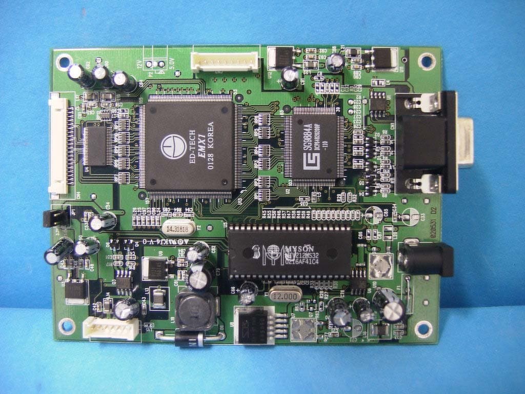
PC3GSM-141
Sep 11, 2002LCD Monitor
Equipment Class
JBP - Part 15 Class B Computing Device Peripheral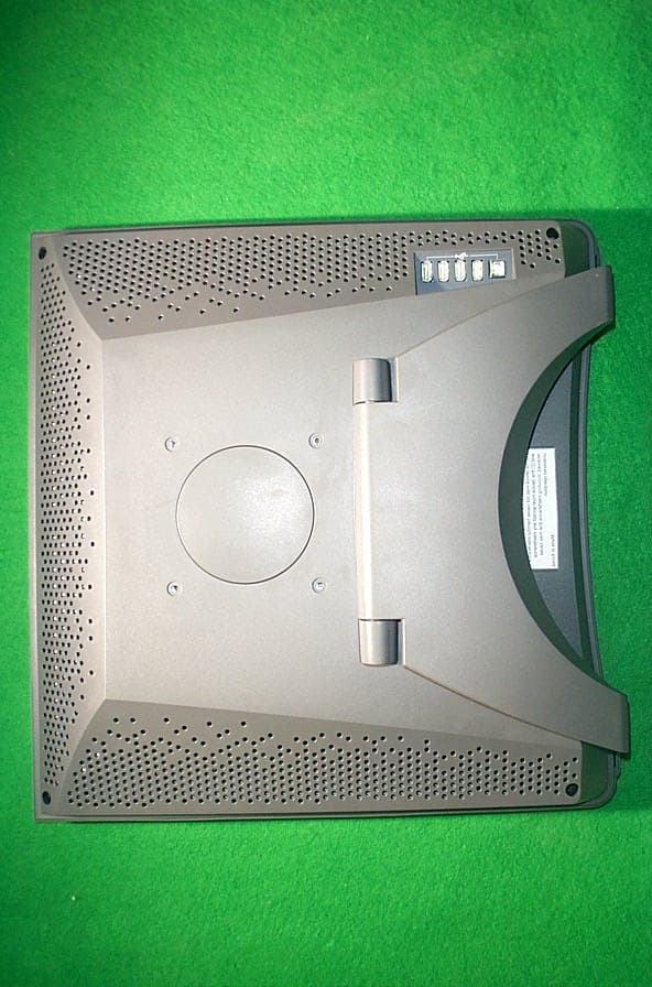
PC3GM-170
Dec 17, 2001TFT LCD Monitor
Equipment Class
JBP - Part 15 Class B Computing Device Peripheral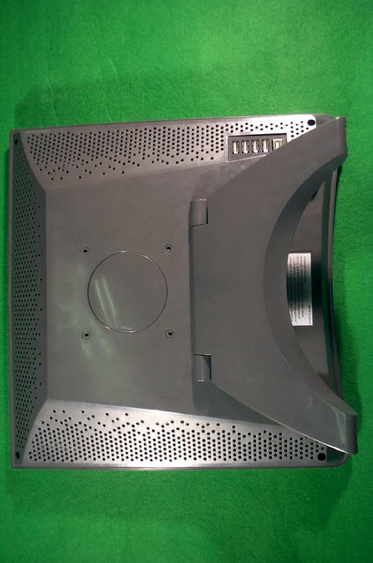
PC3GM-181
Dec 12, 2001TFT LCD Monitor
Equipment Class
JBP - Part 15 Class B Computing Device Peripheral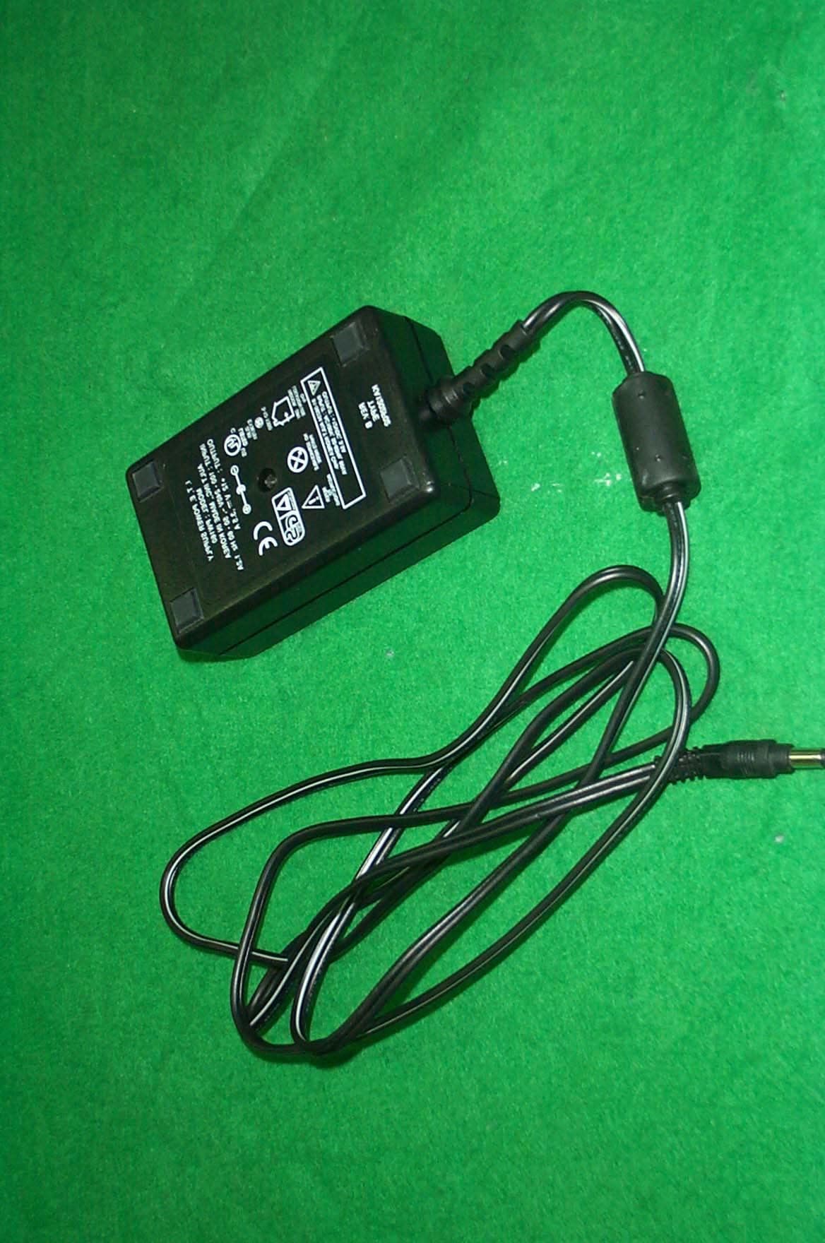
PC3GM-160
Apr 24, 2001LCD Monitor
Equipment Class
JBP - Part 15 Class B Computing Device Peripheral