PC3GM-160LCD Monitor
GTT Co., Ltd.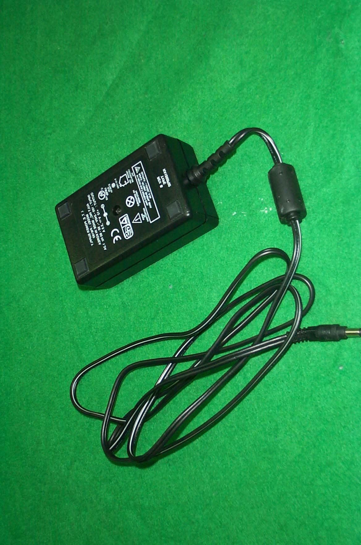
Click to zoom
Application Details
- Equipment Class
- JBP - Part 15 Class B Computing Device Peripheral
- Date of Grant
- Apr 24, 2001
- Application Purpose
- Original Equipment
- Date of Application
- Apr 24, 2001
- Equipment Note
- LCD Monitor
- Company
- GTT Co., Ltd.
- Country
- South Korea
Documents & Files
Document Text
Text extracted from the exhibit documents filed with the FCC. Open a document above to read the original.
Users Manual
CONTENTS 1. Package Contents 2. Monitor Parts 3. Connecting to PC 4. Features 5. OSD Menu functions 6. AV OSD function (Optional) 7. Dimension 8. Specification 9. USB function (Optional) 10. Pivot function (Optional) 11. Recommended Use 12. Troubleshooting Package Contents Your TFT-LCD monitor box should contain the following : STANDARD PARTS • TFT-LCD monitor • DC Power adapter - Connects to DC IN port on the base of monitor • Power cord - Connects wall outlet to DC Power adapter • D-SUB 15pin video cable - Connects PC to LCD monitor • Stereo audio cable - Connects PC sound card to audio input port on the base of monitor • User's manual OPTIONAL PARTS • USB upstream cable - Connects PC to USB ports on the base of monitor • Video cables (Composite, S-video) • Audio cable for AV monitor • Pivot software - Must be installed to use the monitor in Portrait mode Monitor Parts 1. Power switch 1. Power switch1. Power switch 1. Power switch 2. Speaker hole 3. OSD button 4. Power input connector 5. LED indicator 6. USB Up stream connector7. USB Down stream connectors 8. Audio OUT port 9. Audio IN port 9. Audio IN port9. Audio IN port 9. Audio IN port 10. Volume control 11. Power input connect 12. VGA input connector 13. Composite input connector 13. Composite input connector13. Composite input connector 13. Composite input connector 14. S-Video input connector 15. Cable hole z 6.7.13.14 parts are optiona 6.7.13.14 parts are optiona6.7.13.14 parts are optiona 6.7.13.14 parts are optional ll l Connecting to PC To attach your TFT-LCD monitor to your system, follow the instructions hereunder 1. Connect the small DC power cord from the base of the monitor to the head (For first time installation, this step will be completed by the factory) 2. Connect 15-pin D-SUB cable to the connector or display card of your computer system. Tighten all the screws 3. Connect 15-pin D-SUB cable to the appropriate connectors on the back of the monitor head 4. Connect AC adapter cable to the power input connectors on the back of the monitor base 5. Connect one end of the power cord to the AC adapter and the other end to the power outlet 6. Turn on the monitor 7. To complete the setup A. set up your computer system to : 1280 x 1024 resolution @ 60Hz. B. Use the following OSD controls - Auto adjust control - Phase •Adjustment of the H/V Position controls may be required to complete setup of your TFT- LCD monitor. For a full description of these OSD controls, refer to OSD menu functions •Your monitor has two 3 Watt speakers with amplifier. Please connect the speaker jack to the Line out jack of your PC's sound card Features TFT-LCD (Thin film transistor - liquid crystal display) The 15.7” inch panel and hard coating(3H),anti-glare treatment of the front polarizer enables low reflection, anti-static, high – resolution and high-contrast characteristics. Plug-and-Play Compatible This TFT-LCD monitor conforms to the VESA(Video Electronics Standards Association) standard and DDC1/DDC2B. A picture adjustment function makes it possible to adjust the image quality to match the input signal. An automatic size adjustment function is provided Auto-setup control on OSD screen adjust image position, horizontal size or fine settings. Environmentally Friendly The power consumption can be reduced by using this TFT-LCD monitor in combination of a computer that conforms to the VESA DPMS(Display Power Management Signaling) standard. Desk space can be used effectively due to the 20 cm depth. VESA standard wall mounting This TFT-LCD monitor has the VESA (Video Electronics Standards Association) standard wall mounting holes Monitor head can be mounted on the wall using a VESA-compliant wall mount. OSD menu functions OSD (On-Screen-Display) control buttons functions as follows : To access OSD Menu, press MENU button 1.Press the MENU button to display the main menu shown below 2.Press the MOVE button to move the highlighted area down 3.Press the MENU button to enter the submenu 4.Press the MOVE button to select the menu you with to change 5.Press the UP/DOWN button to change the settings 6.After making adjustments, press the MENU button to save changes and exit the menu [AUTO] • Auto adjust Automatically adjust Image Position, Horizontal Size or Fine setting [PICTURE] •BrightnessControls the brightness of the LCD • Contrast Controls the contrast of the LCD H PositionControls the Horizontal image position within the display of the LCDV PositionControls the Vertical image position within the display of the LCD • Phase Improves focus, clarity and image stability [ADVANCED] •Sharpness Adjust the clarity and focus of the screen image Each setting is adjusted at the factory Sharp 1 à 2 à 3 à 4 à 5 Soft Color TemperatureProvides four preset color adjustments Each color setting is adjusted at the factory 5000 à 7300 à 9300 à user (To control each color, select user setting) [OPTIONS] OSDProvides nine preset OSD positions Each position is fixed at the factory OSD H / V posControls the position of OSD •Language •More options (Source scan) Select the source scan mode between ON and OFF [UTILITIES] •OSD timeout You can select how long the monitor waits after the last touch of a button to shout off the OSD control menu OSD backgroundControls the color of OSD background -Opaque (gray), Translucent (transparent) Factory resetAllows you to reset all OSD control settings back to the factory settings USB Function (Optional) You can attach USB peripheral devices (mouse, keyboard, etc.) To complete the USB installation, do the following:1.Connect the USB cable from the computer to the USB IN jack on the rear of the base. 2.Plug the USB peripheral devices into any downstream port on the rear of the base Pivot (Optional) -Landscape (horizontal) mode, like on most existing monitors, is great for spreadsheets or computer games. -Portrait (vertical) mode is the form factor of most documents we use daily in the office and on the Internet To switch from landscape (default)…
Text truncated - open the document above for the full version.
Block Diagram
5 5 4 4 3 3 2 2 1 1 DD CC BB AA GTT Co,. Ltd DEN 900-0014-00A BLOCK DIAGRAM B 110Tuesday, April 17, 2001 Title SizeDocument NumberRev Date:Sheetof LVDS DHS DVS DEN DRE[7:0] DGE[7:0] DBE[7:0] DBO[7:0] DRO[7:0] DGO[7:0] DCLK LVDS_PWDN VIDEO DEC SCL SDA DEC_OE VHS VVS VCLK VB[7:0] VG[7:0] VFIELD VPEN IC_PWON ADC GCLK GPENSOG GBO[7:0] GBE[7:0] GGO[7:0] GGE[7:0] GRO[7:0] GRE[7:0] SCL GCOAST GBLKSPL GLOCK GFBK GHS GVS SDA IC_PWON FLASH ROM SCL ROM_WEBOOT_WEROM_OESDAD[15:0] A[19:1] VPP_EN MISC TXD RXD DCKEXT MCKEXT CS1 RESET NMI A0 BHEN CLKEN ROM_WE WR D[7:0] PW164R VCLK VG[7:0] VB[7:0] GHS GCLK GRE[7:0] GBO[7:0] GPENSOG GBE[7:0] GGO[7:0] GRO[7:0] GVS GGE[7:0] DGE[7:0] DBE[7:0] DRO[7:0] DEN DVS DGO[7:0] DRE[7:0] DBO[7:0] DCLK GLOCK GBLKSPL GCOAST NMI D[15:0] TX D MCKEXT SDA RXD IRRCVR0 RESETDCKEXT DHS A[19:1] SCL ROM_WEROM_OE CS1 VFIELD GFBK VPP_EN BOOT_WE DEC_OE CLKEN LVDS_PWDN VPEN VVS VHS BHEN A0 WR IC_PWON VG[7:0] VB[7:0] GBO[7:0] GBE[7:0] GRE[7:0] GGE[7:0] A[19:1]D[15:0] D[7:0] GGO[7:0] GRO[7:0] DVS VHS VPEN VCLK GBLKSPL DEC_OE VVS VFIELD GCLK GVS GPENSOG SDA SCL ROM_OEVPPENBOOT_W E CLKEN MCKEX T A0 NMI TX D DCKEXT CS1RESET RXD BHENWR ROM_WE DCLK DHS GFBK GHS GLOCK GCOAST
External Photos
SK TECH CO., LTD. Page 1 of 4 SKT SKTOS-01053 FCC ID : PC3GM-160 External Photographs of EUT SK TECH CO., LTD. Page 2 of 4 SKT SKTOS-01053 FCC ID : PC3GM-160 SK TECH CO., LTD. Page 3 of 4 SKT SKTOS-01053 FCC ID : PC3GM-160 SK TECH CO., LTD. Page 4 of 4 SKT SKTOS-01053 FCC ID : PC3GM-160
ID Label/Location Info
SK TECH CO., LTD. Page 1 of 1 SKT SKTOS-01053 FCC ID : PC3GM-160 FCC ID Sample Label & Location Information LABELLING REQUIREMENTS PER ∫∫∫∫ ∫∫∫∫∫∫∫∫ ∫∫∫∫2.928 The Label shown shall be permanently affixed at a conspicuous location on the device and be readily visible to the user at the time of purchase. FCC ID : PC3GM-160 This device complies with part 15 of the FCC Rules. Operation is subject to the following two conditions: (1) This device may not cause harmful interference, and (2) this device must accept any interference received, including interference that may cause undesired operation.
Internal Photos
SK TECH CO., LTD. Page 1 of 6 SKT SKTOS-01053 FCC ID : PC3GM-160 Internal Photographs of EUT SK TECH CO., LTD. Page 2 of 6 SKT SKTOS-01053 FCC ID : PC3GM-160 SK TECH CO., LTD. Page 3 of 6 SKT SKTOS-01053 FCC ID : PC3GM-160 SK TECH CO., LTD. Page 4 of 6 SKT SKTOS-01053 FCC ID : PC3GM-160 SK TECH CO., LTD. Page 5 of 6 SKT SKTOS-01053 FCC ID : PC3GM-160 SK TECH CO., LTD. Page 6 of 6 SKT SKTOS-01053 FCC ID : PC3GM-160
Test Report
SK TECH CO., LTD. Page 1 of 13 SKT SKTOS-01053 FCC ID : PC3GM-160 Certificate of Compliance Test Report No.: SKTOS-01053 NVLAP CODE : 200220-0 Applicant: GTT CO., LTD. Applicant Address: Suite 509, Pungsan Apt. Factory, 1141-2, Baeksuk-dong, Ilsan-gu, Koyang-shi, Kyounggi-do, 411-360, Korea Product: LCD Monitor FCC ID: PC3GM-160 Model No.: GM-160 Receipt No.: SKE20010404-263 Date of receipt: Apr. 04, 2001 Date of Issue: Apr. 17, 2001 Testing location: SK TECH CO., LTD. 820-2, Wolmoon-Ri, Wabu-Up, Namyangju-Si, Kyunggi-Do, Korea Test Standards: ANSI C63.4 / 1992 Rule Parts: FCC part 15 Subpart B Equipment Class : Class B Digital Device Peripheral Test Result: The above mentioned product has been tested and passed. Prepared by:E.K.Seong Tested by:K.W.Song/Engineer Approved by: J.Y.Hyun /Lab.Manager Signature Date Signature Date Signature Date Other Aspects : Abbreviations : · OK, Pass = passed · Fail = failed · N/A = not applicable ☞ ☞☞ ☞ •This test report is not permitted to copy partly without our permission. •This test result is dependent on only equipment to be used. •This test result is based on a single evaluation of one sample of the above mentioned. •This test report must not be used by the client to claim product endorsement by NVLAP or any agency of the U.S Government. • We certify that this test report has been based on the measurement standards that is traceable to the national or International standards. NVLAP Lab. Code: 200220-0 SK TECH CO., LTD. Page 2 of 13 SKT SKTOS-01053 FCC ID : PC3GM-160 》》 》》》》 》》 Contents 《《 《《《《 《《 Contents 2 List of Tables 2 List of Figures 2 List of Photographs 2 1. General 3 2. Test Site 3 2.1 Location 3 2.2 List of Test and Measurement Instruments 4 2.3 Test Date 4 2.4 Test Environment 4 3. Description of the tested samples 5 3.1 Rating and Physical Characteristics 5 3.2 Submitted Documents 5 4. Measurement Conditions 6 4.1 Modes of Operation 6 4.2 List of Peripherals 6 4.3 Type of Used cables 7 4.4 Test Setup 7 4.5 Uncertainty 7 5. EMISSION Test 8 5.1 Conducted Emissions 8 5.2 Radiated Emissions 12 》 》》 》List of Tables Table 1 List of test and measurement Equipment 4 Table 2 Test Data, Conducted Emissions 11 Table 3 Test Data, Radiated Emissions 13 》 》》 》List of Figures Figure 1 Spectral Diagram, LINE-PE 9 Figure 2 Spectral Diagram, Neutral-PE 10 SK TECH CO., LTD. Page 3 of 13 SKT SKTOS-01053 FCC ID : PC3GM-160 1. General This equipment has been shown to be capable of compliance with the applicable technical standards and was tested in accordance with the measurement procedures as indicated in this report. We attest to the accuracy of data. All measurements reported herein were performed by SK Tech Co., Ltd. and were made under Chief Engineer’s supervision. We assume full responsibility for the completeness of these measurements and vouch for the qualifications of all persons taking them. 2. Test Site SK TECH Co., Ltd. 2.1 Location 820-2, Wolmoon Ri, Wabu-Up, Namyangju-Si, Kyunggi-Do, Korea The test site is in compliance with ANSI C63.4/1992 for measurement of radio interference. SK TECH CO., LTD. Page 4 of 13 SKT SKTOS-01053 FCC ID : PC3GM-160 2.2 List of Test and Measurement Instruments Table 1 : List of Test and Measurement Equipment z Conducted Emissions Kind of Equipment Type S/N Calibrated until EMI Receiver ESHS10 862970/019 04.2001 Artificial Mains Network KNW-407 M63284 07.2001 EMI Receiver ESHS10 385871/002 11.2001 Artificial Mains Network ESH3-Z5 836679/018 11.2001 Conducted Cable N/A N/A 07.2001 z Radiated Emissions Kind of Equipment Type S/N Calibrated until EMI Receiver ESVS 10 825120/013 04.2001 Spectrum Analyzer R3361A 11730187 07.2001 Amplifier 8447F 3113A05153 05.2001 Log Periodic Antenna UHALP9107 91071238 04.2001 Biconical Antenna BBA9106 N/A 04.2001 Open Site Cable N/A N/A 07.2001 Antenna Mast 5907 N/A N/A Antenna & Turntable controller 5906 91X519 N/A Amp & Receiver connection cable N/A N/A 07.2001 Amp & Spectrum connection cable N/A N/A 07.2001 50Ω Switcher MP59B M93083 07.2001 2.3 Test Date Date of Application : Apr. 04, 2001 Date of Test : Apr. 14, 2001 2.4 Test Environment See each test item’s description. SK TECH CO., LTD. Page 5 of 13 SKT SKTOS-01053 FCC ID : PC3GM-160 3. Description of the tested samples The EUT is LCD MONITOR. 3.1 Rating and Physical Characteristics Type Amorphous active matrix TFT-LCD Active area 15.7” diagonal Pixel format 1280(H) x 1024(V) Pixel pitch 0.243mm x 0.243mm Color depth 8 bit, 16M colors Brightness 200cd/ m 2 Display size 311.040mm x 248.832mm Viewing angle U/D: 45 ̊/45 ̊, R/L : 60 ̊/60 ̊ Interface LVDS Backlight 2CCFT Panel Contrast ratio 250:1(Typ.) Resolution Support SXGA 1280 x 1024(max) Power Consumption On working Off <30 watt <4watt Plug & Play DDC1/DDC2B Power Saving VESA DMPS Power Supply Adapter Input Output AC 100V ~ 240V, 50~60Hz 12V DC 3.2 Submitted Documents N/A SK TECH CO., LTD. Page 6 of 13 SKT SKTOS-01053 FCC ID : PC3GM-160 4. Measurement Conditions Operating of EUT voltage is 12V DC supplied by the adaptor which is structural element for EUT. ( Adaptor Input Voltage : AC 120V, 60Hz) 4.1 Modes of Operation The EUT was in the following operation mode during all testing; EUT is connected with PC by video interface cable. Test is made on the mode of scrolling “H” and playing audio file. 4.2 List of Peripherals Description Manufacturer Model Name Serial No. FCC ID Printer H.P 2225C 3245S12493 DSI6XU2225 Keyboard LG-IBM LKB-0107 90602892 N/A Mouse 1 Logitech M-S48 LZA91450139 DZL211153 Mouse 2 Logitech M-BE55 LZE02551778 DoC Mouse 3 A4 Tech AM-5E 951237243 H8GAM555P Speaker FAN HAI DIAN CMK660 N/A DoC Mic LG Electronics N/A N/A N/A Adaptor (for EUT) AULT INC PW160 N/A N/A Personal Computer Mother board Micro-Star MS-6161 96K6262664G1144716 DoC Power supply HIPRO HP-235ATXA6 F3-9911252206 DoC FDD Drive Panasonic JU-257A604P 62638 DoC HDD Quantum Pro Drive LPS 9442203B DoC CD-ROM Drive LG GCD-R560B 6023002365 BEJGCD-R560B SK TECH CO., LTD. Page 7 of 13 SKT SKTOS-01053 FCC ID …
Text truncated - open the document above for the full version.
Test Setup Photos
SK TECH CO., LTD. Page 1 of 2 SKT SKTOS-01053 FCC ID : PC3GM-160 Test set up photos Photograph 1: Setup for Conducted Emissions SK TECH CO., LTD. Page 2 of 2 SKT SKTOS-01053 FCC ID : PC3GM-160 Photograph 2: Setup for Radiated Emissions
Contact Information
Applicant
Smith Cheon(Senior Engineer)
Test Firm
SK Tech Co., Ltd.Jae-Yeong Hyun
Technical Specifications
| # | Rule Parts | Frequency Range | Power Output |
|---|---|---|---|
| 1 | 15B | - | - |
Other Applications from GTT Co., Ltd.
PC3GSM-141
Sep 11, 2002LCD Monitor
Equipment Class
JBP - Part 15 Class B Computing Device Peripheral
PC3GM-170
Dec 17, 2001TFT LCD Monitor
Equipment Class
JBP - Part 15 Class B Computing Device Peripheral
PC3GM-181
Dec 12, 2001TFT LCD Monitor
Equipment Class
JBP - Part 15 Class B Computing Device Peripheral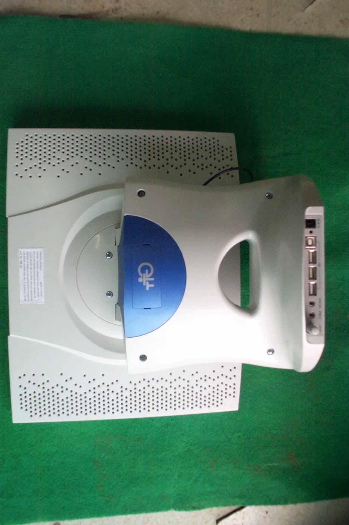
PC3GM-151
Nov 26, 2000TFT LCD Monitor
Equipment Class
JBP - Part 15 Class B Computing Device Peripheral