PC3GSM-141LCD Monitor
GTT Co., Ltd.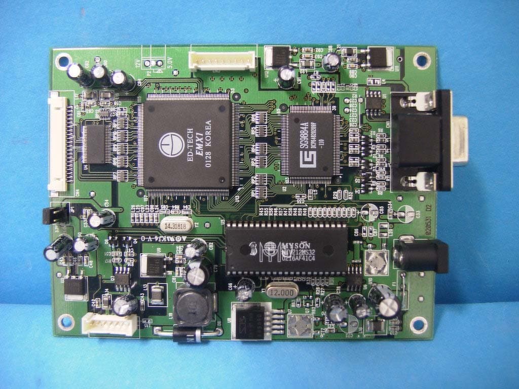
Click to zoom
Application Details
- Equipment Class
- JBP - Part 15 Class B Computing Device Peripheral
- Date of Grant
- Sep 11, 2002
- Application Purpose
- Original Equipment
- Date of Application
- Sep 11, 2002
- Equipment Note
- LCD Monitor
- Company
- GTT Co., Ltd.
- Country
- South Korea
Documents & Files
Document Text
Text extracted from the exhibit documents filed with the FCC. Open a document above to read the original.
Users Manual
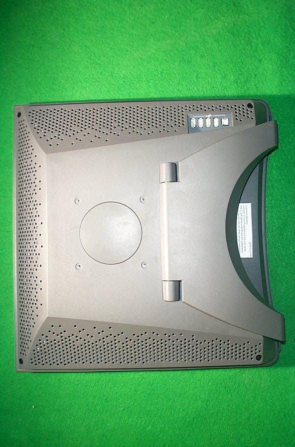
User’s Manual TFT-LCD monitor Ver. 1.0 CONTENTS Package Contents Monitor Parts Connecting to PC Recommended Use Features OSD Menu functions Advanced Features Specification Dimension Troubleshooting 3 Thank you for your selection of new TFT LCD Monitor. Please take a few minutes to read this User’s manual for the best performance of this monitor. Information in this manual is subject to change without prior notice for improving design, function and etc. IBM, DOS, PC and VGA are trademarks of International Business Machines Corporation. 4 5 6 7 8 9 13 14 15 16 54 Package Contents Your TFT-LCD monitor box should contain the following : Monitor Parts STANDARD PARTS •TFT-LCD monitor •DC Power adapter -Connects to DC IN port on the base of monitor •Power cord -Connects wall outlet to DC Power adapter •D-SUB 15pin VGA cable -Connects PC to LCD monitor •User's manual 1. OSD control button 2. Power button & LED indicator 3. Speaker holes(Speakers are optional) 4. VESA standard hole(75mm x 75mm) 5. Power input connector 6. D-SUB 15 pin VGA input connector 7. Audio IN port 8. Touch interface connector(USB interface or serial interface) * 7. 8. parts are optional FRONTREAR 3 4 A 5678 A-1 12 A-2 USB Type Serial Type OPTIONAL PARTS •Stereo audio cable -Connects PC sound card to audio input port on the monitor •Touch software -Touch installation driver •Touch interface cable -USB cable or serial cable -Connects PC to LCD monitor 76 Connecting to PC To attach your TFT-LCD monitor to your system, follow the instructions hereunder 1. Connect 15-pin D-SUB cable to the connector or display card of your computersystem. Tighten all the screws 2. Connect 15-pin D-SUB cable to the appropriate connectors on the back of themonitor head 3. Connect AC adapter cable to the power input connectors on the back of the monitor head 4. Connect one end of the power cord to the AC adapter and the other end to the power outlet 5. Turn on the monitor 6. To complete the setup A. set up your computer system to : 1024 x 768 resolution @ 60Hz. B. Use the following OSD controls -Auto adjust control -Coarse or Clock Phase control ?Adjustment of the H/V Position and Image Adjust H. Size controls may be required to complete setup of your TFT-LCD monitor. For a full description of these OSD controls, refer to OSD menu functions FOR OPTIMUM PERFORMANCE, PLEASE NOTE THE FOLLOWING WHEN SETTING UP AND USING THE TFT-LCD MONITOR. Recommended Use FOR OPTIMUM PERFORMANCE, PLEASE NOTE THE FOLLOWING WHEN SETTING UP AND USING THE TFT-LCD MONITOR. • • DO NOT OPEN THE MONITOR DO NOT OPEN THE MONITOR. opening or removing covers may expose you to dangerous shock hazards or other risks. Once you open it the warranty voids. •Do not put anything on top of the monitor. •Do not spill any liquids into the cabinet or use your monitor near water. •Do not place this product on a sloping or unstable cart, stand or table, as the monitor may fall, causing serious damage to the monitor. •If you connect or disconnect the VGA cable while both of PC’s and LCD monitor’s power is turned on, the monitor might show some garbage on the screen or could be damaged. Please turn off the TFT-LCD monitor’s power before connect or disconnect VGA cable. •Handle with care when transporting. Save packaging for transporting. •Do not touch or press the surface of the LCD panel, it will cause a permanent damage. Use only soft cloth with non-ammonia glass cleaner to clean the panel. 8 Features TFT-LCD (Thin film transistor -liquid crystal display) The XGA panel and hard coating(3H), anti-glare treatment of the front polarizerenables low reflection, anti-static, high- resolution and high-contrast characteristics. Plug-and-Play Compatible This TFT-LCD monitor conforms to the VESA (Video Electronics Standards Association) standard and DDC1/DDC2B. A picture adjustment function makes it possible to adjust the image quality to match the input signal. An automatic size adjustment function is provided Auto-setup control on OSD screen adjust image position, horizontal size or fine settings. Environmentally Friendly The power consumption can be reduced by using this TFT- LCD monitor in combination of a computer that conforms to the VESA DPMS(Display Power Management Signaling) standard. Desk space can be used effectively due to the 20cm depth. VESA standard wall mounting This TFT-LCD monitor has the VESA (Video Electronics Standards Association) standard wall mounting holes. Monitor head can be mounted on the wall using a VESA compliant wall mount. OSD menu functions 9 MENU : Menu on/move button -Show OSD menu on the screen. Moves the highlighted area right to select one of the functions EXIT: Menu off button -Exit from OSD menu. Exit to main menu from sub menu. DOWN : Adjust button -Moves the bar left to decrease the adjustment. -Enter the submenu. UP:Adjust button -Moves the bar right to increase the adjustment. -Enter the submenu. OSD (On-Screen-Display) control functions as follows : To access OSD Menu, press MENU button [ MAIN MENU DISPLAY ] MENU MENU + + EXIT EXIT 1110 Controls the brightness of the LCD Use UP or DOWN button to increase or decrease the setting Controls the contrast of the LCD Use UP or DOWN button to increase or decrease the setting Controls the horizontal image position within the display of the LCDUse the UP or DOWN button to move the image right or left Controls the vertical image position within the display of the LCD Use the UP or DOWN button to move the image up or down Automatically adjust Image Position, Horizontal Size orFinesetting Press UP or DOWN button to adjust the settings automatically •BRIGHTNESS •CONTRAST •H-POSITION •V-POSITION Improves focus, clarity and image stability Use UP or DOWN button to increase or decrease the setting •CLOCK PHASE (Fine Tuning) Press the UP or DOWN button to enter into the following submenu •COLOR Press the MENU button toselect the item you wish to change Color temperature Provides two preset color adjustment : 6500K and 9300…
Text truncated - open the document above for the full version.
Block Diagram
5 5 4 4 3 3 2 2 1 1 DD CC BB AA AC INLET 100~240V 50/60Hz LCD PANEL N141X202 INVERTE R INVERTER CABLE OSD CABLE OSD, POWER BOARD SIGNAL CABLE D-SUB Input Video Rate H:30~62KHz, V:56~75Hz 24C21 ADC SG9884 MTV212MS32 Scaler EMX1 LVDS SN75LVDS84 R,G,B 6bit Wafer 3.3V R,G,B 6bit H/V SYNC DCLK ENABLE R,G,B 24DCLK RGB SIGNALH/V SYNC 14.318MHz 12.00MHz INVERTER ON/OFF H/V SYNC MAIN BOARD Input Video Rate H:48~62KHz, V:60~75Hz Resolution : 1024*768 Dclk : 65MHz Output Rating : 12V ,3A
Test Report
File No. 02-IST-186/FB IST EMC LAB. Page 1 of 16 IST EMC Lab. San 21-8 Goan-Ri, Baekam-Myun, Yongin-Si, Kyunggi-Do, KOREA International - Tel : 82-31 - 333 - 4093. Fax : 82-31 - 333 - 4094. Domestic - Tel : 031 - 333 - 4093. Fax : 031 - 333 - 4094. IST EMC LAB. EMISSION TEST REPORT Test report file No. : 02-IST-186/FB Date of issue : Aug. 28, 2002 Model / Type No. : GSM-141 ■ Basic □ Alternate Kind of product Brand name Applicant Manufacturer License holder Address : LCD Monitor : GTT : GTT Co., Ltd. : GTT Co., Ltd. : GTT Co., Ltd. : Suite 509, Pungsan Apt. Factory, 1141-2, Baeksok-dong, Ilsan-gu, Kyonggi-Do, Korea Test result according to the regulation(s) Positive Negative at page 3. This test report with appendix consists of 16 pages. The test result only responds to the tested sample. It is not allowed to copy this report even partly without the allowance of the Test Laboratory. This equipment is complied with the applicable technical standards as indicated in the measurement report and was tested in accordance with the measurement procedures specified in ANSI C63.4-1992. File No. 02-IST-186/FB IST EMC LAB. Page 2 of 16 IST EMC Lab. San 21-8 Goan-Ri, Baekam-Myun, Yongin-Si, Kyunggi-Do, KOREA International - Tel : 82-31 - 333 - 4093. Fax : 82-31 - 333 - 4094. Domestic - Tel : 031 - 333 - 4093. Fax : 031 - 333 - 4094. DIRECTORY A) Documentation. Page Directory Test regulations Information of Test Regulation Equipment under Test Test Conditions Test Result Test-setup Summary 2 3 3 4 5 ~ 6 7 8 ~ 10 16 B) Test Data. Conducted emissions (Mains) Radiated emissions : 450 kHz - 30 MHz : 30 MHz – 1 GHz 11 ~ 13 14 ~ 15 C) Appendix File No. 02-IST-186/FB IST EMC LAB. Page 3 of 16 IST EMC Lab. San 21-8 Goan-Ri, Baekam-Myun, Yongin-Si, Kyunggi-Do, KOREA International - Tel : 82-31 - 333 - 4093. Fax : 82-31 - 333 - 4094. Domestic - Tel : 031 - 333 - 4093. Fax : 031 - 333 - 4094. TEST REGULATIONS The tests were performed according to the following regulations ; ■ - FCC Part 15, Subpart B (Unintentional Radiators, Class B) Information of Test Laboratory IST EMC Lab. San 21-8 Goan-Ri, Baekam-Myun, Yongin-Si, Kyunggi-Do, Korea International - Tel : 82-31 - 333 - 4093. Fax : 82-31 - 333 - 4094. Domestic - Tel : 031 - 333 - 4093. Fax : 031 - 333 - 4094. File No. 02-IST-186/FB IST EMC LAB. Page 4 of 16 IST EMC Lab. San 21-8 Goan-Ri, Baekam-Myun, Yongin-Si, Kyunggi-Do, KOREA International - Tel : 82-31 - 333 - 4093. Fax : 82-31 - 333 - 4094. Domestic - Tel : 031 - 333 - 4093. Fax : 031 - 333 - 4094. EQUIPMENT UNDER TEST Equipment Description : LCD Pannel : Active area: 14.1 inch, Pixel Pitch: 0.297 x 0.297 mm Amorphous active matrix TFT-LCD N141X202 (Maker: Chi Mei Optoelectronics Corp.) Frequency Range : Vertical: 50 ~ 160 Hz, Horizontal: 30 ~ 95 kHz Plug and Play : VESA Compatible Dimensions (W x H x D) : 326.4 x 264.3 x 166.3 (set with stand) Power consumption : Under 30 W Power Supply (Adapter) : AD-40A (Maker: ARITECH Co.,Ltd.) Input : 100 ~ 240 Vac, 1.0A (Max.), 50/60 Hz Output : 12 Vdc, 3.0 A EUT Type : Table-Top. Floor-Standing. Table-Top and Floor-Standing(Combination). Operation – mode of the E.U.T. : The equipment under test was operated during the measurement under following conditions : Standby. Operational Condition : Scrolling “H” characters under MS Windows 98, Test mode : 1024 X 768, 75 Hz Configuration of the equipment under test : Equipment Type Brand Serial No PC Brio BA600/550 HP SG01603779 Keyboard SK-2502C HP M000456820 Printer A0302384 Northern Telecom 25L9S60856 Mouse1 M-S48A HP LZA01051466 Mouse2 M-M28 Logitech LCA53305547 Connecting Interface Cables : - Unshielded AC power cable : 1.8 m - Shielded monitor’s signal cable : 1.7 m - Shielded printer’s signal cable : 1.8 m - Unshielded AC power cable for Adapter : 1.7 m - Unshielded DC power cable for Adapter : 1.4 m - Unshielded speaker’s signal cable of monitor : 1.4 m File No. 02-IST-186/FB IST EMC LAB. Page 5 of 16 IST EMC Lab. San 21-8 Goan-Ri, Baekam-Myun, Yongin-Si, Kyunggi-Do, KOREA International - Tel : 82-31 - 333 - 4093. Fax : 82-31 - 333 - 4094. Domestic - Tel : 031 - 333 - 4093. Fax : 031 - 333 - 4094. TEST CONDITIONS The measurement of the conducted emissions (Interference voltage) was performed in a shielded room. Test location : Shielded room. No.1 Compact chamber 2 Used testing instruments : Name Type Manufacturer Calibration. Date Serial Number ESH 3 Test Receiver Rohde & Schwarz Jul. 25, 2002 892108/018 3725/2 LISN EMCO Aug. 22, 2002 9101-2068 KNW-407 LISN Hyup-Rip Aug. 21, 2002 8-883-10 ESH 3-Z2 Pulse Limiter Rohde & Schwarz Jul. 25, 2002 357.8810.52 Test - accessories : Type Manufacturer Aneroid Barometer Sato Hygrometer Sato Measurement Procedures : Conducted emissions measurments were made in accordance with ANSI C-63.4-1992, “Method of Measurement of Radio-Noise Emissions from Low-Voltage Electrical and Electronic Equipment in the Range of 9 kHz to 40 GHz”. The measurement were performed over the frequency range of 0.45MHz to 30MHz using a 50 Ω /50uH LISN as the input transducer to an EMI/Field Intensity Meter. The measurements were made with the detector set for “Peak” amplitude within an IF bandwidth of 10kHz or for “quasi-peak” within a bandwidth of 9kHz. All used test-instruments as well as the test-accessories are calibrated regularly. File No. 02-IST-186/FB IST EMC LAB. Page 6 of 16 IST EMC Lab. San 21-8 Goan-Ri, Baekam-Myun, Yongin-Si, Kyunggi-Do, KOREA International - Tel : 82-31 - 333 - 4093. Fax : 82-31 - 333 - 4094. Domestic - Tel : 031 - 333 - 4093. Fax : 031 - 333 - 4094. The measurement of the radiated emissions (Electric field) in the frequency range from 30 MHz to 1GHz was performed in horizontal and vertical antenna polarization at a open-site which meet the site attenuation requirement of ANSI C63.4-1992 and a test distance of : Location : Open Site No. 1 Open Site No. 2 Open Site No. 3 Distance : 3 meters 10 meters Used testing instruments : Name Type Manufacturer Calibration. Date Seria…
Text truncated - open the document above for the full version.
Contact Information
Applicant
Smith Cheon(Senior Engineer)
Test Firm
IST Co., LtdBong Kyoon Bae
Technical Specifications
| # | Rule Parts | Frequency Range | Power Output |
|---|---|---|---|
| 1 | 15B | - | - |
Other Applications from GTT Co., Ltd.
PC3GM-170
Dec 17, 2001TFT LCD Monitor
Equipment Class
JBP - Part 15 Class B Computing Device Peripheral
PC3GM-181
Dec 12, 2001TFT LCD Monitor
Equipment Class
JBP - Part 15 Class B Computing Device Peripheral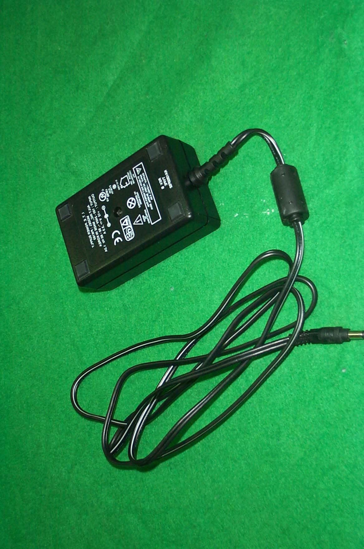
PC3GM-160
Apr 24, 2001LCD Monitor
Equipment Class
JBP - Part 15 Class B Computing Device Peripheral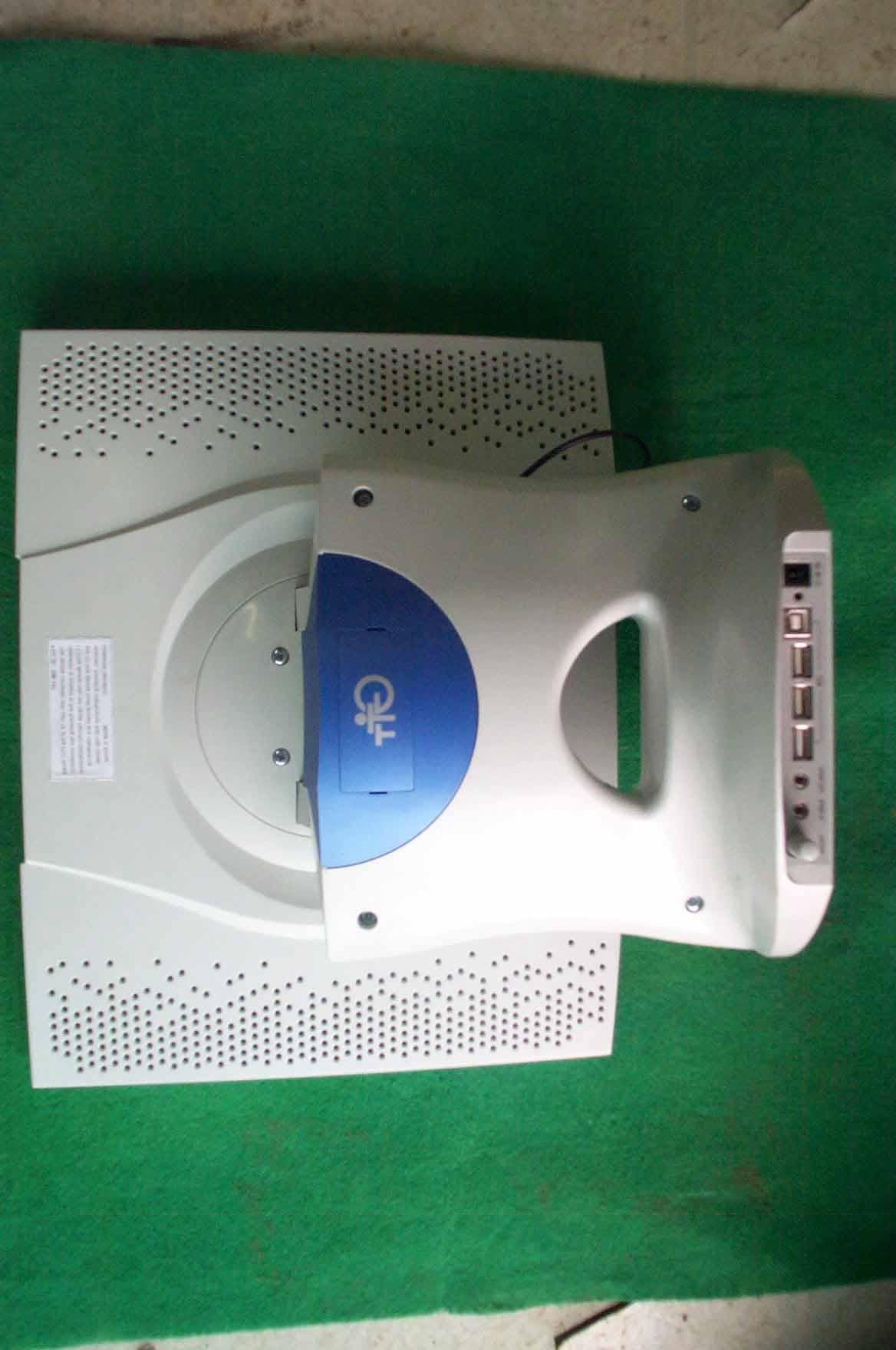
PC3GM-151
Nov 26, 2000TFT LCD Monitor
Equipment Class
JBP - Part 15 Class B Computing Device Peripheral