PC6CF-2031
Growell Telecom Co., Ltd.
Click to zoom
Application Details
- Equipment Class
- PCT - PCS Licensed Transmitter worn on body
- Date of Grant
- Jun 12, 2002
- Application Purpose
- Original Equipment
- Date of Application
- Jan 17, 2002
- Frequency Range
- 1851.25000000 - 1908.75000000
- Company
- Growell Telecom Co., Ltd.
- Country
- South Korea
Documents & Files
Document Text
Text extracted from the exhibit documents filed with the FCC. Open a document above to read the original.
Users Manual
For more information about RF exposure, please visit the FCC website at www.fcc.gov FCC RF EXPOSURE INFORMATION In August 1996 the Federal Communications Commission (FCC) of the United States with its action in Report and Order FCC 96-326 adopted an updated safety standard for human exposure to radio frequency electromagnetic energy emitted by FCC regulated transmitters. Those guidelines are consistent with the safety standard previously set by both U.S. and inte rnational standards bodies. The design of this phone complies with the FCC guidelines and these international standards. Use only the supplied or an approved antenna. Unauthor ized antennas, modifications, or attachments could impair call quality, damage the phone, or resu lt in violation of FCC regulations. Do not use the phone with a damaged antenna. If a damaged ant enna comes into contact with the skin, a minor burn may result. Please contact your local dealer for replacement antenna. Body-worn Operation This device was tested for typical body-worn operations with the back of the device kept 2.5 cm. from the body. To maintain compliance with FCC RF exposure requirement s, use only belt-clips, holsters or similar accessories that maintain a 2.5cm. separation distance between t he user’s body and the back of the device, including the antenna, whether extended or retracted. The use of other belt-clip/holster s and other non-tested accessories may not comply with FCC RF Exposur e requirements and should be avoided. WARNING! Read this information before using your phone
Users Manual
Sprint PCS CC-Phone Modem Components All CC-Phone Modem packages include the following components: > Quick Reference Guide > CD ROM containing the CC-Wiz, Driver and User’s Guide > Warranty Card > ACAdapter > This User Guide Sprint PCS Coverage The Sprint PCS CC-Phone Modem operates on the Sprint PCS Nationwide Network which serves more than 330 major metropolitan areas. For coverage information, see the Sprint PCS web site, w.sprintpcs. com Sprint PCS Customer Care For questions about using your Sprint PCS CC-Phone Modem, call Sprint PCS Customer Care at 1 -888-21 1-4PCS (4727) or see us at www . s p ri nt pcs . com CC-Phone Modem Basics P P Account Activation P Care and Maintenance Software Included with CC-Phone Modem This section provides a brief description of the software that comes with the Sprint PCS CC-Phone Modem and explains account activation. It also tells you how to care for your CC- Phone modem to ensure reliable operation. Before you can use the CC -Phone modem, you must: 1. Install the software 2. Insert the CC-Phone modem 3. Activate the modem, if it has not been pre-activated CAUTION: Do not insert the modem into a PC Card slot before installing the software.
Users Manual
For more information about RF exposure, please visit the FCC website at www.fcc.gov FCC RF EXPOSURE INFORMATION In August 1996 the Federal Communications Commission (FCC) of the United States with its action in Report and Order FCC 96-326 adopted an updated safety standard for human exposure to radio frequency electromagnetic energy emitted by FCC regulated transmitters. Those guidelines are consistent with the safety standard previously set by both U.S. and inte rnational standards bodies. The design of this phone complies with the FCC guidelines and these international standards. Use only the supplied or an approved antenna. Unauthor ized antennas, modifications, or attachments could impair call quality, damage the phone, or resu lt in violation of FCC regulations. Do not use the phone with a damaged antenna. If a damaged ant enna comes into contact with the skin, a minor burn may result. Please contact your local dealer for replacement antenna. Body-worn Operation This device was tested for typical body-worn operations with the back of the device kept 2.5 cm. from the body. To maintain compliance with FCC RF exposure requirement s, use only belt-clips, holsters or similar accessories that maintain a 2.5cm. separation distance between t he user’s body and the back of the device, including the antenna, whether extended or retracted. The use of other belt-clip/holster s and other non-tested accessories may not comply with FCC RF Exposur e requirements and should be avoided. WARNING! Read this information before using your phone Sprint PCS CC-Phone Modem Components All CC-Phone Modem packages include the following components: > Quick Reference Guide > CD ROM containing the CC-Wiz, Driver and User’s Guide > Warranty Card > ACAdapter > This User Guide Sprint PCS Coverage The Sprint PCS CC-Phone Modem operates on the Sprint PCS Nationwide Network which serves more than 330 major metropolitan areas. For coverage information, see the Sprint PCS web site, w.sprintpcs. com Sprint PCS Customer Care For questions about using your Sprint PCS CC-Phone Modem, call Sprint PCS Customer Care at 1 -888-21 1-4PCS (4727) or see us at www . s p ri nt pcs . com CC-Phone Modem Basics P P Account Activation P Care and Maintenance Software Included with CC-Phone Modem This section provides a brief description of the software that comes with the Sprint PCS CC-Phone Modem and explains account activation. It also tells you how to care for your CC- Phone modem to ensure reliable operation. Before you can use the CC -Phone modem, you must: 1. Install the software 2. Insert the CC-Phone modem 3. Activate the modem, if it has not been pre-activated CAUTION: Do not insert the modem into a PC Card slot before installing the software.
Cover Letter(s)
January 17, 2002 Federal Communications Commission Equipment Approval Services 7435 Oakland Mills Road Columbia, MD 21046 SUBJECT: YISO TELECOM CO., LTD. FCC ID: PC6CF-2031 Part 24 Certification Gentlemen: Attached herewith, on behalf of YISO TELCOM CO., LTD. is an application for Part 24 Certification of the following PCS CDMA Modem Card CF Type II: FCC ID: PC6CF-2031 TRADE / MODEL(s): CC PHONE / CF-2031, YM-2031U EUT TYPE: Licensed Portable Transmitter Worn on Body (PCT) Tx Freq. Range: 1851.25 — 1908.75 MHz (PCS CDMA) Rx Freq. Range: 1931.25 — 1988.75 MHz (PCS CDMA) Max. RF Output Power: 0.473 W EIRP PCS CDMA (26.751 dBm) Attached is the applicant’s Letter of Authorization, Confidentiality Request, measurement report data and plots, RF Exposure measurement report, FCC ID label and location, test setup photographs, internal and external photographs, block diagrams (confidential), schematic diagrams & circuit description (confidential), operational description (confidential), parts list & tune-up procedure (confidential), and the user's manual. Should you have any questions or comments concerning the above, please contact the undersigned. cc: YISO TELECOM CO., LTD.
Cover Letter(s)
April 23, 2002 Federal Communications Commission Equipment Approval Services 7435 Oakland Mills Road Columbia, MD 21046 Attn: Mr. Joe Dichoso SUBJECT: Yiso Telecom Co., Ltd. FCC ID: PC6YM-1031K 731 Confirmation No.: EA480482 Correspondence Reference No.: 22310 Request for Tech. Info.: 03/14/02 Dear Joe: Transmitted herewith, on behalf of Yiso Telecom Co., Ltd., is an amendment provided in response to the request for technical information dated March 14, 2001. 1. This device was device was designed to be installed into the Casio Cassiopeia Pocket PC. It was tested for SAR compliance in this configuration. Please refer to the photos for SAR and EIRP tests. The device is a PCMCIA card but does not support general use in other hand held and note book PCs at this time. 2. Please find the attached list of available accessories. 3. Please find the attached final version of the user’s manual. 4. The antenna may be used extended or retracted but an external antenna cannot be used. 5. Please find the attached SAR photos. 6. Please find attached SAR plots with the conversion factors used during the SAR test. 7. Please find the corrected page 9 of the SAR test report and SAR validation plot. We validated the system with PCS brain tissue and changed the liquid to muscle to perform the SAR test. The manufactures target data is attached. 8. Please find the print out of the measured tissue dielectric parameters. 9. We used the Generic twin flat phantom because out SAM phantom had not yet arrived. 10. The thickness of the underside of the Casio Cassiopeia Pocket PC creates a larger spacing between the antenna and the flat phantom when the under side is tested for SAR. We investigated both sides and the side with the highest SAR value was reported. 11. The Spacing between the antenna and the flat phantom was 2.5 cm. We trust this information is sufficient for the immediate grant of this application. If you have any further questions, please do not hesitate to contact us. cc: Stand
Cover Letter(s)
May 8, 2002 Federal Communications Commission Equipment Approval Services 7435 Oakland Mills Road Columbia, MD 21046 Attn: Mr. Joe Dichoso SUBJECT: Yiso Telecom Co., Ltd. FCC ID: PC6YM-1031K 731 Confirmation No.: EA480482 Correspondence Reference No.: 22781 Request for Tech. Info.: 05/2/02 Dear Joe: Transmitted herewith, on behalf of Yiso Telecom Co., Ltd., is an amendment provided in response to the request for technical information dated May 2, 2002. 1. Please find attached the revised Block Diagram with frequencies and oscillator values. We trust this information is sufficient for the immediate grant of this application. If you have any further questions, please do not hesitate to contact us. cc: Stand
Cover Letter(s)
June 5, 2002 Federal Communications Commission Equipment Approval Services 7435 Oakland Mills Road Columbia, MD 21046 Attn: Mr. Joe Dichoso SUBJECT: Yiso Telecom Co., Ltd. FCC ID: PC6YM-1031K 731 Confirmation No.: EA480482 Correspondence Reference No.: 22826 Request for Tech. Info.: 05/8/02 Dear Joe: Transmitted herewith, on behalf of Yiso Telecom Co., Ltd., is an amendment provided in response to the request for technical information dated May 8, 2002. 1. Please find attached the revised RF Warning statement. 2. Please find attached the SAR Plot along with the validation kit to support the target validation SAR value. We trust this information is sufficient for the immediate grant of this application. If you have any further questions, please do not hesitate to contact us. cc: Stand
Cover Letter(s)
June 12, 2002 Federal Communications Commission Equipment Approval Services 7435 Oakland Mills Road Columbia, MD 21046 Attn: Mr. Joe Dichoso SUBJECT: Yiso Telecom Co., Ltd. FCC ID: PC6YM-1031K 731 Confirmation No.: EA480482 Correspondence Reference No.: 23077 Request for Tech. Info.: 06/07/02 Dear Joe: Transmitted herewith, on behalf of Yiso Telecom Co., Ltd., is an amendment provided in response to the request for technical information dated June 7, 2002. 1. Please find attached the revised users manual RF Warning statement. We trust this information is sufficient for the immediate grant of this application. If you have any further questions, please do not hesitate to contact us. cc: Stand
External Photos
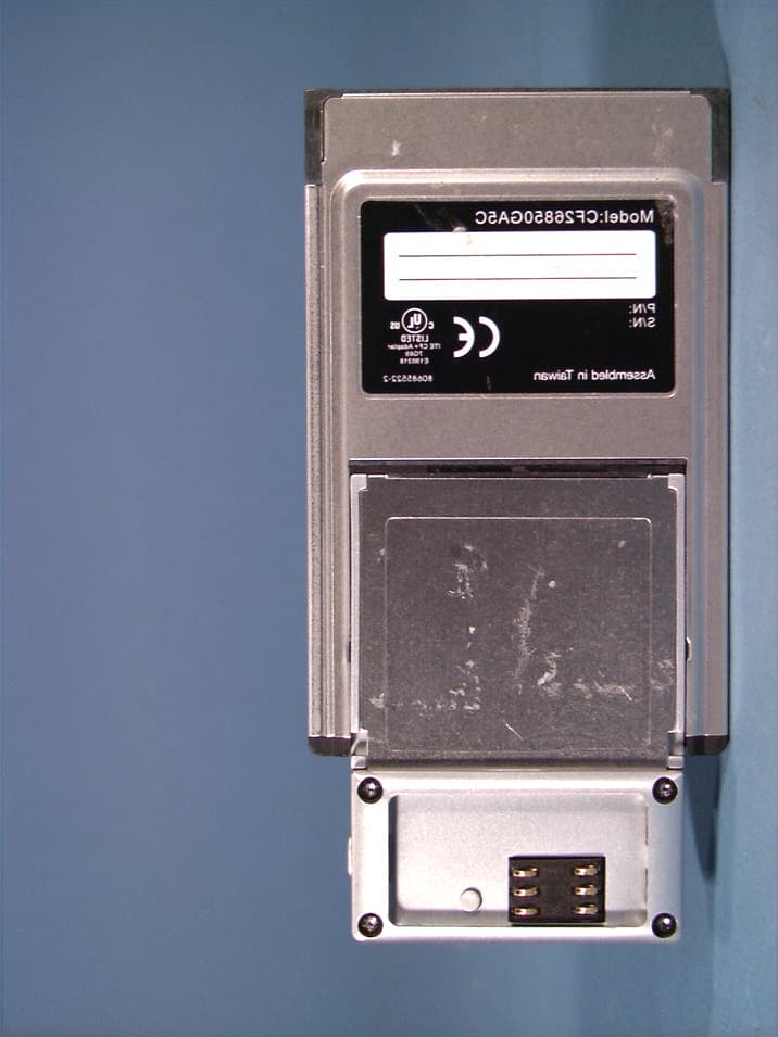
© 2002 PCTEST Lab PCS CDMA Modem Card CF Type II NVLAP Lab Code: 100431-0 FCC ID: PC6CF-2031 (Model(s): CF-2031, YM-2031U) © 2002 PCTEST Lab PCS CDMA Modem Card CF Type II NVLAP Lab Code: 100431-0 FCC ID: PC6CF-2031 (Model(s): CF-2031, YM-2031U) © 2002 PCTEST Lab PCS CDMA Modem Card CF Type II NVLAP Lab Code: 100431-0 FCC ID: PC6CF-2031 (Model(s): CF-2031, YM-2031U) © 2002 PCTEST Lab PCS CDMA Modem Card CF Type II NVLAP Lab Code: 100431-0 FCC ID: PC6CF-2031 (Model(s): CF-2031, YM-2031U) © 2002 PCTEST Lab PCS CDMA Modem Card CF Type II NVLAP Lab Code: 100431-0 FCC ID: PC6CF-2031 (Model(s): CF-2031, YM-2031U) © 2002 PCTEST Lab PCS CDMA Modem Card CF Type II NVLAP Lab Code: 100431-0 FCC ID: PC6CF-2031 (Model(s): CF-2031, YM-2031U) © 2002 PCTEST Lab PCS CDMA Modem Card CF Type II NVLAP Lab Code: 100431-0 FCC ID: PC6CF-2031 (Model(s): CF-2031, YM-2031U) © 2002 PCTEST Lab PCS CDMA Modem Card CF Type II NVLAP Lab Code: 100431-0 FCC ID: PC6CF-2031 (Model(s): CF-2031, YM-2031U) © 2002 PCTEST Lab PCS CDMA Modem Card CF Type II NVLAP Lab Code: 100431-0 FCC ID: PC6CF-2031 (Model(s): CF-2031, YM-2031U)
ID Label/Location Info
© 2002 PCTEST Lab FCC ID SAMPLE LABEL & LOCATION LABELLING REQUIREMENTS PER §§ 2.925 The Label shown shall be permanently affixed at a conspicuous location on the device and be readily visible to the user at the time of purchase. (SEE NEXT PAGE)
Internal Photos
© 2002 PCTEST Lab PCS CDMA Modem Card CF Type II NVLAP Lab Code: 100431-0 FCC ID: PC6CF-2031 (Model(s): CF-2031, YM-2031U) © 2002 PCTEST Lab PCS CDMA Modem Card CF Type II NVLAP Lab Code: 100431-0 FCC ID: PC6CF-2031 (Model(s): CF-2031, YM-2031U) © 2002 PCTEST Lab PCS CDMA Modem Card CF Type II NVLAP Lab Code: 100431-0 FCC ID: PC6CF-2031 (Model(s): CF-2031, YM-2031U) © 2002 PCTEST Lab PCS CDMA Modem Card CF Type II NVLAP Lab Code: 100431-0 FCC ID: PC6CF-2031 (Model(s): CF-2031, YM-2031U) © 2002 PCTEST Lab PCS CDMA Modem Card CF Type II NVLAP Lab Code: 100431-0 FCC ID: PC6CF-2031 (Model(s): CF-2031, YM-2031U) © 2002 PCTEST Lab PCS CDMA Modem Card CF Type II NVLAP Lab Code: 100431-0 FCC ID: PC6CF-2031 (Model(s): CF-2031, YM-2031U)
RF Exposure Info
YISO TELECOM FCC ID: PC6CF-2031 -- PCS CDMA Body SAR Generic Twin Phantom; Flat Section; Probe: ET3DV6 - SN1560 -- Probe Cal Date 20/02/01 Med. Parameters 1900 MHz Muscle: σ = 1.52 mho/m ε r = 53.3 ρ = 1.00 g/cm 3 ; Antenna Position -- In; Crest Factor 1.0 SAR (1g): 0.203 mW/g, SAR (10g): 0.104 mW/g YISO [PCS CDMA Only] CC Phone Model: CF-2031 / YM-2031U PCS CDMA Mode, Ch.0025 [1851.25MHz]; Flat Phantom; No BeltClip/No Holster Conducted Power = 23.4dBm; Spacing = 2.0cm from flat phantom to front (antenna side) of PDA & 2.5cm from flat phantom to EUT antenna Test Date -- 01/15/2002 SAR Tot [mW/g] 1.50E-3 4.50E-3 7.50E-3 1.05E-2 1.35E-2 PCTEST Engineering Laboratory, Inc. YISO TELECOM FCC ID: PC6CF-2031 -- PCS CDMA Body SAR Generic Twin Phantom; Flat Section; Probe: ET3DV6 - SN1560 -- Probe Cal Date 20/02/01 Med. Parameters 1900 MHz Muscle: σ = 1.52 mho/m ε r = 53.3 ρ = 1.00 g/cm 3 ; Antenna Position -- Out; Crest Factor 1.0 SAR (1g): 0.472 mW/g, SAR (10g): 0.276 mW/g YISO [PCS CDMA Only] CC Phone Model: CF-2031 / YM-2031U PCS CDMA Mode, Ch.0025 [1851.25MHz]; Flat Phantom; No BeltClip/No Holster Conducted Power = 23.4dBm; Spacing =2.0cm from flat phantom to front (antenna side) of PDA & 2.5cm from flat phantom to EUT antenna Test Date -- 01/15/2002 SAR Tot [mW/g] 3.37E-2 1.01E-1 1.69E-1 2.36E-1 3.03E-1 PCTEST Engineering Laboratory, Inc. YISO TELECOM FCC ID: PC6CF-2031 -- PCS CDMA Body SAR Generic Twin Phantom; Flat Section; Probe: ET3DV6 - SN1560 -- Probe Cal Date 20/02/01 Med. Parameters 1900 MHz Muscle: σ = 1.52 mho/m ε r = 53.3 ρ = 1.00 g/cm 3 ; Antenna Position -- In; Crest Factor 1.0 SAR (1g): 0.201 mW/g, SAR (10g): 0.0792 mW/g YISO [PCS CDMA Only] CC Phone Model: CF-2031 / YM-2031U PCS CDMA Mode, Ch.0600 [1880.00MHz]; Flat Phantom; No BeltClip/No Holster Conducted Power = 23.4dBm; Spacing = 2.0cm from flat phantom to front (antenna side) of PDA & 2.5cm from flat phantom to EUT antenna Test Date -- 01/15/2002 SAR Tot [mW/g] 1.40E-3 4.20E-3 7.00E-3 9.80E-3 1.26E-2 PCTEST Engineering Laboratory, Inc. YISO TELECOM FCC ID: PC6CF-2031 -- PCS CDMA Body SAR Generic Twin Phantom; Flat Section; Probe: ET3DV6 - SN1560 -- Probe Cal Date 20/02/01 Med. Parameters 1900 MHz Muscle: σ = 1.52 mho/m ε r = 53.3 ρ = 1.00 g/cm 3 ; Antenna Position -- Out; Crest Factor 1.0 SAR (1g): 0.615 mW/g, SAR (10g): 0.355 mW/g YISO [PCS CDMA Only] CC Phone Model: CF-2031 / YM-2031U PCS CDMA Mode, Ch.0600 [1880.00MHz]; Flat Phantom; No BeltClip/No Holster Conducted Power = 23.4dBm; Spacing = 2.0cm from flat phantom to front (antenna side) of PDA & 2.5cm from flat phantom to EUT antenna Test Date -- 01/15/2002 SAR Tot [mW/g] 4.80E-2 1.44E-1 2.40E-1 3.36E-1 4.32E-1 PCTEST Engineering Laboratory, Inc. YISO TELECOM FCC ID: PC6CF-2031 -- PCS CDMA Body SAR Generic Twin Phantom; Flat Section; Probe: ET3DV6 - SN1560 -- Probe Cal Date 20/02/01 Med. Parameters 1900 MHz Muscle: σ = 1.52 mho/m ε r = 53.3 ρ = 1.00 g/cm 3 ; Antenna Position -- In; Crest Factor 1.0 SAR (1g): 0.197 mW/g, SAR (10g): 0.103 mW/g YISO [PCS CDMA Only] CC Phone Model: CF-2031 / YM-2031U PCS CDMA Mode, Ch.1175 [1908.75MHz]; Flat Phantom; No BeltClip/No Holster Conducted Power = 23.4dBm; Spacing = 2.0cm from flat phantom to front (antenna side) of PDA & 2.5cm from flat phantom to EUT antenna Test Date -- 01/15/2002 SAR Tot [mW/g] 1.90E-3 5.70E-3 9.50E-3 1.33E-2 1.71E-2 PCTEST Engineering Laboratory, Inc. YISO TELECOM FCC ID: PC6CF-2031 -- PCS CDMA Body SAR Generic Twin Phantom; Flat Section; Probe: ET3DV6 - SN1560 -- Probe Cal Date 20/02/01 Med. Parameters 1900 MHz Muscle: σ = 1.52 mho/m ε r = 53.3 ρ = 1.00 g/cm 3 ; Antenna Position -- Out; Crest Factor 1.0 SAR (1g): 0.438 mW/g, SAR (10g): 0.256 mW/g YISO [PCS CDMA Only] CC Phone Model: CF-2031 / YM-2031U PCS CDMA Mode, Ch.1175 [1908.75MHz]; Flat Phantom; No BeltClip/No Holster Conducted Power = 23.4dBm; Spacing = 2.0cm from flat phantom to front (antenna side) of PDA & 2.5cm from flat phantom to EUT antenna Test Date -- 01/15/2002 SAR Tot [mW/g] 3.65E-2 1.10E-1 1.83E-1 2.55E-1 3.29E-1 PCTEST Engineering Laboratory, Inc. YISO TELECOM FCC ID: PC6CF-2031 -- PCS CDMA Hand SAR Generic Twin Phantom; Flat Section; Probe: ET3DV6 - SN1560 -- Probe Cal Date 20/02/01 Med. Parameters 1900 MHz Muscle: σ = 1.52 mho/m ε r = 53.3 ρ = 1.00 g/cm 3 ; Antenna Position -- In; Crest Factor 1.0 SAR (1g): 0.203 mW/g, SAR (10g): 0.109 mW/g YISO [PCS CDMA Only] CC Phone Model: CF-2031 / YM-2031U PCS CDMA Mode, Ch.0025 [1851.25MHz]; Flat Phantom; No BeltClip/No Holster Conducted Power = 23.4dBm; Spacing = Flat phantom touching back of EUT, w/ EUT antenna = 1.0cm from flat phantom Test Date -- 01/15/2002 SAR Tot [mW/g] 6.80E-3 2.04E-2 3.40E-2 4.76E-2 6.12E-2 PCTEST Engineering Laboratory, Inc. YISO TELECOM FCC ID: PC6CF-2031 -- PCS CDMA Hand SAR Generic Twin Phantom; Flat Section; Probe: ET3DV6 - SN1560 -- Probe Cal Date 20/02/01 Med. Parameters 1900 MHz Muscle: σ = 1.52 mho/m ε r = 53.3 ρ = 1.00 g/cm 3 ; Antenna Position -- Out; Crest Factor 1.0 SAR (1g): 1.80 mW/g, SAR (10g): 0.969 mW/g YISO [PCS CDMA Only] CC Phone Model: CF-2031 / YM-2031U PCS CDMA Mode, Ch.0025 [1851.25MHz]; Flat Phantom; No BeltClip/No Holster Conducted Power = 23.4dBm; Spacing = Flat phantom touching back of EUT, w/ EUT antenna = 1.0cm from flat phantom Test Date -- 01/15/2002 SAR Tot [mW/g] 1.06E-1 3.18E-1 5.30E-1 7.42E-1 9.54E-1 PCTEST Engineering Laboratory, Inc. YISO TELECOM FCC ID: PC6CF-2031 -- PCS CDMA Hand SAR Generic Twin Phantom; Flat Section; Probe: ET3DV6 - SN1560 -- Probe Cal Date 20/02/01 Med. Parameters 1900 MHz Muscle: σ = 1.52 mho/m ε r = 53.3 ρ = 1.00 g/cm 3 ; Antenna Position -- In; Crest Factor 1.0 SAR (1g): 0.201 mW/g, SAR (10g): 0.110 mW/g YISO [PCS CDMA Only] CC Phone Model: CF-2031 / YM-2031U PCS CDMA Mode, Ch.0600 [1880.00MHz]; Flat Phantom; No BeltClip/No Holster Conducted Power = 23.4dBm; Spacing = Flat phantom touching back of EUT, w/ EUT antenna = 1.0cm from flat phantom Test Date -- 01/15/2002 SAR Tot [mW/g] 9.50E-3 2.85E-2 4.75E-…
Text truncated - open the document above for the full version.
RF Exposure Info
© 2002 PCTEST Engineering Lab., Inc. PCTEST Engineering Laboratory, Inc. 6660-B Dobbin Road • Columbia, MD 21045 • U.S.A. TEL (410) 290-6652 • FAX (410) 290-6654 http://www.pctestlab.com CERTIFICATE OF COMPLIANCE (SAR EVALUATION) YISO TELECOM CO., LTD. Dates of Tests: January 15, 2002 261 Yangjae-dog, Seocho-ku, Test Report S/N: SAR.220115733.PC6 Seoul, KOREA 137-894 Test Site: PCTEST Lab, Columbia MD Attn: Mr. Sung Hyun Lee, Wireless Comm. Lab Manager/R&D FCC ID PC6CF-2031 APPLICANT YISO TELECOM CO., LTD. EUT Type: PCS CDMA Radio Card (PCMCIA) Tx Frequency: 1851.25 — 1908.75 MHz (PCS CDMA) Rx Frequency: 1931.25 — 1988.75 MHz (PCS CDMA) Max. RF Output Power: 0.473 W EIRP PCS CDMA (26.751 dBm) Max. SAR Measurement: 0.615mW/g PCS Body SAR; 1.140mW/g PCS Hand SAR Trade Name/Model(s): CC PHONE / CF-2031, YM-2031U FCC Classification: Licensed Portable Transmitter Worn on Body (PCT) FCC Rule Part(s): §2.1093; FCC/OET Bulletin Supplement C [July 2001] Application Type: Certification This wireless portable device has been shown to be capable of continued compliance for localized specific absorption rate (SAR) for uncontrolled environment/general population exposure limits specified in ANSI/IEEE Std. C95.1-1992 and had been tested in accordance with the measurement procedures specified in ANSI/IEEE Std. C95.3-1992 and IEEE Std. 1528 (Draft Aug.2000). I attest to the accuracy of data. All measurements reported herein were performed by me or were made under my supervision and are correct to the best of my knowledge and belief. I assume full responsibility for the completeness of these measurements and vouch for the qualifications of all persons taking them. NVLAP accreditation does not constitute any product endorsement by NVLAP or any agency of the United States Government. PCTEST certifies that no party to this application has been denied the FCC benefits pursuant to Section 5301 of the Anti-Drug Abuse Act of 1988, 21 U.S.C. 862. 220115733.PC6 SAR Measurement Report FCC Part 24 Certification © 2002 PCTEST Lab i Table of Contents 1.1 SCOPE 1 2.1 INTRODUCTION / SAR DEFINITION 2 3.1 SAR MEASUREMENT SET-UP 3 4.1 E-FIELD PROBE SYSTEM 4 5.1 E-FIELD PROBE CALIBRATION PROCESS 5-6 6.1 PHANTOM, HOLDER, & EQUIVALENT TISSUE 7 7.1 SYSTEM SPECIFICATIONS 8 8.1 MEASUREMENT PROCESS 9 9.1 HEAD SAR TEST POSITIONS OF THE PHONE 10 10.1 BODY SAR TEST SETUP 11 11.1 ANSI/IEEE C95.1 RF EXPOSURE LIMITS 12 12.1 MEASUREMENT UNCERTAINTIES 13 13.1 TEST DATA SUMMARY 14-15 14.1 SAR TEST EQUIPMENT LIST 16 15.1 CONCLUSION 17 16.1 REFERENCES 18 Test Report S/N: SAR.220115733.PC6 SAR Measurement Report Test Date(s): January 15, 2002 FCC Part 24 Certification © 2002 PCTEST Lab PCS CDMA Radio Card (PCMCIA) 1 FCC ID: PC6CF-2031 (Model(s): CF-2031, YM-2031U) SAR MEASUREMENT REPORT 1.1 Scope Environmental evaluation measurements of specific absorption rate 1 (SAR) distributions in simulated human head and body tissues exposed to radiofrequency (RF) radiation from wireless portable devices for compliance with the rules and regulations of the U.S. Federal Communications Commission (FCC). 2 Company Name: YISO TELECOM CO., LTD. Address: 261 Yangjae-dog, Seocho-ku, Seoul, KOREA 137-894 Attention: Mr. Sung Hyun Lee, Wireless Comm. Lab Manager/R&D • EUT Type: PCS CDMA Radio Card (PCMCIA) • Trade Name / Model(s): CC PHONE / CF-2031, YM-2031U • FCC IDENTIFIER: PC6CF-2031 • Tx Frequency: 1851.25 — 1908.75 MHz (PCS CDMA) • Rx Frequency: 1931.25 — 1988.75 MHz (PCS CDMA) • FCC Classification: Licensed Portable Transmitter Worn on Body (PCT) • Modulation(s): CDMA • FCC Rule Part(s): §2.1093, OET Bulletin 65, Supplement C (July 2001) • Max. RF Output Power: 0.473 W EIRP PCS CDMA (26.751 dBm) • Max SAR Measurement: 0.615mW/g PCS Body SAR; 1.140mW/g PCS Hand SAR • Application Type: Certification • Dates of Tests: January 15, 2002 Place of Tests: PCTEST Engineering Lab. Columbia, MD, U.S.A. • Report Serial No.: SAR.220115733.PC6 1 Specific Absorption Rate (SAR) is a measure of the rate of energy absorption due to exposure to an RF transmitting source (wireless portable device). 2 IEEE/ANSI Std. C95.1-1992 limits are used to determine compliance with FCC ET Docket 93-62. Fig. 1 SAR Test Setup Test Report S/N: SAR.220115733.PC6 SAR Measurement Report Test Date(s): January 15, 2002 FCC Part 24 Certification © 2002 PCTEST Lab PCS CDMA Radio Card (PCMCIA) 2 FCC ID: PC6CF-2031 (Model(s): CF-2031, YM-2031U) 2.1 INTRODUCTION The FCC has adopted the guidelines for evaluating the environmental effects of radiofrequency radiation in ET Docket 93-62 on Aug. 6, 1996 to protect the public and workers from the potential hazards of RF emissions due to FCC-regulated portable devices.[1] The safety limits used for the environmental evaluation measurements are based on the criteria published by the American National Standards Institute (ANSI) for localized specific absorption rate (SAR) in IEEE/ANSI C95.1-1992 Standard for Safety Levels with Respect to Human Exposure to Radio Frequency Electromagnetic Fields, 3 kHz to 300 GHz. (c) 1992 by the Institute of Electrical and Electronics Engineers, Inc., New York, New York 10017.[2] The measurement procedure described in IEEE/ANSI C95.3-1992 Recommended Practice for the Measurement of Potentially Hazardous Electromagnetic Fields - RF and Microwave[3] is used for guidance in measuring SAR due to the RF radiation exposure from the Equipment Under Test (EUT). These criteria for SAR evaluation are similar to those recommended by the National Council on Radiation Protection and Measurements (NCRP) in Biological Effects and Exposure Criteria for Radiofrequency Electromagnetic Fields,” NCRP Report No. 86 (c) NCRP, 1986, Bethesda, MD 20814.[5] SAR is a measure of the rate of energy absorption due to exposure to an RF transmitting source. SAR values have been related to threshold levels for potential biological hazards. 2.2 SAR Definition Specific Absorption Rate (SAR) is defined as the time derivative (rate) of the incremental energy (d…
Text truncated - open the document above for the full version.
RF Exposure Info
© 2002 PCTEST Lab PCS CDMA Modem Card CF Type II NVLAP Lab Code: 100431-0 FCC ID: PC6CF-2031 (Model(s): CF-2031, YM-2031U) © 2002 PCTEST Lab PCS CDMA Modem Card CF Type II NVLAP Lab Code: 100431-0 FCC ID: PC6CF-2031 (Model(s): CF-2031, YM-2031U) © 2002 PCTEST Lab PCS CDMA Modem Card CF Type II NVLAP Lab Code: 100431-0 FCC ID: PC6CF-2031 (Model(s): CF-2031, YM-2031U) © 2002 PCTEST Lab PCS CDMA Modem Card CF Type II NVLAP Lab Code: 100431-0 FCC ID: PC6CF-2031 (Model(s): CF-2031, YM-2031U)
RF Exposure Info
Probe ET3DV6 SN:1560 Manufactured:December 1, 2000 Calibrated:February 20, 2001 Calibrated for System DASY3 Page 1 of 8 ET3DV6 SN:1560 DASY3 - Parameters of Probe: ET3DV6 SN:1560 Sensitivity in Free SpaceDiode Compression NormX1.48 μV/(V/m) 2 DCP X98mV NormY1.51 μV/(V/m) 2 DCP Y98mV NormZ1.43 μV/(V/m) 2 DCP Z98mV Sensitivity in Tissue Simulating Liquid Head450MHz ε r =43.5 ± 5% σ = 0.87 ± 10% mho/m ConvF X7.17 extrapolatedBoundary effect: ConvF Y7.17 extrapolatedAlpha0.25 ConvF Z7.17 extrapolatedDepth3.21 Head900MHz ε r =42 ± 5% σ = 0.97 ± 10% mho/m ConvF X6.59 ± 7% (k=2)Boundary effect: ConvF Y6.59 ± 7% (k=2)Alpha0.32 ConvF Z6.59 ± 7% (k=2)Depth2.93 Head1500MHz ε r =40.4 ± 5% σ = 1.23 ± 10% mho/m ConvF X5.82 interpolatedBoundary effect: ConvF Y5.82 interpolatedAlpha0.41 ConvF Z5.82 interpolatedDepth2.55 Head1800MHz ε r =40 ± 5% σ = 1.40 ± 10% mho/m ConvF X5.43 ± 7% (k=2)Boundary effect: ConvF Y5.43 ± 7% (k=2)Alpha0.46 ConvF Z5.43 ± 7% (k=2)Depth2.36 Sensor Offset Probe Tip to Sensor Center2.7mm Optical Surface Detection2.0 ± 0.2mm Page 2 of 8 ET3DV6 SN:1560 Receiving Pattern (φ), θ = 0° f = 30 MHz, TEM cell ifi110 0 10 20 30 40 50 60 70 80 90 100 110 120 130 140 150 160 170 180 190 200 210 220 230 240 250 260 270 280 290 300 310 320 330 340 350 XYZTot f = 100 MHz, TEM cell ifi110 0 10 20 30 40 50 60 70 80 90 100 110 120 130 140 150 160 170 180 190 200 210 220 230 240 250 260 270 280 290 300 310 320 330 340 350 XYZTot f = 300 MHz, TEM cell ifi110 0 10 20 30 40 50 60 70 80 90 100 110 120 130 140 150 160 170 180 190 200 210 220 230 240 250 260 270 280 290 300 310 320 330 340 350 XYZTot f = 900 MHz, TEM cell ifi110 0 10 20 30 40 50 60 70 80 90 100 110 120 130 140 150 160 170 180 190 200 210 220 230 240 250 260 270 280 290 300 310 320 330 340 350 XYZTot Page 3 of 8 ET3DV6 SN:1560 Isotropy Error (φ), θ = 0° -1.00 -0.80 -0.60 -0.40 -0.20 0.00 0.20 0.40 0.60 0.80 1.00 060120180240300360 error[dB] 30 MHz 100 MHz 300 MHz 900 MHz 1800 MHz 2500 MHz f = 1800 MHz, WG R22 0 10 20 30 40 50 60 70 80 90 100 110 120 130 140 150 160 170 180 190 200 210 220 230 240 250 260 270 280 290 300 310 320 330 340 350 XYZTot f = 2500 MHz, WG R26 0 10 20 30 40 50 60 70 80 90 100 110 120 130 140 150 160 170 180 190 200 210 220 230 240 250 260 270 280 290 300 310 320 330 340 350 XYZTot Page 4 of 8 ET3DV6 SN:1560 Frequency Response of E-Field ( TEM-Cell:ifi110, Waveguide R22) 0.50 0.60 0.70 0.80 0.90 1.00 1.10 1.20 1.30 1.40 1.50 050010001500200025003000 f [MHz] frequency response TEMR22 Page 5 of 8 ET3DV6 SN:1560 Dynamic Range f(SAR brain ) ( TEM-Cell:ifi110 ) ET3DV6 SN:1560 1.E+0 1.E+1 1.E+2 1.E+3 1.E+4 1.E+5 1.E+6 1.E+7 0.00010.0010.010.11.10.100. mW/cm 3 μ V not compensatedcompensated -2.0 -1.0 0.0 1.0 0.0010.010.1110100 mW/cm 3 errror[dB] Page 6 of 8 Conversion Factor Assessment Head900MHz ε r =42 ± 5% σ = 0.97 ± 10% mho/m ConvF X6.59 ± 7% (k=2)Boundary effect: ConvF Y6.59 ± 7% (k=2)Alpha0.32 ConvF Z6.59 ± 7% (k=2)Depth2.93 Head1800MHz ε r =40 ± 5% σ = 1.40 ± 10% mho/m ConvF X5.43 ± 7% (k=2)Boundary effect: ConvF Y5.43 ± 7% (k=2)Alpha0.46 ConvF Z5.43 ± 7% (k=2)Depth2.36 ET3DV6 SN:1560 f = 900 MHz, WG R9 (head) 0.00 0.10 0.20 0.30 0.40 0.50 0.60 0.70 0.80 0.90 0204060 z[mm] SAR[mW/cm 3 ] / W AnalyticalMeasuremets f = 1800 MHz, WG R22 (head) 0.00 1.00 2.00 3.00 4.00 5.00 6.00 7.00 0204060 z[mm] SAR[mW/cm 3 ] / W AnalyticalMeasuremets Page 7 of 8 Deviation from Isotropy in HSL Error (θ,φ), f = 900 MHz 0 40 80 120 160 200 240 280 320 0 10 20 30 40 50 60 -1.00 -0.80 -0.60 -0.40 -0.20 0.00 0.20 0.40 0.60 0.80 1.00 Error [dB] θ φ -1.00--0.80-0.80--0.60-0.60--0.40-0.40--0.20-0.20-0.00 0.00-0.200.20-0.400.40-0.600.60-0.800.80-1.00 Page 8 of 8
RF Exposure Info
1900MHz Muscle Dipole Validation Generic Twin Phantom; Flat Section; Probe: ET3DV6 - SN1560 -- Probe Cal Date 20/02/01 Med. Parameters 1900 MHz Muscle: σ = 1.52 mho/m ε r = 53.3 ρ = 1.00 g/cm 3 ; Antenna Position -- Out; Crest Factor 1.0 SAR (1g): 8.37 mW/g, SAR (10g): 4.32 mW/g 1900MHz Muscle Dipole Validation (D1900V2 S/N: 502) Frequency: 1900 MHz; Antenna Input Power: 250 [mW] PCTEST Muscle Tissue Simulating Liquid [01/15/2002] SAR Tot [mW/g] 8.18E-1 2.45E+0 4.09E+0 5.72E+0 7.36E+0 PCTEST Engineering Laboratory, Inc.
RF Exposure Info
© 2002 PCTEST Lab PCS CDMA Modem Card CF Type II NVLAP Lab Code: 100431-0 FCC ID: PC6CF-2031 (Model(s): CF-2031, YM-2031U) © 2002 PCTEST Lab PCS CDMA Modem Card CF Type II NVLAP Lab Code: 100431-0 FCC ID: PC6CF-2031 (Model(s): CF-2031, YM-2031U) © 2002 PCTEST Lab PCS CDMA Modem Card CF Type II NVLAP Lab Code: 100431-0 FCC ID: PC6CF-203…
Text truncated - open the document above for the full version.
Contact Information
Applicant
Sung H Lee(Senior Engineer)
Technical Contact
PCTEST Engineering Laboratory Inc.Randy Ortanez
[email protected]410-290-6652
6660-B Dobbin Road · Columbia, Maryland · United States
Non-Technical Contact
PCTEST Engineering Laboratory Inc.Randy Ortanez
[email protected]410-290-6652
Test Firm
PCTEST Engineering Laboratory, Inc.Randy Ortanez
Technical Specifications
| # | Rule Parts | Frequency Range | Power Output | Emission | Tolerance |
|---|---|---|---|---|---|
| 1 | 24E | 1.85 GHz - 1.91 GHz | 473.00 mW | 1M25F9W | 2.5000000000 ppm |
Other Applications from Growell Telecom Co., Ltd.
PC6CF2031
Jul 23, 2002PCS CDMA Modem Card CF Type II
Equipment Class
PCT - PCS Licensed Transmitter worn on body
PC6EK-001B
Feb 13, 2002CDMA Cellular Modem
Equipment Class
TNB - Licensed Non-Broadcast Station Transmitter
PC6YM-1031K
Dec 27, 2001CDMA Wireless Modem PC Card (PCMCIA)
Equipment Class
TNB - Licensed Non-Broadcast Station Transmitter
PC6YM-4010K
Dec 26, 2001CDMA Wireless Modem PC Card (PCMCIA)
Equipment Class
TNB - Licensed Non-Broadcast Station Transmitter
PC6YFW-0001
Jan 29, 2001Single-Mode Cellular CDMA Card
Equipment Class
TNB - Licensed Non-Broadcast Station Transmitter