PCMDFM-100FM Transmitter
Hyun Won Inc.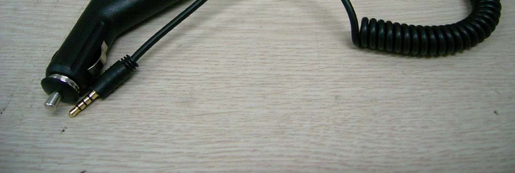
Click to zoom
Application Details
- Equipment Class
- DXX - Part 15 Low Power Communication Device Transmitter
- Date of Grant
- Jul 31, 2006
- Application Purpose
- Original Equipment
- Date of Application
- Jul 31, 2006
- Equipment Note
- FM Transmitter
- Frequency Range
- 88.30000000 - 88.90000000
- Company
- Hyun Won Inc.
- Country
- South Korea
Documents & Files
Document Text
Text extracted from the exhibit documents filed with the FCC. Open a document above to read the original.
Users Manual
1. Introduction DFM-100 Wireless music adapter lets you listen to any portable music device over any FM tuner and speaker setup, without clumsy or constricting cable hookup. It's the perfect way to simply and effciently listen to MP3s, CDsm and mini-discs in the comfort. 2. Operation 1) Connect FM transmitter audio jack into earphone jack of MP3 player. 2) Play MP3P and on Power switch. Charging(red),Complet(off),Strangeness(green) Power 3) Select FM frequency. 88.3(red), 88.7(green), 88.9(red+green) Select Switch 4) Set FM audio frequency to the selected FM frequency in step 3 before. 5) Adjust the volume of your audio device and FM radio and Enjoy the wireless music. 3. Specification Frequency Range : 88.9/88.7/88.3 MHz Modulation : FM Frequency Type : F3E Battery(Bulit-in) : Li-Polymer Max. Running Time : 6 hr Operating Temp : -10 ~ 71°C Size(WxHxD) : 25x25x25 mm Weight : 15g Accessor y Car Charging Cable 4. Safety Instruction 1) Avoide humidity and dust. 2) Do not store in car for many hours in winter or summer. 3) Do not let any foreign matter spill into the device. 4) Do not expose to direct sunlight or heat sources. 5) Do not expose to chemicals such as benzene and thinners. 6) Do not try to disassemble and repair the device yourself. 7) Do not drop the unit. 8) Do not touch with wet hands. 9) Do not use the unit in restricted place like airport or hospital using sensitive device. 10) Do not use while driving a car. Built-in Battery 1) Do not use a damaged built-in or DC adaptor. 2) Exceeding the recommended recharging time may cause a fire. 3) Fully recharge the battery before initial use or after a lengthy period of inactivity. 4) When the battery no longer holds its charge despite being fully recharged; it's time to replace it. 5. Warranty Hyun Won Inc. warrants this products as free of defects in material, design and workmanship for a period of six(6) months from the original date of purchase. CAUTION This Limited Warranty will be honored only within the geographical location that DFM-100 purchased. Hyun Won Inc. will repair or replace DFM-100 if they fail to function properly during the warranty period, subject to any conditions and/ or limitations stated herein. Such repair service will include all labor as well as any necessary adjustments and/ or replacement parts. Such repair or replacement is the sole remedy under this warranty. Warranty Conditions 1) Request for Warranty Service will not be accepted without proof of date of purchase, such as a copy of the original dated DFM-100 sales receipt. 2) This Warranty does not apply to the battery used in DFM-100. 3) This Warranty does not cover circumatances beyound Hyun Won Inc's control, not problems caused by failure to follow the operating instructions in the DFM-100 User's Guides 4) This Warranty does not apply when failure is due to shipping damage, accident, alteration, modification, unauthorized service, misuse, abuse, use with incompatible accessories or attachments, failure to follow Hyun Won Inc's operation, maintenance or repacking instruction, failure to use items supplied by Hyun Won Inc.(Such as adapters and cables), or claims made after the duration of this Warranty. 5) This Warranty does not apply when repairs performed by non-authorized service centers such as opening of the product by a non-authorized person. FCC Statement This device complies with parts 15 of the FCC Rules. Operation is subject to the following two conditions;(1)This device may not cause harmful interference, and (2)this device must accept any interference received, including interference that many cause undesired operation. Caution : Any changes or modifications in construction of this device which are not expressly approved by the party responsible for compliance could void the user's authority to operate the equipment. Note : This equipment has been tested and found to comply with the limits for a Class B digital device, pursuant to part 15 of the FCC Rules. These limits are designed to provide reasonable protection against harmful interference in a residential installation. This equipment generates, uses and can radiate radio frequency energy and, if not installed and used in accordance with the instructions, may cause harmful interference to radio communications, However, there is no guarantee that interference will not occur in a particular installation. If the equipment does cause harmful interference to radio or television reception, which can be determined by turning the equipment off and on, the user is encouraged to try to correct the interference by one or more of the following measures; - Reorient or relocate the receiving antenna. - Increase the separation between the equipment and receiver. - Connect the equipment into an outlet on a circuit different from that to which the receiver is connected - Consult the dealer or an experienced radio/TV technician for help.
Block Diagram
BH1417F RF-AMP 5V X-TAL 7.6MHz ROHM Audio input L R VCO BATTERY(LITHIUMPOLYMER) ISL6292( ) Block Diagram( DFM-100)
Cover Letter(s)
4th Floor, e-Venture Building, 74-2, Shincheon 3-dong, Dong-gu, Deagu-City, South Korea Tel : 82.53.743.7200 / Fax : 82.53.743.2112 www.mobiblu.com Factory : 333-1 Shindea-Ri, Kumho-Eup, YoungCheon-City, Kyoungbuk, South Korea http://www.mobiBLU.com e-mail : [email protected] May 22, 2006 Compliance Certification Services Certification Division 561F Monterey Road Morgan Hill, CA 95037 To whom it may concern: We, the undersigned, hereby authorize IST Co., Ltd., to act on our behalf in all manners relating to application for equipment authorization, including signing of all documents relating to these matters. Any and all acts carried out by IST Co., Ltd. on our behalf shall have the same effect as acts of our own. We, the undersigned, hereby certify that we are not subject to a denial of federal benefits, that includes FCC benefits, pursuant to Section 5301 of the Anti-Drug Abuse Act of 1988, 21 U.S.C. 853(a). In authorizing IST Co., Ltd. as our agent, we still recognize that we are responsible to: a) comply with the relevant provisions of the certification program; b) make all necessary arrangements for the conduct of the evaluation, including provision for examining documentation and access to all areas, records (including internal audit reports) and personnel for the purposes of evaluation (e.g. testing, inspection, assessment, surveillance, reassessment) and resolution of complaints; c) make claims regarding certification only in respect of the scope for which certification has been granted; d) do not use our product certification in such a manner as to bring the Certification Division into disrepute and not make any statement regarding our product certification which the Certification Division may consider misleading or unauthorized; 4th Floor, e-Venture Building, 74-2, Shincheon 3-dong, Dong-gu, Deagu-City, South Korea Tel : 82.53.743.7200 / Fax : 82.53.743.2112 www.mobiblu.com Factory : 333-1 Shindea-Ri, Kumho-Eup, YoungCheon-City, Kyoungbuk, South Korea http://www.mobiBLU.com e-mail : [email protected] e) upon suspension or cancellation of certification, discontinue use of all advertising matter that contains any reference thereto and return any certification documents as required by the Certification Division; f) use certification only to indicate the products are certified as being in conformity with specified standards; g) endeavor to ensure that no certificate or report nor any part thereof is used in a misleading manner; h) ensure that any reference to our product certification in communication media such as documents, brochures or advertising, complies with the requirements of the Certification Division; i) keep a record of all complaints made known to the us relating to the product’s compliance with requirements of the relevant standard and to make these records available to the Certification Division when requested; j) take appropriate action with respect to such complaints and any deficiencies found in products or services that affect compliance with the requirements for certification; k) document the actions taken. This authorization is valid until further written notice from the applicant. Sincerely Yours, Yo n g S e o g K o / D i r e c t o r GQM(Global Quality Management) Dept. Hyun Won Inc.
Cover Letter(s)
1 Helen Zhao Subject: FW: Hyun Won Inc., FCC ID: PCMPCMDFM-100, Assessment NO.: AN06T5943, Notice#1 DFM-100_Operatio nal Descriptio... DFM-100_External photos.pdf DFM-100_Internal Photos.pdf DFM-100_Setup photos.pdf DFM-100_ID Label.pdf DFM-100_TstRpt.p df From: sgkim Sent: Tuesday, Aug 1, 2006 5:29 PM To: Helen Zhao Subject: RE: Hyun Won Inc., FCC ID: PCMPCMDFM-100, Assessment NO.: AN06T5943, Notice#1 Dear Helen, A1. Please chech the attached documents. A2. The test report was modified. A3. Thanks for your guide. Best regards, S.G.Kim / Asst.Manager IST EMC Laboratory -----Original Message----- Sent: Wednesday, July 12, 2006 6:05 PM Subject: Hyun Won Inc., FCC ID: PCMPCMDFM-100, Assessment NO.: AN06T5943, Notice#1 Question #1: Please submit the following documents: External photos Internal Photos Setup photos FCC ID label format Operational Description Request for confidentiality Letter Question #2: Please check whether Bandwidth was tested with maximum input signal and user controls adjusted to maximize emission (MP3 player in your case). If so, please indicate clearly in the test report. Question #3: For your information, please select Equipment Class - DXX Part 15 Low power communication transmitter on Form 731. Best Regards, Helen Zhao The items indicated above must be submitted before processing can continue on the above referenced application. Failure to provide the requested information within 30 days of the original e-mail date may result in application dismissal and forfeiture of the filing fee. Also, please note that partial responses increase processing time and should 2 not be submitted. Any questions about the content of this correspondence should be directed to the e-mail address listed below the name of the sender.
ID Label/Location Info
ID Label/Location Information FM Transmitter FCC ID : PCMDFM-100 MADE IN KOREA
Operational Description
Operational Description The BH1417F is a FM stereo transmitter IC that transmits simple configuration. The IC consists of a stereo modulator for generating stereo composite signals and a FM transmitter for broadcasting a FM signal on the air. The stereo modulator generates a composite signal which consists of the MAIN, SUB, and pilot signal from a 38 kHz oscillator. The FM transmitter radiates FM wave on the air by modulating the carrier signal with a composite signal. Frequency is set for North America. Applications Wireless speakers, MP3 player, Car TV, Car navigation Features 1) It is possible to improve the timbre because it has the pre-emphasis circuit, limiter circuit, and the low-pass filter circuit. 2) Built-in pilot-tone system FM stereo modulator circuit. 3) The transmission frequency is stable because it has a PLL system FM transmitter circuit. 4) PLL controls data input in parallel (4bits, 14ch for North America)
Schematics
L11 2.2uHL12 2.2uHL10 330nH R4101 VCC-1 VCC-1 + TC1 10uF/ 6.3V VCC-1 PWR C20 104 R633K R18100 PWR + TC3 47uF/6.3V Q2 THN6301S R25471 R28562 R30 100K R29562 J2CON5 12345 R13683 VCC_1 LED_R LED_G C9 101 R31 103 RF_OUT VCC-2 2 13 Y17.6M 1 3 C11 331 R9 10K L1568nH C145.6P SPK_R C1382pF C1533pF R113.3KR103.3KR7821 R3 10 Q1 KTC3880Y R1 10 R2101 R8120K R12 10K C12222 R203K 54321 VCC-2 A5A4A3A2 L17 82nH A1 RF_OUT A3 R32562 R33562 PA0 SW1 주파수 SW2 전원 PB1PB0 A2 A4 3 Q4 2SC5343SY 1 R143.3K R24 22K Q3 2SA1980SY R5 22K 5 VCC-1 VCC-2 4 U2 ISL6292 VBAT 12 V_IN 1 IREF 9 1MIN 10 V2P 8 TIME 4 STATUS 3 GND 5 FAULT 2 11 11 7 7 2 J1CON2 56 C17153 C18104 LED1B LED 32 LED1A LED 41 LED2B LED 32 LED2A LED 41 A5 A1 R21 100K L18 330nH R23 75K R22 100K PB1PB0 L19 330nH U3 HT48RA0-2_20ASSOP PB5 11 PB4 12 PA3 19 PA2 20 PA1 1 PA0 2 PB3 13 PB2 14 PB1 3 PB0 4 vss 9 PC0/REM 5 RES 10 VDD 6 OSC1 8 OSC2 7 PA7 15 PA6 16 PA5 17 PA4 18 PA0 PLL1PLL2PLL3PLL4 LED_RLED_G C19 104 B3PAD 1 B4PAD 1 B5PAD 1 R15 100K PAD 로수정 R16 100K R17 100K R19 100K PLL4PLL3PLL2PLL1 J3CON5 12345 R26 514R27 514 B1PAD 1 B2PAD 1 + TC5 10uF/ 6.3V C21 104 U1BH1417FV D0 17 D3 20 PHASE_ADJ 21 D2 19 D1 18 GND 6 L_CH__IN 24 R_CH_IN 1 FILTER 4 MPXL_OUT 5 PLL_DEF_OUT 7 RF_OSC 10 RF_GND 11 NC2 16 NC1 9 RF_OUT 12 X_OUT 14 X_IN 15 VCC 8 PLL_VCC 13 LPF_1 3 PRE_EMPHASIS2 23 PRE_EMPHASIS1 2 LPF_2 22 C6103 C16 102 SPK_L C727 C827 C24105 C10105 C25105 D1 KDV1472C C4 392 C1 392 C5 151 R36472 C2 151 VCC-2
Test Report
IST Co., Ltd EMC LABORATORY TEST REPORT NO. : 06-IST-0289 1 of 20 Certification of Compliance CFR 47 Part 15 Subpart C Test Report File No. : 06-IST-0289 Date of Issue : Jul 8, 2006 Model(s) : DFM-100 Kind of Product : FM Transmitter FCC ID : PCMDFM-100 Applicant : HYUN WON INC. Address : 4th Floor, e-Venture Center, 74-2 Shinchen3-dong, Dong Gu, Daegu City, South Korea Manufacturer : HYUN WON INC. Address : 4th Floor, e-Venture Center, 74-2 Shinchen3-dong, Dong Gu, Daegu City, South Korea Test Result ■ Positive □ Negative Reviewed By Approved By S.J.CHO / EMC Group Manager J.H.LEE / Chief Comment(s) - Investigations requested : Measurement to the relevant clauses of FCC rules and regulations Part 15 Subpart C. - The test report with appendix consists of 20 pages. - The test result only responds to the tested sample. - It is not allowed to copy this report even partly without the allowance of IST EMC Laboratory. - This equipment as for has been shown to be capable of continued compliance with the applicable technical standards as indicated in the measurement report and was tested in accordance with the measurement procedures specified in ANSI C63.4 I assume full responsibility for accuracy and completeness of these data. IST Co., Ltd EMC LABORATORY TEST REPORT NO. : 06-IST-0289 2 of 20 TABLE OF CONTENTS Table of contents 2 Information of test laboratory, Environmental conditions, Power used, Product information 3 Test Descriptions 4 Definition and Limits 5 Radiated Emission Limits 5 Antenna Requirement 5 Emission Band Limits 5 Measurement Uncertainty Calculations 6 Equipment Under Test 7 Radiated Emission 7 Emission Band Measurement 7 Test Set-Up (Figure) 7 Summary 8 ■ Test Conditions and Data - Emissions ◆ Radiated Emissions 30MHz - 1GHz Applicable Test Conditions / Data and Plots 9-11 ◆ ANTENNA REQUIREMENT 12 ◆ Emission Band Measurement Applicable Test Conditions / Data and Plots 13 Data and Plots 14-18 Appendix A. The Photos of Test Setup 19 B. The Photos of Equipment Under Test 20-21 Note: IST Co., Ltd EMC LABORATORY TEST REPORT NO. : 06-IST-0289 3 of 20 INFORMATIONS OF TEST LABORATORY EMC LABORATORY of IST Co., Ltd. (FCC Filing Lab.) 80, Jeil-Ri, Yangji-Myun, Yongin-City Kyonggi-Do, 449-860, Korea TEL : +82 31 333 9018 FAX : +82 31 333 9019 ENVIRONMENTAL CONDITIONS Temperature 27 °C Humidity 43 % Atmospheric pressure 1010 mbar POWER SUPPLY SYSTEM USED Power supply system DC 5V(Built-in Rechargeable Lithium Ion Battery) (Refer to the product information) PRODUCT INFORMATION The Equipment Under Test(EUT) is FM Transmitter of HYUN WON INC. (FCC ID : PCMDFM-100) a)Type of EUT FM Transmitter b)Model No. DFM-100 c)Working Frequency 88.3MHz, 88.7MHz, 88.9MHz(3 channel) d)Power Supply DC 5V(Built-in Rechargeable Lithium Ion Battery) - EMC suppression device is not used during the test . - Please refer to user’s manual. IST Co., Ltd EMC LABORATORY TEST REPORT NO. : 06-IST-0289 4 of 20 DESCRIPTION OF TEST Radiated Emissions: The measurement was performed over the frequency range of 30MHz to 1GHz using antenna as the input transducer to a Spectrum analyzer or a Field Intensity Meter. The measurement was made with the detector set for "quasi-peak" within a bandwidth of 120KHz. - Procedure of Test Preliminary measurements were made at 3 meter using bi-log antennas, and spectrum analyzer to determine the frequency producing the max. emission in anechoic chamber. Appropriate precaution was taken to ensure that all emission from the EUT were maximized and investigated. The system configuration, mode of operation, turn-table azimuth and height with respect to the antenna were noted for each frequency found. The spectrum was scanned from 30MHz to 1000MHz using bi-log antenna. Above 1GHz, linearly polarized double ridge horn antennas were used. Final measurements were made at open site with 3-meters test distance using bi-log antenna or horn antenna. The OATS have been verified in regular for its normalized site attenuation. The test equipment was placed on a wooden table. Sufficient time for the EUT, peripheral equipment, and test equipment was allowed in order for them to warm up to their normal operating condition. Each frequency found during pre-scan measurements was re-examined by manual. The detector function was set to CISPR quasi-peak mode and the bandwidth of the receiver was set to 120kHz or 1MHz depending on the frequency of type of signal. The EUT, peripheral equipment and interconnecting cables were re-configured to the set-up producing the max. emission for the frequency and were placed on top of a 0.8-meter high nonmetallic 1 x 1.5 meter table. The EUT, peripheral equipment, and interconnecting cables were re-arranged and manipulated to maximize each emission. The turntable containing the system was rotated; the antenna height was varied 1 to 4 meters and stopped at the azimuth or height producing the maximum emission. Each emission was maximized by: varying the mode of operation to the EUT and/or peripheral equipment and changing the polarity of the antenna, whichever determined the worst-case emission. IST Co., Ltd EMC LABORATORY TEST REPORT NO. : 06-IST-0289 5 of 20 Definition and limits 1 Definition Intentional radiator: A device that intentionally generates and emits radio frequency energy by radiation or induction. 2 limit (1) Radiated Emission Limits : According to 15.239 the field strength of emissions from intentional radiators operated under these frequency bands shall not exceed the following: Fundamental Frequency (MHz) Field Strength of Fundamental μV/meter dBμV/meter 88 - 108 250 48 Field strength limits are at the distance of 3 meters, emissions radiated outside of the specified bands, shall be according to the general radiated limits in 15.209,as following table: Other Frequencies (MHz) Field Strength of Fundamental μV/meter dBμV/meter 30 - 88 88 - 216 216 - 960 Above 960 100 40.0 150 43.5 200 46.0 500 54.0 As shown in 15.35(b), for frequencies above 1000MHz, the field s…
Text truncated - open the document above for the full version.
Contact Information
Applicant
Ki-jung Lee(Assistant Manager)
Test Firm
IST Co., LtdBong Kyoon Bae
Technical Specifications
| # | Rule Parts | Frequency Range | Power Output |
|---|---|---|---|
| 1 | 15C | 88.3 MHz - 88.9 MHz | - |
Other Applications from Hyun Won Inc.
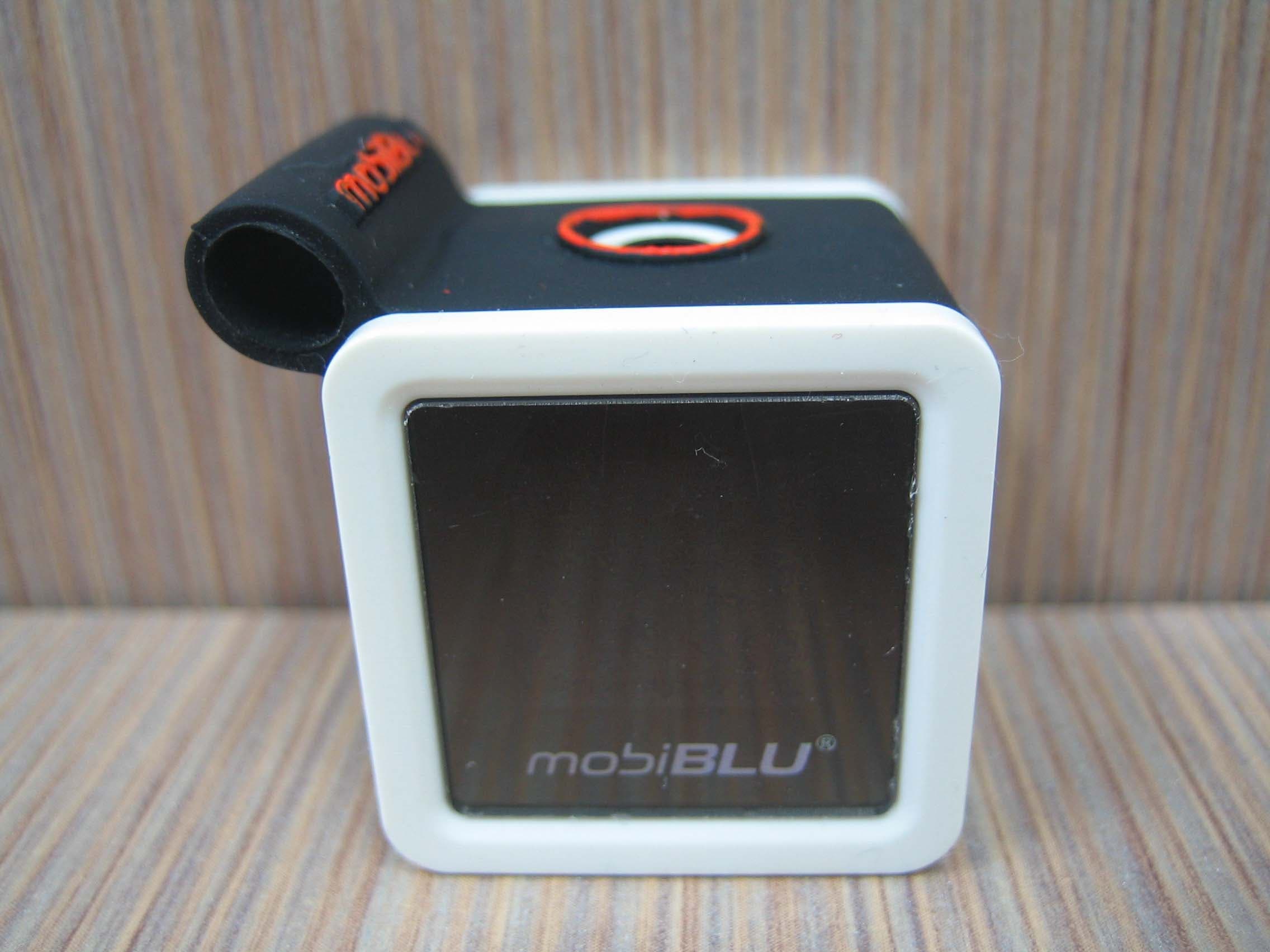
PCMCUBISTO
Sep 24, 2006Digital Audio Player
Equipment Class
JBP - Part 15 Class B Computing Device Peripheral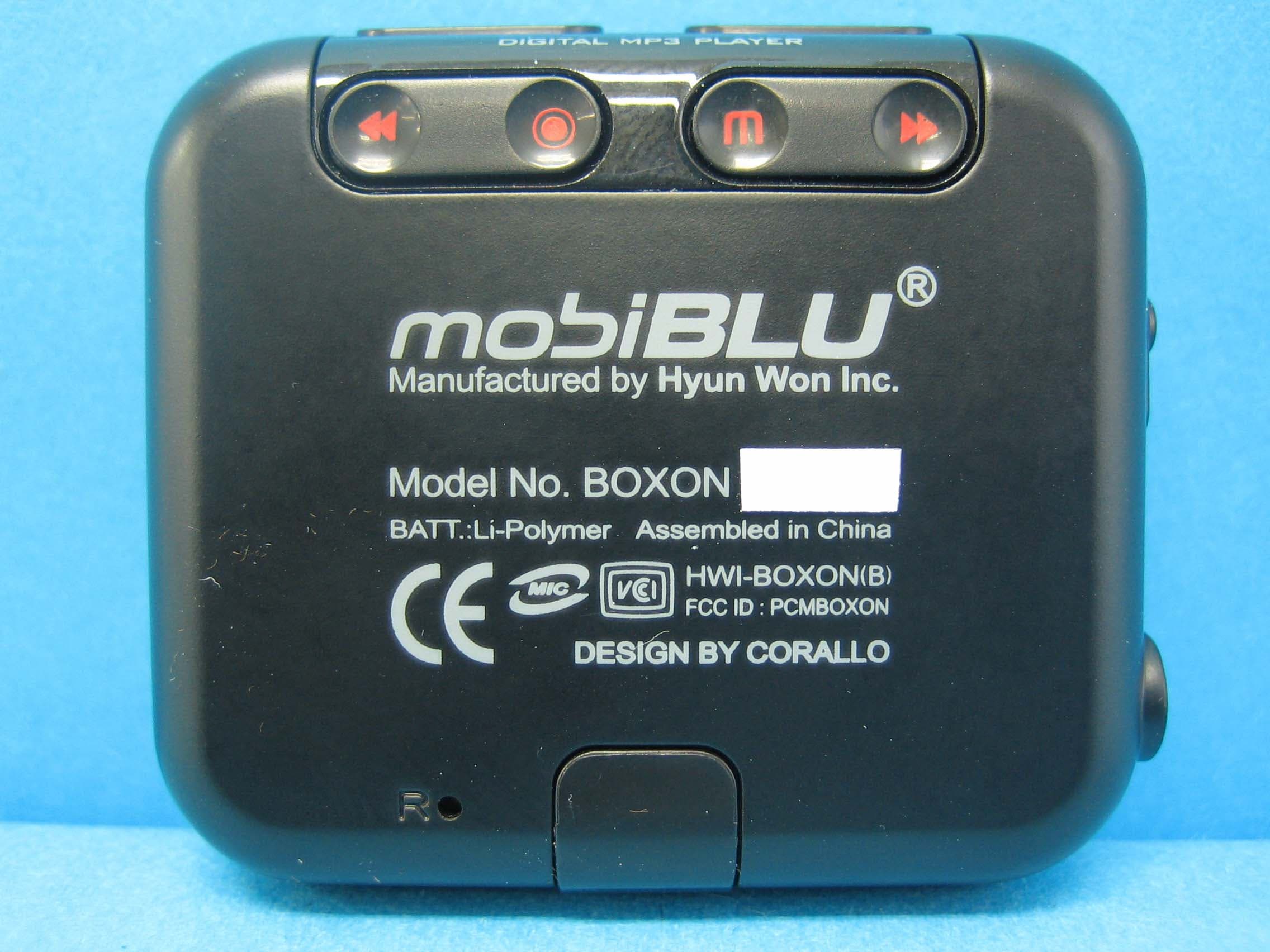
PCMBOXON
Sep 14, 2006Digital Audio Player
Equipment Class
JBP - Part 15 Class B Computing Device Peripheral
PCMDAH-2100
Jun 15, 2006Digital Audio Player
Equipment Class
JBP - Part 15 Class B Computing Device Peripheral
PCMUS2
Jun 11, 2006MP3 PLAYER
Equipment Class
JBP - Part 15 Class B Computing Device Peripheral
PCMCUBE2
Apr 23, 2006MP3 Player
Equipment Class
JBP - Part 15 Class B Computing Device Peripheral