PDN-DTL-1Spread Spectrum Connectivity Card
Microsoft Corporation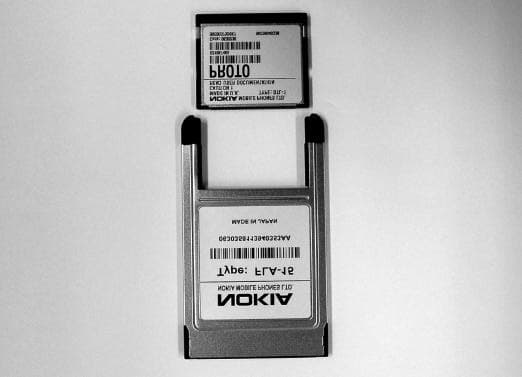
Click to zoom
Application Details
- Equipment Class
- DSS - Part 15 Spread Spectrum Transmitter
- Date of Grant
- Dec 18, 2000
- Application Purpose
- Original Equipment
- Date of Application
- Dec 18, 2000
- Equipment Note
- Spread Spectrum Connectivity Card
- Frequency Range
- 2402.00000000 - 2480.00000000
- Company
- Microsoft Corporation
- Country
- United States
Documents & Files
Document Text
Text extracted from the exhibit documents filed with the FCC. Open a document above to read the original.
Users Manual
IMPORTANT NOTE! FCC Radio Frequency Exposure Statement This equipment generates and radiates radio-frequency energy. To comply with FCC RF exposure compliance requirements, the following antenna installation and device operating configurations must be satisfied: 1. Users are not permitted to make changes or modify the system in any way. 2. Connecting external antennas to DTL-1 is prohibited.
Users Manual
(NOTE! This document is DRAFT) Nokia Connectivity Card DTL-1 User’s guide For your safety Read these simple guidelines. Breaking the rules may be dangerous or illegal. Further detailed information is given in this user’s guide. Road safety Do not use the Nokia Connectivity Card while driving; park the vehicle first. Interference All Nokia Connectivity Cards may receive interference, which could affect performance. Hospitals and aircraft's Nokia Connectivity Cards can cause interference. Observe restrictions for use in these areas. Sw itch off w hen refuelling Do not use the Nokia Connectivity Card at a refuelling point. Do not use near fuel or chemicals. Sw itch off near blasting Do not use the Nokia Connectivity Card where blasting is in progress. Observe restrictions, and follow any regulations or rules. Use sensibly Use only in the normal operating position. Use qualified service Only qualified service personnel must repair equipment. Accessories Use approved accessories only. Do not connect incompatible products. Water resistance Your Nokia Connectivity Card is NOT water-resistant. The Nokia Connectivity Card is not covered under warranty for damage by any liquid substance. Make backup copies Remember to make backup copies of all important data. Connecting to other devices When connecting to any other device, read its user's guide for detailed safety instructions. Do not connect incompatible products. DECLARATION OF CONFORMITY We, NOKIA MOBILE PHONES Ltd declare under our sole responsibility that the product DTL-1 is in conformity with the provisions of the following Council Directive: 1999/5/EC. Copyright © Nokia Mobile Phones 2000. All rights reserved. Reproduction, transfer, distribution or storage of part or all of the contents in this document in any form without the prior written permission of Nokia is prohibited. Nokia and Nokia Connecting People are registered trademarks of Nokia Corporation. Other product and company names mentioned herein may be trademarks or tradenames of their respective owners. Nokia operates a policy of continuous development. Nokia reserves the right to make changes and improvements to any of the products described in this document without prior notice. Under no circumstances shall Nokia be responsible for any loss of data or income or any special, incidental, consequential or indirect damages howsoever caused. The contents of this document are provided “as is”. Except as required by applicable law, no warranties of any kind, either express or implied, including, but not limited to, the implied warranties of merchantability and fitness for a particular purpose, are made in relation to the accuracy, reliability or contents of this document. Nokia reserves the right to revise this documents or withdraws it at any time without prior notice. The availability of particular products may vary by region. Please check with the Nokia dealer nearest to you. Introduction Nokia Connectivity Card is a PC Card (and a Compact Flash) device that establishes a wireless radio link (Bluetooth) between PCs with PC card or Compact Flash™ (CF+™) slot using Bluetooth wireless technology. Bluetooth wireless technology provides a virtual network of devices that can exchange data using microwave radio frequency, 2.4 GHz unlicensed ISM band. The purpose of this product is to enhance people’s daily data communication life by removing cables and thus adding freedom and flexibility. With Nokia Connectivity Card and Bluetooth compatible phones or other devices user can handle emails, web browsing, fax and calendar and contact synchronizing file transfer easily without physical cable connection and direct line-of-sight. Bluetooth is a global standard for wireless connectivity. The main members of Bluetooth consortium are Nokia, Ericsson, IBM, Intel and Toshiba. Afterwards companies like 3Com, Psion, Dell, Compaq, Casio and Seiko-Epson have also joined to Bluetooth. Bluetooth technology allows for the replacement of the many proprietary cables that connect one device to another with one universal short-range radio link (radio range up to 10m). This enlarges freedom and flexibility of using different devices and peripherals. For instance, phone number and calendar data can be easily transferred from mobile phone to laptop and vice versa. Bluetooth technology doesn’t require line-of-sight connection as infrared does. 360 degrees of freedom makes Bluetooth devices extremely flexible and easy to use. To achieve real benefit for user, the key characteristics of Bluetooth devices would be interoperability, reliability and simplicity. Bluetooth Connectivity The Nokia Connectivity Card employs the data transmission capabilities of a Bluetooth Connectivity in order to send and receive data, to browse the Internet, and to establish connections with other computers, for example. Data connections can be made from most locations where your Nokia Connectivity Card operates. However, it is recommended that you move the Nokia Connectivity Card to a location where the strongest possible signal can be obtained. When the signal is strong, data transmission is efficient. The following factors may impair wireless connections: Noise Electronic appliances and equipment can cause radio interference. Also in areas where Nokia Connectivity Cards are prevalent, other Nokia Connectivity Cards can impair the wireless connection. Electrostatic discharge A discharge of static electricity from a finger or a conductor may cause erroneous functions in electrical devices. The discharge may result in unstable software operation. Network connections may become unreliable, data may be corrupted, and the transmission halted. In this case, end the existing connection (if any), stop the Nokia Connectivity Card, and remove it from the PC card slot. Then re-insert the Nokia Connectivity Card into the PC card slot and try connecting again. Dead spots and dropouts Dead spots are areas where radio signals cannot be received. Dropo…
Text truncated - open the document above for the full version.
External Photos
PHOTOGRAPHS 1 (3) TAC Tampere TAC Tampere Nokia Mobile Phones Ltd. Box 68 FIN-33721 TAMPERE FINLAND Tel. +358 10 505 6800 Fax. +358 10 505 6880 PHOTOGRAPHS 2 (3) TAC Tampere TAC Tampere Nokia Mobile Phones Ltd. Box 68 FIN-33721 TAMPERE FINLAND Tel. +358 10 505 6800 Fax. +358 10 505 6880 PHOTOGRAPHS 3 (3) TAC Tampere TAC Tampere Nokia Mobile Phones Ltd. Box 68 FIN-33721 TAMPERE FINLAND Tel. +358 10 505 6800 Fax. +358 10 505 6880
Internal Photos
PHOTOGRAPHS 1 (2) TAC Tampere TAC Tampere Nokia Mobile Phones Ltd. Box 68 FIN-33721 TAMPERE FINLAND Tel. +358 10 505 6800 Fax. +358 10 505 6880 PHOTOGRAPHS 2 (2) TAC Tampere TAC Tampere Nokia Mobile Phones Ltd. Box 68 FIN-33721 TAMPERE FINLAND Tel. +358 10 505 6800 Fax. +358 10 505 6880
Parts List/Tune Up Info
CONFIDENTIAL 1 (1) NMP/DCU/TampereNovember 15, 2000 LIST OF ACTIVE CIRCUIT DEVICES, THEIR SYMBOLS AND FUNCTIONS FCC ID: PDN-DTL-1 Table 1. Active devices on main PWB SECTIONREFERENCEAPPLICATIONFREQUENCY PCMCIA interface ASIC D101PCMCIA interface logic EEPROMD102 Reset bufferD103 Linear regulatorN101 Radio moduleV101See Table 2 Table 2. Active devices on radio module (multi-chip module V101) SECTIONREFERENCEAPPLICATIONFREQUENCY RF TransceiverD120Bluetooth-RF-ASIC RF transceiver for ISM-band 2400-2483 MHz High slope single VCO operation for RX and TX Four fully integrated supply voltage regulators LNA and mixer on chip Reference crystal oscillator on chip 13 MHz UHF crystal oscillator on chip 1150 MHz CPUD200Bluetooth-BB-ASIC Sleep-oscillator32.768 kHz SwitchN180RF switch
Test Report
TEST REPORT: DTL1_FCC.DOC 1 (32) TAC Tampere The test results are valid for the tested unit(s) only. This report shall not be reproduced except in full, without the written permission of the testing laboratory. TAC Tampere Nokia Mobile Phones Ltd. Box 68 FIN-33721 TAMPERE FINLAND Tel. +358 10 505 6800 Fax. +358 10 505 6880 Test Report for DTL-1 and FLA-15 TAC Tampere Nokia Mobile Phones Ltd. Box 68 FIN-33721 TAMPERE FINLAND Tel. +358 10 505 6800 Fax. +358 10 505 6880 TEST REPORT: DTL1_FCC.DOC 2 (32) TAC Tampere The test results are valid for the tested unit(s) only. This report shall not be reproduced except in full, without the written permission of the testing laboratory. TAC Tampere Nokia Mobile Phones Ltd. Box 68 FIN-33721 TAMPERE FINLAND Tel. +358 10 505 6800 Fax. +358 10 505 6880 CONTENTS 1CUSTOMER INFORMATION.................................................................................................................... 4 2EUT AND ACCESSORY INFORMATION.................................................................................................5 2.1EUT DESCRIPTION...............................................................................................................................5 2.2EUT AND ACCESSORIES....................................................................................................................... 5 2.3S OFTWARE.......................................................................................................................................... 5 3SUMMARY OF TEST RESULTS .............................................................................................................. 6 4STANDARDS AND MEASUREMENT METHODS.................................................................................... 7 4.1S ELECTION OF OPERATION MODE FOR TESTS......................................................................................... 7 5TEST SETUPS.......................................................................................................................................... 7 5.1S ETUP A (CONDUCTED MEASUREMENTS, HOPPING DISABLED) ................................................................ 7 5.1.1 Operational description .................................................................................................................. 7 5.1.2 Block diagram ................................................................................................................................ 7 5.2S ETUP B (CONDUCTED MEASUREMENTS, HOPPING ENABLED)................................................................. 8 5.2.1 Operational description .................................................................................................................. 8 5.2.2 Block diagram ................................................................................................................................ 8 5.3S ETUP C (RADIATED MEASUREMENTS, HOPPING ENABLED) .................................................................... 8 5.3.1 Operational description .................................................................................................................. 8 5.3.2 Block diagram ................................................................................................................................ 9 6TEST RESULTS........................................................................................................................................ 9 6.1AC POWERLINE CONDUCTED EMISSIONS (§15.207) ............................................................................... 9 6.1.1 Limit................................................................................................................................................ 9 6.1.2 EUT operation mode ...................................................................................................................... 9 6.1.3 EUT test setup ............................................................................................................................... 9 6.1.4 Emission measurement data ....................................................................................................... 10 6.2C ARRIER FREQUENCY SEPARATION (§15.247A1)................................................................................. 11 6.2.1 EUT operation mode .................................................................................................................... 11 6.2.2 Limits and results ......................................................................................................................... 11 6.2.3 Screen shot .................................................................................................................................. 11 6.3N UMBER OF HOPPING FREQUENCIES (§15.247A2) ............................................................................... 12 6.3.1 EUT operation mode .................................................................................................................... 12 6.3.2 Limits and results ......................................................................................................................... 12 6.3.3 Screen shot .................................................................................................................................. 12 6.4T IME OF OCCUPANCY (§15.247A3) ..................................................................................................... 13 6.4.1 EUT operation mode .................................................................................................................... 13 6.4.2 Limits and results ......................................................................................................................... 13 6.4.3 Screen shots ................................................................................................................................ 14 6.520 DB BANDWIDTH (§15.247A1) .................................…
Text truncated - open the document above for the full version.
Test Report
DTL1_CORR_PAGE.DOC 1 (2) TAC Tampere The test results are valid for the tested unit(s) only. This report shall not be reproduced except in full, without the written permission of the testing laboratory. TAC Tampere Nokia Mobile Phones Ltd. Box 68 FIN-33721 TAMPERE FINLAND Tel. +358 10 505 6800 Fax. +358 10 505 6880 CORRECTION TO TEST REPORT: DTL1_FCC.DOC ERROR The values in first table in test report section 6.6.2 are not correct. CORRECTION The correct values are copied from the calculation table to the value table. The corrected page replaces the old one. DTL1_CORR_PAGE.DOC 2 (2) TAC Tampere The test results are valid for the tested unit(s) only. This report shall not be reproduced except in full, without the written permission of the testing laboratory. TAC Tampere Nokia Mobile Phones Ltd. Box 68 FIN-33721 TAMPERE FINLAND Tel. +358 10 505 6800 Fax. +358 10 505 6880 6.6.2 Limits and results Peak output power EUT Channel Limit (W) Test result (W) 2 0.00103 40 0.00115 80 ≤ 1 0.00073 EUT channel Measured value [dBm] Cable attenuation [dB] Power output [dBm] Power output [W] 2 -0.08 0.2 0.12 0.00103 40 0.42 0.2 0.62 0.00115 80 -1.57 0.2 -1.37 0.00073 6.6.3 Screen shots IN1 VBW 1 MHz RBW 1 MHz Span 5 MHzCenter 2.402 GHz500 kHz/ Ref Lvl 10 dBm Ref Lvl 10 dBmSWT 5 msUnit dBm 1MA A RF Att 40 dB 1MAX -70 -60 -50 -40 -30 -20 -10 0 10 1 Marker 1 [T1] -0.08 dBm 2.40217535 GHz 1 [T1] -0.08 dBm 2.40217535 GHz Date: 28.SEP.2000 11:22:30 Picture 9. Peak output power on channel 2
Test Report
TEST REPORT: DTL1_FCC2.DOC 1 (13) TAC Tampere The test results are valid for the tested unit(s) only. This report shall not be reproduced except in full, without the written permission of the testing laboratory. TAC Tampere Nokia Mobile Phones Ltd. Box 68 FIN-33721 TAMPERE FINLAND Tel. +358 10 505 6800 Fax. +358 10 505 6880 Test Report for DTL-1 and FLA-15 TAC Tampere Nokia Mobile Phones Ltd. Box 68 FIN-33721 TAMPERE FINLAND Tel. +358 10 505 6800 Fax. +358 10 505 6880 TEST REPORT: DTL1_FCC2.DOC 2 (13) TAC Tampere The test results are valid for the tested unit(s) only. This report shall not be reproduced except in full, without the written permission of the testing laboratory. TAC Tampere Nokia Mobile Phones Ltd. Box 68 FIN-33721 TAMPERE FINLAND Tel. +358 10 505 6800 Fax. +358 10 505 6880 CONTENTS 1CUSTOMER INFORMATION.................................................................................................................... 3 2EUT AND ACCESSORY INFORMATION.................................................................................................4 2.1EUT DESCRIPTION...............................................................................................................................4 2.2EUT AND ACCESSORIES....................................................................................................................... 4 2.3S OFTWARE.......................................................................................................................................... 4 3SUMMARY OF TEST RESULTS .............................................................................................................. 4 4STANDARDS AND MEASUREMENT METHODS.................................................................................... 5 4.1S ELECTION OF OPERATION MODE FOR TESTS......................................................................................... 5 5TEST SETUPS.......................................................................................................................................... 5 5.1S ETUP A (CONDUCTED MEASUREMENTS, HOPPING DISABLED) ................................................................ 5 5.1.1 Operational description .................................................................................................................. 5 5.1.2 Block diagram ................................................................................................................................ 5 5.2S ETUP B (CONDUCTED MEASUREMENTS, HOPPING ENABLED)................................................................. 6 5.2.1 Operational description .................................................................................................................. 6 5.2.2 Block diagram ................................................................................................................................ 6 6TEST RESULTS........................................................................................................................................ 6 6.1T IME OF OCCUPANCY (§15.247F).......................................................................................................... 6 6.1.1 EUT operation mode ...................................................................................................................... 6 6.1.2 Limits and results ........................................................................................................................... 6 6.1.3 Screen shots .................................................................................................................................. 7 6.1.4 EUT operation mode ...................................................................................................................... 8 6.1.5 Limits and results ........................................................................................................................... 8 6.1.6 Screen shots .................................................................................................................................. 9 6.2P OWER DENSITY (§15.247D) .............................................................................................................. 10 6.2.1 EUT operation mode .................................................................................................................... 10 6.2.2 Limits and results ......................................................................................................................... 11 6.2.3 Screen shots ................................................................................................................................ 11 7TEST EQUIPMENT ................................................................................................................................. 13 TEST REPORT: DTL1_FCC2.DOC 4 (13) TAC Tampere The test results are valid for the tested unit(s) only. This report shall not be reproduced except in full, without the written permission of the testing laboratory. TAC Tampere Nokia Mobile Phones Ltd. Box 68 FIN-33721 TAMPERE FINLAND Tel. +358 10 505 6800 Fax. +358 10 505 6880 2 EUT AND ACCESSORY INFORMATION 2.1 EUT description The EUT is a Connectivity Card (DTL-1) operating on the 2.4GHz – 2.4835GHz band using Bluetooth technology. It comes with a separate PC Card adapter (FLA-15) which allows inserting it to a computer with a PCMCIA slot. The EUT has an integral antenna and no external connections or controls. The EUT is in control of the software delivered with the EUT. 2.2 EUT and accessories The table below lists all EUTs and accessories used in the tests. Later in this test report, only numbers in the last column are used to refer to the devices in each test. 2.3 Software The computers were equipped with test software provided by the customer. The software was used to control the EUT in the tests. NameTypeS/NNumber EUTConnectivity CardDTL-103011 PC Card AdapterFLA-1503012 AccessoriesLaptop comp…
Text truncated - open the document above for the full version.
Test Report
1 (11) NMP/DCU/TampereFebruary 18, 2001 Processing Gain Document for DTL-1 2 (11) NMP/DCU/TampereFebruary 18, 2001 1. SCOPE This document describes the requirements and measurement results for the processing gain requirement given for the US market by FCC, Part 15.247. This includes the description of the test setup. FCC proposes the jamming margin test method to be used to demonstrate the processing gain of the DS component. FCC's proposed test setup: BT TX DUT RX CW Signal Gen . BER Power Meter J S The text in the FCC Part 15.247 section describes the measurement procedure as follows: "As measured using the CW jamming margin method: a signal generator is stepped in 50 kHz increments across the passband of the system, recording at each point the generator level required to produce the recommended Bit Error Rate (BER). This level is the jammer level. The output power of the intentional radiator is measured at the same point. The jammer to signal ratio (J/S) is then calculated, discarding the worst 20% of the J/S data points. The lowest remaining J/S ratio is used to calculate the processing gain, as follows: Gp = (S/N)o + Mj + Lsys, where Gp = processing gain of the system, (S/N)o = signal to noise ratio required for the chosen BER, Mj = J/S ratio, and Lsys = system losses. Note 3 (11) NMP/DCU/TampereFebruary 18, 2001 that total losses in a system, including intentional radiator and receiver, should be assumed to be no more than 2 dB. (...) Hybrid systems that employ a combination of both direct sequence and frequency hopping modulation techniques shall achieve a processing gain of at least 17 dB from the combined techniques." 2. REQUIREMENT FCC (Part 15.247 document) requires for FH systems operating in the 2.4 GHz band to use at least 75 hopping channels. During inquiry and paging procedure Bluetooth only uses 32 hopping channels. In this state Bluetooth is regarded as a hybrid FH/DS by FCC. For such systems FCC requires a minimum processing gain of 17 dB, resulting from FH in combination with DS. As 32 channels are used during inquiry and paging the resulting processing gain from the FH operation is 15 dB: dB MHz MHz B B PG m s FH 1532 1 32 ≈=== The missing 2 dB should be gained by the DS operation of the access code during paging and inquiry. These 2 dB must be demonstrated by a measurement. 4 (11) NMP/DCU/TampereFebruary 18, 2001 3. ABBREVIATIONS Bluetooth Bluetooth technology, created by an industry consortium, works in the 2,45GHz ISM band, with a gross data rate of about1Mbit/s, frequency hopping 1600 times a second over 79 channels being employed with a 1 MHz channel raster. BTBluetooth DSDirect Sequence FHFrequence Hopping FCCFederal Communications Commission DUTDevice under test 5 (11) NMP/DCU/TampereFebruary 18, 2001 4. TEST SETUP AbbreviationEquipmentDetails SMESignal GeneratorRohde&Schwarz SME03, 5kHz-3GHz SMIQSignal GeneratorRohde&Schwarz SMIQ03E, 300kHz-3,3GHz AMIQIQ Modulation GeneratorRohde&Schwarz AMIQ FER CounterUniversal CounterAgilent 53131A ComboxF-Bus connection to PCNokia Communication Interface RF SME RF M1 M2 M3 M4 SMIQ AMIQ I / Q I / Q Cir Div 1 ANT DUT GPP - 10 dB - 10 dB 50 Ω ΩΩ Ω Combox PC GPP 9 / TDI FER Counter A B Frame Error 6 (11) NMP/DCU/TampereFebruary 18, 2001 4.1 Test Procedure The following test procedure is used to verify the processing gain of the DS component for the receiver: a).Hopping off. BT TX (signal generator SMIQ) at f c arbitrary chosen from the inquiry/paging hopping sequence. b).CW jammer starts at f c c).BT TX (signal generator SMIQ) sends access codes (see 4.2) at signal level S. The timing of the TX signal is alligned to the scan window of the DUT RX. d).Based on the correlator output (Sync found) of the DUT RX, frame errors are counted e).Jammer level J iss increased until FER requirement is violated (≥ 1x10e-3) The FER will be calculated based on 1x10e4 transmitted access codes. f).This J / S level is recorded g).Jammer signal frequency 50 kHz is increased/deacreased h). c – g is repeated until the J/S values are comfortably compliant i).The processing gain is calculated as described in the FCC procedure: Discarding the worst 20 % of the J/S data points, The lowest remaining J/S ratio is used to calculate the processing gain, as follows: SYS j L S J N S PG+ + = 0 , j).a - i is repeated until all access codes (see 4.2) are tested 7 (11) NMP/DCU/TampereFebruary 18, 2001 4.2 Tested Access Codes It is clear that there are 'good' and 'bad' access codes from processing gain point of view. FCC's processing gain requirement will be shown for the codes that are given in the following table: Access CodesLAP GIAC9E8B33 LIAC9E8B00 'Worst case' codes000000 FFFFFF 65B333 8 (11) NMP/DCU/TampereFebruary 18, 2001 5. MEASUREMENT RESULTS 5.1 Device Under Test ManufacturerNokia Mobile Phones Ltd. TestobjectBluetooth module DUTBT101 DUT Version4.0 TestplatformBT101 Testboard A BT101 radio module testboard is used in testing instead of DTL-1 product because of extra I/O pins needed for test control, synchronization and correlator output. The BT101 radio module on test board is similar to the one in DTL-1 and contains all circuitry which affects processing gain. 5.2 Pass Criteria The processing gain PG, as measured, from the DS operation must be greater than 2 dB. SYS j L S J N S PG+ + = 0 , 5.3 Testing Results 5.3.1 Signal to Noise Ratio (S/N) 0 (S/N) 0 is the required signal to noise ratio at the receiver input for a BER 1x10e-3. The ideal equation/curve for GFSK is used to determine this value. For the BT101 version 4.0 a signal to noise ratio of 16,4 dB is given. The system loss L SYS of maximal 2 dB is included. 5.3.2 Jammer to Signal Ratio (J/S) J (J/S) J is measured according to the test setup. 9 (11) NMP/DCU/TampereFebruary 18, 2001 The DUT is set in receive mode without hopping. The signal generator is set to transmit at f c arbitrary chosen from the inquiry/paging hopping sequence. CW jammer st…
Text truncated - open the document above for the full version.
Test Setup Photos
TEST SETUP PHOTOS 1 (3) TAC Tampere The test results are valid for the tested unit(s) only. This report shall not be reproduced except in full, without the written permission of the testing laboratory. TAC Tampere Nokia Mobile Phones Ltd. Box 68 FIN-33721 TAMPERE FINLAND Tel. +358 10 505 6800 Fax. +358 10 505 6880 TEST SETUP PHOTOS 2 (3) TAC Tampere The test results are valid for the tested unit(s) only. This report shall not be reproduced except in full, without the written permission of the testing laboratory. TAC Tampere Nokia Mobile Phones Ltd. Box 68 FIN-33721 TAMPERE FINLAND Tel. +358 10 505 6800 Fax. +358 10 505 6880 TEST SETUP PHOTOS 3 (3) TAC Tampere The test results are valid for the tested unit(s) only. This report shall not be reproduced except in full, without the written permission of the testing laboratory. TAC Tampere Nokia Mobile Phones Ltd. Box 68 FIN-33721 TAMPERE FINLAND Tel. +358 10 505 6800 Fax. +358 10 505 6880
Test Setup Photos
TEST SETUP PHOTOS 1 (3) TAC Tampere The test results are valid for the tested unit(s) only. This report shall not be reproduced except in full, without the written permission of the testing laboratory. TAC Tampere Nokia Mobile Phones Ltd. Box 68 FIN-33721 TAMPERE FINLAND Tel. +358 10 505 6800 Fax. +358 10 505 6880 TEST SETUP PHOTOS 2 (3) TAC Tampere The test results are valid for the tested unit(s) only. This report shall not be reproduced except in full, without the written permission of the testing laboratory. TAC Tampere Nokia Mobile Phones Ltd. Box 68 FIN-33721 TAMPERE FINLAND Tel. +358 10 505 6800 Fax. +358 10 505 6880 TEST SETUP PHOTOS 3 (3) TAC Tampere The test results are valid for the tested unit(s) only. This report shall not be reproduced except in full, without the written permission of the testing laboratory. TAC Tampere Nokia Mobile Phones Ltd. Box 68 FIN-33721 TAMPERE FINLAND Tel. +358 10 505 6800 Fax. +358 10 505 6880
Contact Information
Applicant
Hasnain Syed(Director, EMC, SI and RF Compliance)
Technical Contact
Non-Technical Contact
TAC TampereHeli Makinen
[email protected]+358 50 553 4776
Test Firm
TCC TampereJari Jantunen
Technical Specifications
| # | Rule Parts | Frequency Range | Power Output |
|---|---|---|---|
| 1 | 15C | 2.40 GHz - 2.48 GHz | 1.15 mW |
Other Applications from Microsoft Corporation

PDNRM-1020
Jul 07, 2014GSM/WCDMA cellular device w/BT, BLE, WLAN
Equipment Class
JBP - Part 15 Class B Computing Device Peripheral
PDNRM-1018
Jul 06, 2014GSM/WCDMA cellular device w/BT, BLE, WLAN
Equipment Class
DSS - Part 15 Spread Spectrum Transmitter
PDNRM-975
May 27, 2014GSM/WCDMA/LTE cellular device w/BT, BLE, WLAN
Equipment Class
DTS - Digital Transmission System
PDNRM-974
May 12, 2014GSM/WCDMA/LTE cellular device w/BT, BLE, WLAN
Equipment Class
DTS - Digital Transmission System
PDNRM-979
Mar 09, 2014GSM/WCDMA cellular device w/BT, BLE, WLAN
Equipment Class
DTS - Digital Transmission System