PFK-500-01Color Meter with Wireless Flash Control Transcieve
Sekonic Corporation
Click to zoom
Application Details
- Equipment Class
- DSR - Part 15 Remote Control/Security Device Transceiver
- Date of Grant
- Jan 07, 2008
- Application Purpose
- Original Equipment
- Date of Application
- Jan 07, 2008
- Equipment Note
- Color Meter with Wireless Flash Control Transcieve
- Frequency Range
- 344.04000000 - 354.00000000
- Company
- Sekonic Corporation
- Country
- Japan
Documents & Files
Document Text
Text extracted from the exhibit documents filed with the FCC. Open a document above to read the original.
Users Manual
1 PRODIGICOLOR C-500/C-500R Operating Manual 2 1. Parts Designation Light Sensor Liquid Crystal Display (LCD) POWER button (ON/OFF switch) PRESET button (“A” in radio sub-channel setting) MODE button (“C” in radio sub-channel setting) MENU button Flash Synchro terminal MEASURE/OK button Jog Wheel SET K button (“B” in radio sub-channel setting) DISPLA Y button (“D” in radio sub-channel setting) /BACK button Battery Cover Latch Battery Compartment Cover Battery Compartment Strap eyelet Tripod Socket 3 2. Explanation of the Liquid Crystal Display C-500/C-500R Measuring Mode Icons Ambient Auto-Reset Cordless Flash Cord Flash Wireless Flash Radio Triggering Mode Battery Power Indicator (Displayed) Battery power level is good (Displayed) Battery power level is low. Have a spare battery ready (Blinking) Replace battery immediately Flash Measurement Range Icons (Displayed)Auto-Reset Cordless Flash Mode or Cord Flash Mode (Displayed) H Range Select (Displayed) L Range Select DIGITAL/FILM Mode Icons (Displayed) DIGITAL Mode Select (Displayed) FILM Mode Select Selected Color Temperature Display (Displayed) Set-up Color temperature 4 Shutter Speed Display (Displayed)Auto-Reset Cordless Flash Mode or Cord Flash Mode “S” Appears when shutter speed is in full seconds Example: 1s is displayed for shutter speed 1 second. 60 is displayed for shutter speed 1 / 60 seconds. Preset Color / White Balance Display and Contrast Icons (Displayed) Selected Preset Function (Selected Preset No. 1~19) (Displayed) Used Monitoring facility Dot Matrix Display for Preset Name, Menu and Illuminance A menu name is displayed during menu selection. A Preset name is displayed at the time of a Preset setup. The unit of illumination is displayed only when Ix or FC is set up with the Illumi. Sub menu of a custom-made setup. LB, Measured Color Temperature and Illuminance Display LB index, LB filter, and a color temperature are displayed by display mode. A simple illumination display is displayed only when Ix or FC is set up with the Illumi. Sub menu of the custom-made setup. In the error besides the display range and the measurement range, u, Under or o, and Over are displayed. u, Under Appears when below display range “u, Under” Blinks when under measured below measurement range o, Over Appears when above display range “o, Over” Blinks when over measured above measurement range CC Display CC index and CC filter are displayed by display mode. Radio triggering channel and Quad-triggering Zone Display (Displayed) Wireless Flash Radio Triggering Mode The main channel which chose 1~16 channels is displayed. The main channel (17~32) which chose 17~32 channels, and a sub-channel (A~D) are displayed. Auto Electro-Luminescent Display (EL) In low light (160lx or less), a green backlight will automatically illuminate the entire LCD. The LCD will not be automatically illuminated during measuring, in Cordless Flash mode or Wireless flash radio triggering mode. The Electro-luminescent backlight will automatically turn off 20 seconds after last operation. 5 FCC & IC compliance information: Warning: Changes or modifications to this unit not expressly approved by the party responsible for compliance could void the user's authority to operate the equipment. Note: This equipment has been tested and found to comply with the limits for a Class B digital device, pursuant To Part 15 of the FCC Rules. These limits are designed to provide reasonable protection against harmful interference in a residential installation. This equipment generates, uses, and can radiate radio frequency energy and, if not installed and used in accordance with the instruction, may cause harmful interference to radio communication. However, there is no guarantee that interference will not occur in a particular installation. If this equipment does cause harmful interference to radio or television reception, which can be determine by turning the equipment off and on, the user is encouraged to try to correct the interference by one or more of the following measures: * Reorient or relocate the receiving antenna. * Increase the separation between the equipment and receiver. * Consult the dealer or an experienced radio/TV technician for help. This device complies with Part 15 of the FCC rules and also with RSS-210 of Industry Canada. Operation is subject to the following two condition: (1) This device may not cause harmful interference, and (2) this device must accept any interference received, including interference that may cause undesired operation. FCC ID Number: PFK-500-01 IC ID Number: 3916A-500001
External Photos
External Photograph for C-500R 25/10/2007 SEKONIC CORPORATION Front Exterior C-500R Back Exterior C-500R Top Exterior Bottom Exterior Right Exterior Left Exterior
ID Label/Location Info
Back Exterior C-500R
Internal Photos
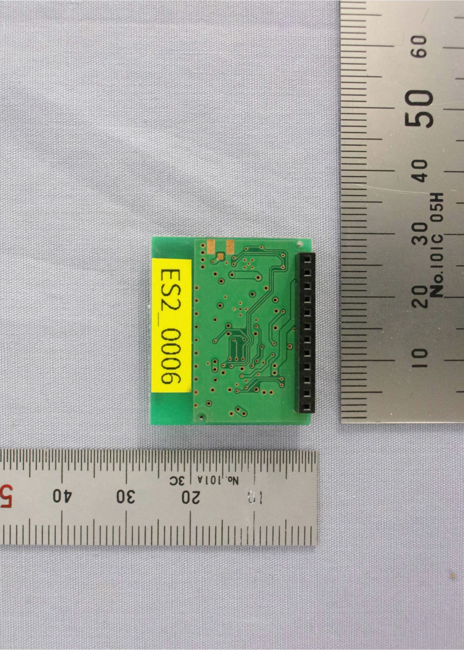
External Photograph for C-500R 26/10/2007 SEKONIC CORPORATION Basic Internal with Cover Back side without Battery Cover C-500R PCB 1 Top View PCB 1 Bottom View PCB 2 Top View PCB 2 Bottom View PCB 4 Top View PCB 4 Bottom View RF Module PCB Top View RF Module PCB Bottom View PCB 5 Top View PCB 5 Bottom View
Test Report
Test Report No. R-4935N-2 FCC ID: PFK-500-01 IC: 3916A-500001 APPLICANT Sekonic Corporation 7-24-14, Oiaumi-Gakuen-cho Nerima-ku, Tokyo, 178-8686 Japan TEST SPECIFICATIONS: FCC Rules and Regulations Part 15, Subpart C, Para. 15.231 RSS 210, Issue 7 TEST PROCEDURE: ANSI C63.4:2003/RSS-210, Issue 7 PURPOSE: The purpose of this test program was to demonstrate compliance of the C-500R Color Meter with Radio Module to the requirements of 15.231. TEST SAMPLE DESCRIPTION: BRANDNAME: Sekonic MODEL: C-500R TYPE: Color Meter with Radio Module POWER REQUIREMENTS: 3VDC via internal battery FREQUENCY BAND OF OPERATION: 344.04MHz to 354.0MHz MODULATION: OOK (On/Off Keying) TYPE OF TRANSMISSION: Control Signal (Pulse Recognition Codes) APPLICATION: Remote Triggering of Flashpack FREQUENCIES TESTED: 344.04MHz, 354.0MHz TESTS PERFORMED: 15.231 (b)/RSS-210 Annex 1, Spurious Radiated Emissions (30MHz to 3.6GHz) 15.231 (b)/RSS-210 Annex 1, Field Strength of Fundamental 15.231 (c) Occupied Bandwidth, 0.25% of Fundamental Frequency Test Report No. R-4935N-2 FCC ID: PFK-500-01 IC: 3916A-500001 RSS-210, Annex 1, A1.1.3, 99% bandwidth, 0.25% of Center Frequency Duty Cycle Determination NOTE: Testing was performed at 2 frequencies (low and high) within the operational band as required for devices operating within a 1 - 10MHz band but not exceeding 10MHz. TEST SAMPLE OPERATION: The device is normally manually operated and transmits a control signal for remote triggering of a flashpack. Normal operation of the EUT complies with the parameters required in Part 15, Subpart C, Section 15.231 and RSS 210 for momentary operated devices. For testing purposes only the EUT was configured to continuously transmit. TEST SAMPLE / TEST PROGRAM •The transmitter is manually activated and employs a switch that automatically deactivates the transmitter within 5 seconds of being released. CThe transmitter does not perform periodic transmissions at regularly predetermined intervals. CThe device can not be employed for RC purposes involving security. •The device uses an internal antenna. CThe fundamental field strength at 344.04MHz did not exceed 7252μV/M (Average) at a test distance of 3 meters. The fundamental field strength at 354.0MHz did not exceed 7667μV/M (Average) at a test distance of 3 meters. •The peak value of fundamental emissions did not exceed a peak field strength limit corresponding to 20dB above the maximum permitted average limit. CThe field strength of harmonic and spurious emissions did not exceed 725μV/M or 500μV/M as applicable for a fundamental frequency of 344.04MHz. The field strength of harmonic and spurious emissions did not exceed 766μV/M or 500μV/M as applicable for a fundamental frequency of 354.0MHz. No harmonic or spurious emissions were observed within 10dB of the specified limit at test distances of 1 or 3 meters. •Radiated Emissions from the EUT were measured in all three axis. The attached Radiated Emissions test data is representative of the worst case orientation. Test Report No. R-4935N-2 FCC ID: PFK-500-01 IC: 3916A-500001 TEST SAMPLE / TEST PROGRAM (continued) CThe device can operate within the range of 344.04 to 354.00MHz. The device was tested at the frequencies of 344.04MHz and 354.0MHz. The 20dB bandwidth and 99% bandwidth of emissions did not exceed 0.25% of the center operating frequency and was determined as follows: Fundamental Frequency=344.04MHz 0.25% of Center Frequency=0.860MHz 0.860 divided by 2=0.430MHz Bandwidth Range=Fundamental Frequency + and - 0.430MHz 344.04MHz - 0.430MHz=343.61MHz 344.04MHz + 0.430MHz=344.47MHz Bandwidth Range=343.61MHz - 344.47MHz Fundamental Frequency=354.0MHz 0.25% of Center Frequency=0.885MHz 0.884 divided by 2=0.4425MHz Bandwidth Range=Fundamental Frequency + and - 0.442MHz 354.0MHz - 0.442MHz=353.558MHz 353.5MHz + 0.442MHz=354.442MHz Bandwidth Range=353.558MHz - 354.442MHz DETERMINATION OF FIELD STRENGTH LIMITS The field strength limits shown below were calculated as instructed in Section 15.231. Fundamental Frequency: 344.04MHz Where F is the frequency in MHz, the formula for calculating the maximum permitted fundamental field strength for the band 260-470MHz, μV/m at 3 meters is as follows: 41.6667(F) - 7083.3333 =Field Strength Limit (μV/m) 41.6667 x 344.04=14335.011 14335.011 - 7083.3333=7252 Field Strength Limit=7252μV/m = 77.21dBuV/M The maximum permitted unwanted emission level is 20dB below the maximum permitted fundamental level which equals 725μV/m = 57.21dBuV/M. Test Report No. R-4935N-2 FCC ID: PFK-500-01 IC: 3916A-500001 TEST SAMPLE / TEST PROGRAM (continued) Field Strength Limit Calculations continued: Fundamental Frequency: 354.0MHz Where F is the frequency in MHz, the formula for calculating the maximum permitted fundamental field strength for the band 260-470MHz, μV/m at 3 meters is as follows: 41.6667(F) - 7083.3333 =Field Strength Limit (μV/m) 41.6667 x 353.5=14729.178 14729.178 - 7083.3333=7666.679 Field Strength Limit=7666.679μV/m = 77.69dBuV/M The maximum permitted unwanted emission level is 20dB below the maximum permitted fundamental level which equals 766.67μV/m = 57.69dBuV/M DETERMINATION OF DUTY CYCLE The transmitter controls were adjusted to maximize the transmitted duty cycle. The analyzer was set for a frequency span of 0Hz. The sweep time was then adjusted in order to display one full pulse train. The transmitter on time was then summed and compared to the time for one full cycle in order to obtain the duty cycle. The on times were determined as follows: The transmitter pulse train consisted of 3 identical pulse bursts. The individual pulses within each burst were measured and summed in order to obtain the total “on time”. Fundamental Frequency: 344.04MHz Transmitter On Time=.531milliseconds Transmitter Cycle Time= 8 milliseconds Transmitter Duty Cycle=6.637 % On Time divided by Cycle Time=Duty Cycle Factor .531divided by 8=0.06637 10 0.06637 converted to dB (LOG .06637)20=-23.56dB Duty Cycle Factor=-23.56dB Test Repor…
Text truncated - open the document above for the full version.
Test Setup Photos
R-4935N-2 FCC ID: PFK-500-01 IC: 3916A-500001 Radiated Emissions Setup Photographs R-4935N-2 FCC ID: PFK-500-01 IC: 3916A-500001 Radiated Emissions Setup Photographs R-4935N-2 FCC ID: PFK-500-01 IC: 3916A-500001 Occupied/99% Bandwidth Setup Photograph
Contact Information
Applicant
Hiroshi Harada(Director)
Technical Contact
Retlif Testing LaboratoriesScott Wentworth
[email protected]603-497-4600
101 New Boston Road · Goffstown, New Hampshire · United States
Non-Technical Contact
Retlif Testing LaboratoriesScott Wentworth
[email protected]603-497-4600
Test Firm
Retlif Testing LaboratoriesScott Wentworth
Technical Specifications
| # | Rule Parts | Frequency Range | Power Output |
|---|---|---|---|
| 1 | 15.231 | 344.04 MHz - 354 MHz | - |
Other Applications from Sekonic Corporation
PFK-TXMPR
Aug 04, 2026Radio TX Module.
Equipment Class
DXX - Part 15 Low Power Communication Device Transmitter
PFK-478-01
Aug 12, 2012Light Meter
Equipment Class
DSC - Part 15 Security/Remote Control Transmitter
PFK-RT32-03
Feb 28, 2012Remote Flash Control Transceiver
Equipment Class
DSR - Part 15 Remote Control/Security Device Transceiver
PFK-RT32-01
Sep 05, 2006Falsh Control Radio Module
Equipment Class
DSC - Part 15 Security/Remote Control Transmitter
PFK-758-01
May 16, 2006Eoposure / Light Meter
Equipment Class
DSC - Part 15 Security/Remote Control Transmitter