PFK-558-01Exposure/Light Meter
Sekonic Corporation
Click to zoom
Application Details
- Equipment Class
- DSC - Part 15 Security/Remote Control Transmitter
- Date of Grant
- Jul 17, 2003
- Application Purpose
- Original Equipment
- Date of Application
- Jul 17, 2003
- Equipment Note
- Exposure/Light Meter
- Frequency Range
- 344.00000000 - 354.00000000
- Company
- Sekonic Corporation
- Country
- Japan
Documents & Files
Document Text
Text extracted from the exhibit documents filed with the FCC. Open a document above to read the original.
Users Manual
DUALMASTER L-558/L-558 Operating Manual Blank page Congratulations on your purchase of a Sekonic DUALMASTER L-558/L-558CINE Exposure Meter The DUALMASTER L-558/L-558CINE is the latest addition to the extensive line of Sekonic Exposure Meters, which have been market leaders for over 50 years. The DUALMASTER was designed to offer more of what today’s photographer needs, and less of what they don’t. It offers flash and ambient exposure metering in both spot and incident modes. The DUALMASTER is the first multi-function meter to offer a 1-degree (nine element camera-quality) spot that measures reflected flash output as low as f/2.0. Along with its many unique features, the L- 558 is also capable of wireless flash triggering with an optional radio module. Utilizing rubber seals throughout the housing and controls of the meter, the DualMaster is water and moisture resistant. Although the meter can be used in rainy or wet conditions, it should not be used underwater. The large LCD panel makes reading the data easy and convenient; the panel illuminates automatically in low light surroundings. In order to retain the simple stylish look of the DUALMASTER, less frequently used functions and controls are confined to custom software settings. The DUALMASTER L-558 and L-558CINE is loaded with many features and control options. Since each of these features has a detailed explanation, this instruction booklet is extensive. We recommend that you read the manual to familiarize yourself with the potential of the meter. Once you have established which features and functions are important to you, refer to these sections only. The DUALMASTER has undergone extensive quality control at every step of manufacture. Please read this instruction manual thoroughly, to be able to take advantage of its many features and to obtain the long service life that it was designed to offer you. Thank you for investing in Sekonic. Table of Contents 1.Parts Designation ................................................................................................................ 1 2.Explanation of the Liquid Crystal Display (LCD) .................................................................. 2-4 3.Before Using ........................................................................................................................ 5-7 1.Attach the strap ......................................................................................................... 5 2.Inserting the battery ................................................................................................... 5 3.Checking battery capacity ......................................................................................... 5 4.Replacing battery during measurement or when using the memory function .......................................................................... 6 5.Auto Power Off function ............................................................................................. 6 6.Setting main ISO film speed ...................................................................................... 6 7.Setting second ISO film speed (ISO 2) ..................................................................... 6 8.Mode and setting Lock or Lock Off ............................................................................ 7 4.Basic Operation ................................................................................................................... 8-11 1.Incident or reflected spot measuring ......................................................................... 8 2.Setting measuring mode ........................................................................................... 9 3.When set for incident light ......................................................................................... 10 4.When set for reflected light (spot metering) .............................................................. 11 5.Measurment ........................................................................................................................ 12-22 1.Measuring Ambient Light ........................................................................................... 12 1-1Shutter Speed Priority mode ........................................................................... 12 1-2Aperture Priority mode .................................................................................... 13 1-3EV mode ......................................................................................................... 14 1-4Cinematography .............................................................................................. 15 2.Measuring Flash Light ............................................................................................... 17 2-1Cord Flash mode ............................................................................................. 17 2-2Auto Reset Cordless Flash mode ................................................................... 18 2-3Cord Multiple Flash (cumulative) mode ........................................................... 20 2-4Cordless Multiple Flash (cumulative) mode .................................................... 21 6.Advanced Functions ............................................................................................................ 23-37 1.Memory function ........................................................................................................ 23 2.Averaging function ..................................................................................................... 24 3.Brightness Difference function ................................................................................... 24 4.How to use an incident Illuminance (LUX or FC) Meter ............................................ 26 5.How to use a reflected luminance (cd/m 2 or FL) meter ............................................. 27 6.How to use Exposure compensation function .................................…
Text truncated - open the document above for the full version.
Cover Letter(s)
Date: June 17, 2003 Federal Communications Commission Equipment Approval Services Dear Sir/Madame: Pursuant to Section 0.459 of the Commission’s Rules; we, Sekonic Corporation, hereby request confidentiality as below; 1. Operational Description 2. Circuit Diagram 3. Block Diagram The reason of Confidentiality request is that trade secrets and proprietary information are enclosed in the above data, and the public disclosure of the data is harmful for us and will be made unjustifiable benefits to competitors. Sincerely, Kazuya Kuroi General Manager Quality Control Dept. SEKONIC CORPORATION
Cover Letter(s)
Description of product variants Date:03/6/27 Difference between the exposure meter model L-558 and L-558CINE as follows: The exposure meter model L-558 for photography and L-558CINE which are applying this time use the same electric wave module, and are the exposure meter which can make an electro flash emit light from the distant place. The difference between L-558 and L-558CINE is only a measurement data display, and the substrate loading parts except a liquid crystal display do not have a difference. - Liquid Crystal Display To L-558, L-558CINE is the model developed to movie photography, measured value is processed after digital conversion and by CPU (an illumination unit, luminosity unit, etc.), and they show. Since it is specializing in a movie relation, the special display was needed and the liquid crystal display has changed as follows. The difference portion to L-558 Therefore these different may not affect the compliance of Safety and/or EMC requirements. Kazuya Kuroi General Manager Quality Control Dept. SEKONIC CORPORATION
External Photos
Front Exterior L-558 Front Exterior L-558CINE Back Exterior Top Exterior Bottom Exterior Right Exterior Left Exterior
ID Label/Location Info
MADE IN PHILIPPINES MADE IN PHILIPPINES L - 558 MADE IN JAPAN L - 558 L - 558 MADE IN PHILIPPINES MADE IN PHILIPPINES L - 558CINE L - 558CINE FCC ID : PFK - 558 - 01 IC : 3916 - 558001 FCC ID : PFK - 558 - 01 IC : 3916 - 558001
Internal Photos
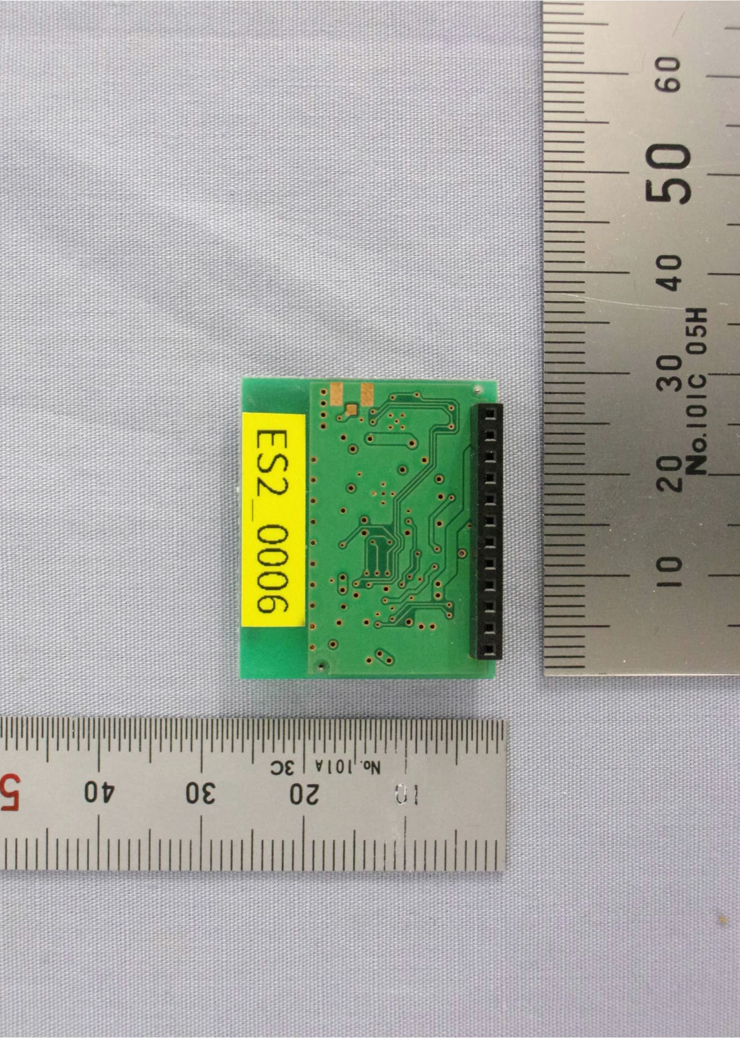
Basic Internal with Cover Basic Internal Back side without Battery Cover L-558 Back side without Battery Cover L-558CINE PCB 1 Top View PCB 1 Bottom view RF Module PCB Top View RF Module PCB Bottom View PCB 2&3 Top view RF Module Case ANT PCB side A ANT PCB side B
Test Report
JAPAN QUALITY ASSURANCE ORGANIZATION 21-25, KINUTA 1-CHOME, SETAGAYA-KU, TOKYO 157-8573 JAPAN PHONE +81-3-3416-0111, FAX +81-3-3416-9691 JQA APPLICATION NO.: 400-30174 Issue Date : July 1, 2003 Page 1 of 36 EMI TEST REPORT JQA APPLICATION NO. : 400-30174 Model No. : L-558CINE Type of Equipment : Exposure/Light Meter Regulations Applied : CFR 47 FCC Rules and Regulations Part 15 FCC ID : PFK-558-01 Applicant : SEKONIC CORPORATION Address : 2714 Oaza-ieda, Ikeda-machi, Kita-azumi-gun Nagano-ken 399-8601, Japan Manufacture : SEKONIC CORPORATION Address : 2714 Oaza-ieda, Ikeda-machi, Kita-azumi-gun Nagano-ken 399-8601, Japan Received date of EUT : June 5, 2003 Final Judgment : Passed Test results in this report are obtained in use of equipment that is traceable to National Institute of Advanced Industrial Science and Technology (AIST) of Japan and Communication Research Laboratory (CRL) of Japan. The test results only respond to the tested sample. This report should not be reproduced except in full, without the written approval of JQA EMC Engineering Dept. Testing Div. C O P Y JQA Application No. :400-30174 FCC ID :PFK-558-01 Model No. :L-558CINE Issue Date :July 1, 2003 Standard :CFR 47 FCC Rules Part 15 Page 2 of 36 JAPAN QUALITY ASSURANCE ORGANIZATION TABLE OF CONTENTS Page 1 Documentation 1.1 Test Regulation 3 1.2 General Information 3 1.3 Test Condition 4 – 8 1.4 EUT Modifications / Deviation from Standard 9 1.5 Test results 10 1.6 Summary 11 1.7 Test Configuration / Operation of EUT 12 1.8 EUT Arrangement(Drawing) 13 1.9 Preliminary Test and Test-setup (Drawings) 14 – 19 1.10 EUT Arrangement (Photographs) 20 – 21 2 Test Data 2.1 AC Power Line Conducted Emission N/A 2.2 Radiated Emission (Electric Field) 22 – 28 2.3 Frequency Stability N/A 2.4 Occupied Bandwidth 29 – 32 3 Appendix Test instruments List 33 – 36 C O P Y JQA Application No. :400-30174 FCC ID :PFK-558-01 Model No. :L-558CINE Issue Date :July 1, 2003 Standard :CFR 47 FCC Rules Part 15 Page 3 of 36 JAPAN QUALITY ASSURANCE ORGANIZATION 1 DOCUMENTATION 1.1 TEST REGULATION FCC Rules and Regulations Part 15 Subpart A and C (June 23, 1989) Intentional Radiators Test procedure : AC power line conducted emission, radiated emission, frequency stability and occupied bandwidth tests were performed according to the procedures in ANSI C63.4-1992. 1.2 GENERAL INFORMATION 1.2.1 Test facility : 1) Test Facility located at EMC Engineering Dept. Testing Div. : - No.2 and 3 Anechoic Chambers( 3 meters Site ). - Shielded Enclosure. Expiration date of FCC test facility filing : May 27, 2005 2) EMC Engineering Dept. Testing Div. is recognized under the National Voluntary Laboratory accreditation Program for satisfactory compliance established in title 15, Part 285 Code of Federal Regulations. NVLAP Lab Code : 200189-0 (Effective through : June 30, 2004) 1.2.2 Description of the Equipment Under Test (EUT) : 1) Type of Equipment : Exposure/Light Meter 2) Product Type : Pre-production 3) Category : Security/Remote Control Transmitter 4) EUT Authorization : Certification 5) FCC ID : PFK-558-01 6) Trade Name : SEKONIC 7) Model No. : L-558CINE 8) Operating Frequency Range : 344 MHz – 354 MHz 9) Highest Frequency Used in the EUT : 354 MHz 10) Serial No. : XJD20-000001 11) Date of Manufacture : May 30, 2003 12) Power Rating : DC 3.0V(Battery) 13) EUT Grounding : None 1.2.3 Definitions for symbols used in this test report : x - indicates that the listed condition, standard or equipment is applicable for this report. - indicates that the listed condition, standard or equipment is not applicable for this report. C O P Y JQA Application No. :400-30174 FCC ID :PFK-558-01 Model No. :L-558CINE Issue Date :July 1, 2003 Standard :CFR 47 FCC Rules Part 15 Page 4 of 36 JAPAN QUALITY ASSURANCE ORGANIZATION 1.3 TEST CONDITION 1.3.1 The measurement of the AC Power Line Conducted Emission - was performed in the following test site. x - was not applicable. Test location : Safety & EMC Center EMC Engineering Dept. Testing Div. 21-25, Kinuta 1-chome, Setagaya-ku, Tokyo 157-8573, Japan - Shielded Enclosure - Anechoic Chamber No. 2 (portable Type) Used test instruments : Type Number of test instruments (Refer to Appendix) Test Receiver Spectrum Analyzer Cable AMN(for EUT) AMN(for Peripheral) Termination C O P Y JQA Application No. :400-30174 FCC ID :PFK-558-01 Model No. :L-558CINE Issue Date :July 1, 2003 Standard :CFR 47 FCC Rules Part 15 Page 5 of 36 JAPAN QUALITY ASSURANCE ORGANIZATION 1.3.2 The measurement of the Radiated Emission(9 kHz – 30 MHz) x - was performed in the following test site. - was not applicable. Test location : Safety & EMC Center EMC Engineering Dept. Testing Div. 21-25, Kinuta 1-chome, Setagaya-ku, Tokyo 157-8573, Japan x - Anechoic Chamber No. 2 (3 meters) - Anechoic Chamber No. 3 (3 meters) Validation of Site Attenuation : 1) Last Confirmed Date : N/A 2) Interval : N/A Used test instruments : Type Number of test instruments (Refer to Appendix) Test Receiver TR07 Antenna AN01 Cable CA06 C O P Y JQA Application No. :400-30174 FCC ID :PFK-558-01 Model No. :L-558CINE Issue Date :July 1, 2003 Standard :CFR 47 FCC Rules Part 15 Page 6 of 36 JAPAN QUALITY ASSURANCE ORGANIZATION 1.3.3 The measurement of the Radiated Emission(30 MHz – 1000 MHz) x - was performed in the following test site. - was not applicable. Test location : Safety & EMC Center EMC Engineering Dept. Testing Div. 21-25, Kinuta 1-chome, Setagaya-ku, Tokyo 157-8573, Japan x - Anechoic Chamber No. 2 (3 meters) - Anechoic Chamber No. 3 (3 meters) Validation of Site Attenuation : 1) Last Confirmed Date :March, 2003 2) Interval :1 year Used test instruments : Type Number of test instruments (Refer to Appendix) Test Receiver TR05 Antenna AN06, AN08 Cable CA01 RF Amplifier N/A C O P Y JQA Application No. :400-30174 FCC ID :PFK-558-01 Model No. :L-558CINE Issue Date :July 1, 2003 Standard :CFR 47 FCC Rules Part 15 Page 7 of 36 JAPAN QUALITY ASSURANCE ORGANIZATION 1.3.4 The measurement of the Radiat…
Text truncated - open the document above for the full version.
Test Setup Photos
JQA Application No. :400-30174 FCC ID :PFK-558-01 Model No. :L-558CINE Issue Date :July 1, 2003 Standard :CFR 47 FCC Rules Part 15 Page 20 of 36 JAPAN QUALITY ASSURANCE ORGANIZATION 1.10 TEST ARRANGEMENT (PHOTOGRAPHS) PHOTOGRAPHS OF EUT CONFIGURATION FOR RADIATED EMISSIONS MEASUREMENT Photograph present configuration with maximum emission C O P Y JQA Application No. :400-30174 FCC ID :PFK-558-01 Model No. :L-558CINE Issue Date :July 1, 2003 Standard :CFR 47 FCC Rules Part 15 Page 21 of 36 JAPAN QUALITY ASSURANCE ORGANIZATION C O P Y
Contact Information
Applicant
Hiroshi Harada(Director)
Test Firm
Japan Quality Assurance Org.Tetsuo Kato
Technical Specifications
| # | Rule Parts | Frequency Range | Power Output |
|---|---|---|---|
| 1 | 15.231 | 344 MHz - 354 MHz | - |
Other Applications from Sekonic Corporation
PFK-TXMPR
Aug 04, 2026Radio TX Module.
Equipment Class
DXX - Part 15 Low Power Communication Device Transmitter
PFK-478-01
Aug 12, 2012Light Meter
Equipment Class
DSC - Part 15 Security/Remote Control Transmitter
PFK-RT32-03
Feb 28, 2012Remote Flash Control Transceiver
Equipment Class
DSR - Part 15 Remote Control/Security Device Transceiver
PFK-500-01
Jan 07, 2008Color Meter with Wireless Flash Control Transcieve
Equipment Class
DSR - Part 15 Remote Control/Security Device Transceiver
PFK-RT32-01
Sep 05, 2006Falsh Control Radio Module
Equipment Class
DSC - Part 15 Security/Remote Control Transmitter