PFK-608-01Wireless Light Meter
Sekonic Corporation
Click to zoom
Application Details
- Equipment Class
- DSC - Part 15 Security/Remote Control Transmitter
- Date of Grant
- Feb 22, 2001
- Application Purpose
- Original Equipment
- Date of Application
- Feb 22, 2001
- Equipment Note
- Wireless Light Meter
- Frequency Range
- 344.00000000 - 354.00000000
- Company
- Sekonic Corporation
- Country
- Japan
Documents & Files
Document Text
Text extracted from the exhibit documents filed with the FCC. Open a document above to read the original.
Users Manual
Super Zoom Master L-608/L-608 Operating Manual Bedienungsanleitung Mode d’emploi Manuale d’istruzioni Manual de instrucciones DEUTSCH ENGLISH FRANÇAIS ITALIANO ESPANÕL ENGLISH Congratulations on your purchase of a Sekonic Super Zoom Master L-608/L-608CINE Exposure Meter. The Zoom Master L-608/L-608CINE is the latest addition to the extensive line of Sekonic Exposure Meters which have been market leaders. It was designed to be the ultimate meter, a do-all instrument for the most demanding pros. It is the first zoom spot meter on the market. Nine camera-quality lens elements are required to accomplish its 1°to 4° zoom range. Its sealed housing and controls make it water and moisture resistant. Yes, you can use it in the rain, but it is not an underwater meter. Its large LCD display makes readings easy and lights up automatically in dark surroundings. In order not to crowd the controls, four functions which are less frequently used, are confined to DIP switches, located in the battery compartment. Because of its many features, the L-608/L-608CINE requires this rather extensive manual. But since you will never use them all at the same time, once you have learned all about it, it is simple and its use will become second nature. The Zoom Master L-608/L-608CINE has undergone extensive quality controls at every step of manufacture. Please read this instruction manual thoroughly, to be able to take advantage of its many features and to obtain the long service life it is designed for. Thank you for your confidence in Sekonic. Table of Contents 1.Parts Designation ................................................................................................................ 1 2.Explanation of the Liquid Crystal Display (LCD) .................................................................. 2-3 3.Before Using ........................................................................................................................ 4-6 1.Attach the strap ......................................................................................................... 4 2.Inserting the battery .................................................................................................. 4 3.Checking battery capacity ......................................................................................... 4 4.Replacing battery during measurement or when using the memory function .......................................................................... 5 5.Auto Power Off function ............................................................................................. 5 6.Setting main ISO film speed ...................................................................................... 5 7.Setting second ISO film speed (ISO 2) ..................................................................... 5 8.Mesurement Lock and Measurement Lock Off .......................................................... 6 4.Basic Operation ................................................................................................................... 7-12 1.Incident or reflected spot measuring ......................................................................... 7 2.Setting measuring mode ........................................................................................... 8 3.Setting DIP switches .................................................................................................. 9 4.When set for incident light ......................................................................................... 10 5.When set for reflected light (spot metering) .............................................................. 11 5.Measurment ........................................................................................................................ 13-22 1.Measuring Ambient Light ........................................................................................... 13 1-1Shutter Speed Priority mode ........................................................................... 13 1-2Aperture Priority mode .................................................................................... 14 1-3EV mode ......................................................................................................... 15 1-4Cinematography .............................................................................................. 16 2.Measuring Flash Light ............................................................................................... 18 2-1Cord Flash mode ............................................................................................. 18 2-2Auto Reset Cordless Flash mode ................................................................... 19 2-3Cord Multiple Flash (cumulative) mode ........................................................... 21 2-4Cordless Flash (cumulative) mode .................................................................. 22 6.Advanced Functions ............................................................................................................ 24-35 1.Memory function ........................................................................................................ 24 2.Averaging function ..................................................................................................... 25 3.Brightness Difference function ................................................................................... 25 4.How to use an incident Illuminance (LUX) Meter ...................................................... 27 5.How to use a reflected luminance (cd/m 2 ) meter ....................................................... 28 6.How to change the compensating function ............................................................... 29 7.Use of the correction indicator function ..................................................................... 30 8.Filter setting ..........................................................................................…
Text truncated - open the document above for the full version.
Block Diagram
CPU Operation key scan Liquid crystal display RF Transmitter module Power supply circut (+/-5V,+3.3V) Lithum Battery Photo sensor for incident light Measuring switch Synchronous trigger circut Temperature conpensation circut Battery voltage detector Back light (EL) EL driver Clock genarator Reset circut EEPROM Photo sensor /Booster select Logarithmic transformer Codelrss trigger circut External input Synchro terminal Option switch Dip switch Rifarence voltage generator Biass voltage generator Analog selector Integrator Interface circuit Internal antenna connector Drawing by: Finder liquid crystal display Lcd driver Back light (EL) EL driver Photo sensor for rflected light Data:Rev. Drawing No. Name: Notes: Functional diagram for L-608,L-608CINE 00/12/50K.kumazawa Logarithmic transformer Analog selector
Operational Description
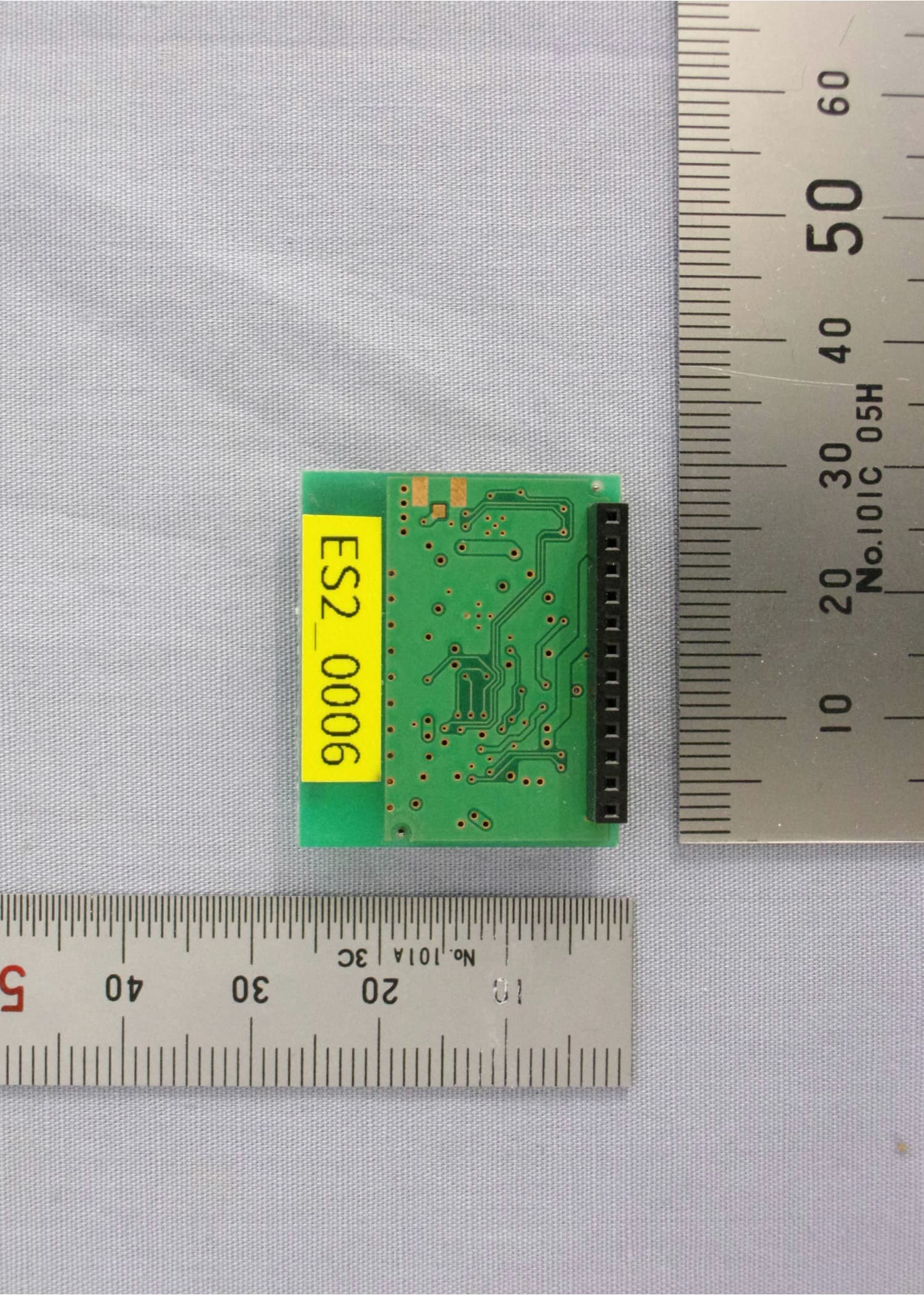
PocketWizard OEM Radio Transmitter Module (T42) Mfg. by LPA Design for Sekonic Light Meters Theory of operation: The radio transmitter modules consist of a CPU chip, PLL, and VCO/AM Modulator. The CPU is a microcontroller with firmware that connects the radio module to the host CPU of the Sekonic Light meters. The two CPU’s (host & module) talk by way of logic level RS-232 commands. When the module CPU receives a command to change to a new channel, it loads the PLL with a new reference divider number from a channel look up table in it’s internal ROM. The module has the ability to switch between 32 different “channels”. See the frequency table for details. When the module gets a trigger command or a trigger pulse on the trigger input pin, it powers up the PLL and VCO parts on the board. It loads the PLL with the divider number, waits for a PLL lock detection, then keys on the RF amplifier and does a “fine” adjustment to the PLL. When the amplifier is turned on, the VCO in the PLL can shift off frequency by as much as 50KHz. By letting the PLL adjust for one milisecond before starting the actual command data pulses, the frequency error drops to less than 10KHz maximum at the start of the RF command. Once the PLL has been locked and the “fine tune” adjustment has completed, the modules CPU keys ON and OFF (OOK) the RF amplifier to AM modulate the carrier. The command packet is shifted out at 15uS bit rate for either 16 or 24 bits depending on the channel. Channels 17-32 are 24 bit, channels 1-16 are 16 bit. Each command transmission is sent three times with a blanking period of 3ms between each copy. The 1ms “fine tune” PLL adjustment is only done once at the very beginning of a “full burst”. The PLL, RF amplifier and CPU are then put into a low power shut down mode until the next trigger. Frequency Table: ChannelFrequencyComments 1-16344.04MHzAll on same frequency, but different codes sent (16 bits) 17346.5MHz24 bits sent (Compatible with LPA Design PocketWizard MAX) 18347.0MHz“ 19347.5MHz“ 20348.0MHz“ 21348.5MHz“ 22349.0MHz“ 23349.5MHz“ 24350.0MHz“ 25350.5MHz“ 26351.0MHz“ 27351.5MHz“ 28352.0MHz“ 29352.5MHz“ 30353.0MHz“ 31353.5MHz“ 32354.0MHz“
Test Report
February 15, 2001 Elite Electronic Engineering, Inc. 1516 Center Circle Downers Grove, IL 60515 Attn:Mr. Richard King Dear Richard: Enclosed you will find the revised report of measurements for the Sekonic Wireless Light Meter, Model L-608/L-608CINE, Serial No. n/a, FCC ID: PFK-608-01. I trust that you will find the enclosed to be complete; however, should you have any questions or require any additional information, please feel free to contact us. Very truly yours, RETLIF TESTING LABORATORIES Scott Wentworth Manager Enc. (as stated) Customer: Test Sample: Model No: Test Method: Notes: Date: 1/4/2001 Tech: T. Firkowski Sheet 1of3 Report No. R-3720N2 Retlif Testing Laboratories Sekonic Corporation Wireless Light Meter L-608 Duty Cycle Plots CH16 344 MHz Test Report No. R-3720N2 FCC ID: PFK-608-01 APPLICANT MANUFACTURER Sekonic Corporation 7-24-12, Oizum-Gakeun-Cho Nerima-Ku, Tokyo 178-8686 JAPAN SAME TEST SPECIFICATION: FCC Rules and Regulations Part 15, Subpart C, Para. 15.231 TEST PROCEDURE: ANSI C63.4:1992 TEST SAMPLE DESCRIPTION BRANDNAME: Sekonic MODEL: L-608/L-608CINE TYPE: Wireless Light Meter POWER REQUIREMENTS: 3VDC Internal Battery FREQUENCY BAND OF OPERATION: 344MHz to 354MHz (32 Discrete Channels) MODULATION: Pulsed (On/Off Keying) TYPE OF TRANSMISSION: Control Signal (Pulse Recognition Codes) FREQUENCIES TESTED: 344.04MHz, 348.97MHz and 353.97MHz FCC ID: PFK-608-01 APPLICABLE RULE SECTION: Part 15, Subpart C, Section 15.231 TESTS PERFORMED Spurious Emissions Field Strength of Fundamental Occupied Bandwidth, 0.25% of Fundamental Frequency Duty Cycle Determination TEST SAMPLE OPERATION The EUT is battery operated and was tested with new batteries installed. The device is normally manually operated and transmits a 3 packet burst control signal. Normal operation of the EUT complies with the parameters required in Part 15, Subpart C, Section 15.231. For testing purposes only the EUT was configured to continuously transmit. The Sekonic models L-608 and L-608CINE are electronically identical and utilize the exact same RF module. The only difference between these two models is the type of information which can be displayed on the LCD screen when the light meters are being used for cinematography measurements. Test Report No. R-3720N2 FCC ID: PFK-608-01 The L-608CINE model is capable of displaying more CINE speeds. TEST SAMPLE / TEST PROGRAM CThe transmitter is manually activated. CThe transmitter does not perform periodic transmissions at regularly predetermined intervals. CThe device can not be employed for RC purposes involving security. CThe fundamental field strength at 344.04MHz did not exceed 7250.01FV/M (Average) at a test distance of 3 meters. The fundamental field strength at 348.97MHz did not exceed 7457.08FV/M (Average) at a test distance of 3 meters. The fundamental field strength at 353.97MHz did not exceed 7665.54FV/M (Average) at a test distance of 3 meters. CThe field strength of harmonic and spurious emissions did not exceed 725.0FV/M or 500FV/M as applicable at 344.04MHz. The field strength of harmonic and spurious emissions did not exceed 745.71FV/M or 500FV/M as applicable at 348.97. The field strength of harmonic and spurious emissions did not exceed 766.54FV/M or 500FV/M as applicable at 353.97. CThe device can operate at 32 discrete frequencies over the range of 344 to 354MHz. The device was tested at the frequencies of 344.04MHz, 348.97MHz and 353.97MHz. The bandwidth of emissions did not exceed 0.25% of the operating frequency and was determined as follows: Fundamental Frequency=344.04MHz 0.25% of Center Frequency=0.86MHz 0.86 divided by 2=0.43MHz Bandwidth Range=Fundamental Frequency + and - 0.43MHz 344MHz - 0.43MHz=343.61MHz 344MHz + 0.43MHz=344.47MHz Bandwidth Range=343.61MHz - 344.47MHz Fundamental Frequency=348.971MHz 0.25% of Center Frequency=0.872MHz 0.872 divided by 2=0.436MHz Bandwidth Range=Fundamental Frequency + and - 0.436MHz 348.97MHz - 0.436MHz=348.534MHz Test Report No. R-3720N2 FCC ID: PFK-608-01 348.97MHz + 0.436MHz=349.406MHz Bandwidth Range=348.53MHz - 349.41MHz TEST SAMPLE / TEST PROGRAM (continued) Bandwidth Calculations continued: Fundamental Frequency=353.971MHz 0.25% of Center Frequency=0.884MHz 0.884 divided by 2=0.442MHz Bandwidth Range=Fundamental Frequency + and - 0.436MHz 353.97MHz - 0.442MHz=353.528MHz 353.97MHz + 0.442MHz=354.412MHz Bandwidth Range=353.53MHz - 354.41MHz CThe device uses an internal antenna. CRadiated Emissions from the EUT were measured in all three axis. Worst case emissions were found with the EUT in the vertical upright position. This orientation is also the position in which the device will normally be used. The attached Radiated Emissions test data is representative of this worst case orientation. DETERMINATION OF FIELD STRENGTH LIMITS The field strength limits shown below were calculated as instructed in Section 15.231. Fundamental Frequency: 344.04MHz Where F is the frequency in MHz, the formula for calculating the maximum permitted fundamental field strength for the band 260-470MHz, FV/m at 3 meters is as follows: 41.6667(F) - 7083.3333 =Field Strength Limit (FV/m) 41.6667 x 344.04=14335.01147 14335.01147 - 7083.3333=7251.678168 Field Strength Limit=7251.68 FV/m The maximum permitted unwanted emission level is 20dB below the maximum permitted fundamental level. Test Report No. R-3720N2 FCC ID: PFK-608-01 TEST SAMPLE / TEST PROGRAM (continued) Field Strength Limit Calculations continued: Fundamental Frequency: 348.97MHz Where F is the frequency in MHz, the formula for calculating the maximum permitted fundamental field strength for the band 260-470MHz, FV/m at 3 meters is as follows: 41.6667(F) - 7083.3333 =Field Strength Limit (FV/m) 41.6667 x 348.97=14540.4283 14540.4283 - 7083.3333=7457.094999 Field Strength Limit=7457.09 FV/m The maximum permitted unwanted emission level is 20dB below the maximum permitted fundamental level. Fundamental Frequency: 353.97MHz Where F is the frequency in MHz, the formul…
Text truncated - open the document above for the full version.
Contact Information
Applicant
Hiroshi Harada(Director)
Technical Contact
Retlif Testing LaboratoriesJohn Monahan
[email protected](603) 497-4600
101 New Boston Road · Goffstown, New Hampshire · United States
Non-Technical Contact
Retlif Testing LaboratoriesScott Wentworth
[email protected](603) 497-4600
Test Firm
Retlif Testing LaboratoriesScott Wentworth
Technical Specifications
| # | Rule Parts | Frequency Range | Power Output |
|---|---|---|---|
| 1 | 15.231 | 344 MHz - 354 MHz | - |
Other Applications from Sekonic Corporation
PFK-TXMPR
Aug 04, 2026Radio TX Module.
Equipment Class
DXX - Part 15 Low Power Communication Device Transmitter
PFK-478-01
Aug 12, 2012Light Meter
Equipment Class
DSC - Part 15 Security/Remote Control Transmitter
PFK-RT32-03
Feb 28, 2012Remote Flash Control Transceiver
Equipment Class
DSR - Part 15 Remote Control/Security Device Transceiver
PFK-500-01
Jan 07, 2008Color Meter with Wireless Flash Control Transcieve
Equipment Class
DSR - Part 15 Remote Control/Security Device Transceiver
PFK-RT32-01
Sep 05, 2006Falsh Control Radio Module
Equipment Class
DSC - Part 15 Security/Remote Control Transmitter